Báo cáo hóa học: " Research Article Improving the Quality of Color Colonoscopy Videos" pot
Bạn đang xem bản rút gọn của tài liệu. Xem và tải ngay bản đầy đủ của tài liệu tại đây (7 MB, 7 trang )
Hindawi Publishing Corporation
EURASIP Journal on Image and Video Processing
Volume 2008, Article ID 139429, 7 pages
doi:10.1155/2008/139429
Research Article
Improving the Quality of Color Colonoscopy Videos
Rozenn Dahyot, Fernando Vilari
˜
no, and Gerard Lacey
Department of Computer Science, School of Computer Sc ience and Statistics, Trinity College Dublin,
College Green, Dublin 2, Ireland
Correspondence should be addressed to Rozenn Dahyot,
Received 1 August 2007; Revised 20 November 2007; Accepted 22 January 2008
Recommended by Shoji Tominaga
Colonoscopy is currently one of the best methods to detect colorectal cancer. Nowadays, one of the widely used colonoscopes has a
monochrome chipset recording successively at 60 Hz R, G,andB components merged into one color video stream. Misalignments
of the channels occur each time the camera moves, and this artefact impedes both online visual inspection by doctors and offline
computer analysis of the image data. We propose to restore this artefact by first equalizing the color channels and then performing
a robust camera motion estimation and compensation.
Copyright © 2008 Rozenn Dahyot et al. This is an open access article distributed under the Creative Commons Attribution
License, which permits unrestricted use, distribution, and reproduction in any medium, provided the original work is properly
cited.
1. INTRODUCTION
Colorectal cancer is the second leading cause of cancer death
in the United States and colonoscopy, by removing polyps
early, is currently one of the best methods to reduce this fatal-
ity [1]. Colonoscopy is a minimally invasive endoscopic ex-
amination of the colon and the distal part of the small bowel
with a fiber optic camera on a flexible tube. The video is in-
spected in realtime by the doctors to give a visual diagnosis
(e.g., ulceration, polyps). This procedure also gives the op-
portunity for biopsy of suspected lesions.
The quality of endoscopic screening is of significant con-
cern in the medical community. Large interendoscopist vari-
ation in the number of polyps being missed has been mea-
sured in clinical studies [1]. Although no definitive cause for
the high miss rates has been identified, the speed of cam-
era movement has been suggested as a cause. Our research
is within this context of identifying image quality artefacts
that may be contributory factors to the high incidence of miss
rates in endoscopy.
The inspection of colonoscopy videos can also be done
offline, and computer aided methods are currently developed
to assist medical doctors. For instance, in [2], a method is
proposed to detect tumors in colonoscopy videos using color
wavelet covariance and linear discriminant analysis. In [3],
the video is used to assess the endoscopist’s skills by esti-
mating the camera motion. In [4], edge detection and region
growing are used to help the control of the colonoscope. In
[5], an automatic labeling system for colonoscopy videos is
presented using eye tracking of experts for training and in-
dexing purposes. Labeled data is then used to feed a support
vector machine classifier to automatically detect tumors.
Endoscopes used in hospital use different imaging sys-
tems. Indeed, some endoscopic systems use color chipset
cameras. However, more recent endoscopes use mono-
chrome chipsets with successive color filters in order to im-
prove spatiotemporal resolution of the videos. Those are now
more commonly used in hospitals [6]. However, one ma-
jor problem occurs with monochrome chipset cameras: the
three color bands R, G,andB composing each image are
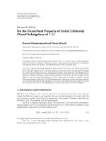
sometimes temporally desynchronized. This problem is il-
lustrated by the image in Figure 1.Thecurrentprocedure
used by doctors when they detect a potentially infected area
of the colon is to keep the camera steady the best they can
while they visually inspect the images. Moreover, this recur-
rent misalignment of color channels in colonoscopy videos
can impede any software using color image processing tech-
niques to assist doctors in their diagnosis.
In this article, we propose in Section 2 to model the
recording process of images by monochrome chipset endo-
scopes using successive color filters. Following this model-
ing, a short review of related problems is given in Section 3.
2 EURASIP Journal on Image and Video Processing
Figure 1: The image I
51
has misaligned color channels.
In Section 4, we present one possible solution to remove
the color misalignment and this is validated with experi-
mental results in Section 5. Finally, a conclusion is drawn
in Section 6. Potential benefits of this work include facili-
tating the human and computer-aided visual inspection of
colonoscopy videos performed online and offline.
2. COLONOSCOPY VIDEOS
The use of electronic imaging for endoscopy has been around
for a long time [7]. The recordings from more recent cameras
have better spatiotemporal resolution and work in a similar
way as described in [7]: a monochrome image is produced
by a black and white chip and is filtered by pulsed light to
an RGB colored system. This setting explains the artefact ap-
pearing in the recordings as illustrated in Figure 1.Because
the color channels of each image are not recorded at the same
time and because the camera is most of the time moving, the
RGB components of the images are misaligned in the videos.
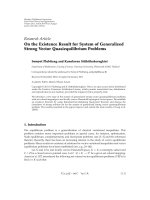
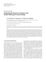
Figure 2 illustrates the problem: the black oriented curve
symbolized the camera trajectory. As the camera moves (at
changing speed) on this trajectory, the bands R
t−δ
R
, G
t
,and
B
t+δ
B
are recorded at different times and are grouped to form
the image I
t
in the video. The index t actually corresponds to
the frame number of the color frame I
t
in the color video, and
also indexes the corresponding band G. The variables δ
R
and
δ
B
used with t to index R and B emphasize the fact that those
are not recorded at the exact same time as G
t
. Due to the
camera motion in between those recording times, the RGB
bands in I
t
are misaligned.
Monochrome chip endoscopes give, however, a better
spatial resolution as a 3-chip camera or a bayer filter, and
introduce approximations to the spatial/color resolution.
Also, the LED lighting system can only produce white light
through a combination of red, green, and blue LEDs (there
are no “white” LEDs). Thus, sequential RGB delivers the best
“static” image quality, which is important clinically.
Colonoscopy videos are recorded in a specific environ-
ment where several damaging events can occur and blur the
images. As spotted in [3], out-of-focus frames usually origi-
nate from a too-close focus into the colon, or because of sub-
stances (e.g., air bubbles) covering the camera lens. Hwang
R
t−δR
G
t
B
t+δB
R
t+1−δR
G
t+1
B
t+1+δB
Figure 2: Modeling the problem: R, G,andB components of the
images are recorded at different times and the camera moves at dif-
ferent positions.
et al. [3] propose to filter out those noninformative frames
before performing any analysis. Using Fourier transform,
they first classify noninformative frames (blurred) from in-
formative ones.
Other artefacts occur in colonoscopy videos such as miss-
ing data. Indeed, the nature of the colon and its humidity
explain the occurrences of specular effects on its surface: the
light projected from the colonoscope is entirely reflected in
some areas of the colon surface. This creates saturated values
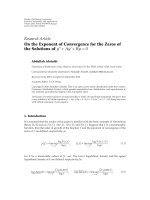
(equal to 255) in the color channels of the images. Figure 1
presents some specular regions (white spots). Figure 3(top)
shows the color channels separately and the specular regions
appear in each of them as white spots. Note that the position
of those regions depends on the position and the direction of
the light on the camera. Since the three color channels have
not been recorded at the same time and therefore are likely to
not have been recorded at the same positions, those specular
regions do not always appear as white (but also as reddish or
greenish) in the original and restored frames (see Figures 1
and 5). In those specular regions, some of the color informa-
tion has been lost.
3. RELATED WORKS
The misalignment of color channels in images recorded by
endoscopes has only been tackled by Badiqu
´
e et al. [8]. Tak-
ing the green channel as the reference frame, they proposed
to match the red and the blue channels to it. Phase correla-
tion is used to estimate locally the motion shift in between
R and G,andB and G. The local shift map is then used to
compensate the R and B to match G.
In [9], chromatic aberrations of lenses that provoke the
color channels to be misaligned are corrected. This aber-
ration is compensated by first calibrating the camera on a
chessboard for each color channel and then the displacement
is estimated and compensated. The displacement in between
RGB is the same for any image recorded by the same camera,
so the calibration has to be performed once. The green chan-
nel is also chosen as the reference color as it is midway within
the visible spectrum [9]. Calibration cannot be used in our
context since our misalignment is due to the motion of the
camera that is changing and unpredictable.
In [10], multiplex fluorescence in situ hybridation (M-
FISH), an imaging system to analyze chromosomes, shows
misregistrations in between the 6 channels recorded by the
Rozenn Dahyot et al. 3
microscope which hampers the classification. The misalign-
ment is generated from a combination of sources: lens dis-
tortion with respect to wavelength, and mechanical mis-
alignment (e.g., vibrations) during the registration. An affine
transformation is estimated using mutual information that is
computationally expensive to optimize [11].
Motion estimation techniques can be classified into two
categories [12]: frequency domain methods and spatial do-
main methods. The phase correlation method used in [8]be-
longs to the first category. It is not robust and limited by the
displacement it can model. In the second category of meth-
ods, we propose to use the motion estimation proposed in
[13] that has real-time potentials and is robust to outliers
(e.g., specular areas).
4. A NEW RESTORING SCHEME
4.1. Overview
Considering an original frame I
t
from a colonoscopy video,
it is composed by the three color channels I
t
= (R
t−δR
,
G
t
, B
t+δB
) recorded at three different times. No prior hy-
potheses are assumed about the delays δR and δB (they can
be different and negative). Our framework is therefore quite
general and does not depend on the specification of the
recording hardware used.
Our restoration method can be described in the follow-
ing three steps.
(1) Color channels equalization. This first process trans-
forms R
t−δR
and B
t+δB
into R
t−δR
and B
t+δB
,respec-
tively, by histogram equalization with G
t
. This process
is detailed in Section 4.2.
(2) Camera motion estimation. Considering the equalized
frame
I
t
= (R
t−δR
, G
t
, B
t+δB
), the six camera motion
parameters, noted by Θ
R
t
and Θ
B
t
,areestimatedin
between (
R
t−δR
, G
t
)and(B
t+δB
, G
t
), respectively.
Section 4.3 presents the robust estimation scheme.
(3) Motion compensation. The original image I
t
= (R
t−δR
,
G
t
, B
t+δB
) is compensated and the restored image is
noted by I
c
t
= (R
c
t
−δR
, G
t
, B
c
t+δB
). R
t−δR
and B
t+δB
are
compensated to align G
t
using motion parameters Θ
R
t
and Θ
B
t
,respectively.
4.2. Color channels equalization
One major difficulty of our problem is to put in correspon-
dence the R channel (resp., the B channel) with the G one.
The gray-level content of each channel is different. We need
to define a transformation so that the R values (resp., the
B values) can be matched with the green ones. A similar
problem arises when restoring flicker in videos. Flicker cor-
responds to random variations of brightness in the videos
and several modelings have been proposed [14]. In partic-
ular, one modeling allows to simply compute the nonlinear
transformation from one cumulative histogram of gray lev-
els to another. It is one of the simplest and earliest method to
equalize the gray-level dynamics of two images [15].
Considering the cumulative histograms C
R
, C
G
,andC
B
of each of the color channels (R
t−δR
, G
t
, B
t+δB
), the transfer
R
51−δR
(a)
G
51
(b)
B
51+δB
(c)
R
51−δR
(d)
G
51
(e)
B
51+δB
(f)
Figure 3: Original color channels of I
51
and their equalized compo-
nents
R
51−δR
and B
51+δB
.
functions f
R
(resp., f
B
) to transform the gray-level values of
R
t−δR
to match those of G
t
(resp., to transform the gray-level
values of B
t+δB
to match those of G
t
)arecomputedby[15]
f
R
(v) = C
−1
G
◦C
R
(v),
f
B
(v) = C
−1
G
◦C
B
(v).
(1)
f
R
(resp., f
B
) is applied to each value of R
t−δR
(resp.,
B
t+δB
). The result of those transformations is shown in
Figure 3(bottom). Gray-level values in
R
51−δR
and B
51+δB
are
more similar to those in G
51
.
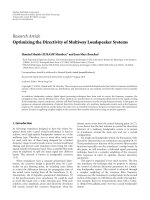
The effect of this equalization can also be assessed by
computing the histograms of the differences ε
= B
t+δB
−
G
t
, ε = B
t+δB
− G
t
, ε = R
t−δR
− G
t
and ε = R
t−δR
− G
t
.
Figure 4 presents those histograms for the frame I
51
.Wecan
notice that those histograms of differences after equalization
are centered on zero. This is a requirement to apply the mo-
tion estimation as explained in the next section.
4.3. Camera motion estimation
We use a 6-p ara mete r affine camera motion instead of 2 used
by [8], as it is better suited to the zooming effect created in
colonoscopy videos when the camera is moving backward
and forward. The frame rate of the endoscope used is 60
fps meaning that in between the recording of the R compo-
nent and the successive G, only 0.0167 s has passed. The 6-
parameter motion model is then expected to be sufficient. It
is a good tradeoff between complexity and representativeness
[13].
We only present here the estimation of the displacement
in between R
t−δR
and G
t
. It is the same process for matching
B
t+δB
to G
t
. In the following, we simplify the notation replac-
ing Θ
R
t
by Θ.
4 EURASIP Journal on Image and Video Processing
3002001000−100−200−300
0
200
400
600
800
1000
1200
1400
1600
1800
2000
(a)
3002001000−100−200−300
0
500
1000
1500
2000
2500
(b)
Figure 4: (a) Histograms of the differences ε = B
51+δB
− G
51
(blue continuous) and ε = B
51+δB
− G
51
(black dots). (b) Histograms of the
differences ε
= R
51−δR
−G
51
(red continuous) and ε = R
51−δR
−G
51
(black dots).
The displacement to apply to a pixel at position x = (x, y)
in the image R
t−δR
to match G
t
is expressed by
F(x, Θ)
=
a
1
a
2
a
3
a
4
x
y
+
d
x
d
y
,(2)
where the camera motion parameter to estimate is Θ
=
(a
1
, a
2
, a
3
, a
4
, d
x
, d
y
). Following [13], Θ is estimated by max-
imizing a probability of the form
Θ = arg max
Θ
P (ε) ∝ exp
−
1
2
x
ρ
ε(x,Θ)
σ
ρ
,(3)
where ε(x, Θ)
G
t
(x) − R
t−δR
(F(x, Θ)), ρ is a robust func-
tion, and σ
ρ
is its scale parameter that controls the rejection
of outliers in the estimation. More details on the estimation
process can be found in [13]. A robust procedure is preferred
not to be sensitive to outliers that arise when the content in
the two images to match has changed, or when artefacts oc-
cur (e.g., specular areas).
The function ρ is basically reproducing the behavior of a
centered Gaussian distribution when the difference ε(x, Θ)is
inferior to σ
ρ
. On the contrary, when the difference ε(x, Θ)
is much larger than σ
ρ
, the term is penalized so that its con-
tribution in the estimation is decreased. We have chosen a
monotone robust function [16]
ρ(ε)
= 2
1+ε
2
−2. (4)
This allows to not penalize too strongly pixels that are not
perfectly matched after the equalization process. Similarly as
in [13], the scale parameter is automatically computed and is
proportional to the median absolute deviation (MAD).
4.4. Restoring the color frame
Once the displacements Θ
R
t
and Θ
B
t
have been estimated, the
compensated frames R
c
t
−δR
and B
c
t+δB
are computed from the
original frames R
t−δR
and B
t+δB
, and then rearranged in the
restored color image I
c
t
= (R
c
t
−δR
, G
t
, B
c
t+δB
). Figure 5 shows
Figure 5: Restored frame I
c
51
of I
51
.
the result of the restoration for the image I
51
(cf. Figure 1).
Note that the misalignment in this case was quite impor-
tant, but is, however, properly restored. Missing data in R
c
t
−δR
and B
c
t+δB
may appear on the edge of the restored frame de-
pending on the motion compensation. This effect appears
in Figure 5 where the bottom and right areas appear green.
This is because the red component has been properly aligned
with the green but there is no knowledge on the red values
on those (bottom and right) areas from the original frame
R
t−δR
. Those missing values are filled with zeros. One way to
improve the visualization is to crop the restored frame. Al-
ternatively, we are currently investigating inpainting meth-
ods to resolve this. Results shown in this article do present
those missing data which allow to appreciate the important
displacements that sometimes arise in colonoscopy videos.
The result of the restoration process is therefore better ap-
preciated looking at the center of the images and in particular
near the strong edges of the lumen.
5. EXPERIMENTAL RESULTS
We have collected several hours of colonoscopy in DV
compressed format. The assessment shown here is done
Rozenn Dahyot et al. 5
(I
c
7
, I
7
)
(a)
(I
c
12
, I
12
)
(b)
(I
c
32
, I
32
)
(c)
(I
c
46
, I
46
)
(d)
(I
c
58
, I
58
)
(e)
(I
c
151
, I
151
)
(f)
(I
c
169
, I
169
)
(g)
(I
c
179
, I
179
)
(h)
Figure 6: Successful restorations: the left images are the restored frames and the right ones are the originals.
qualitatively by visual inspection on more than 200 im-
ages coming from different sequences. Some restored videos
can be seen at />DemosColonoscopy.html.
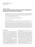
Examples of successful restorations are reported in
Figure 6. For the image I
12
, the red and green color chan-
nels are misaligned in the original image (right). The mis-
alignment is corrected in the restored image (left). Successful
restorations: the left images are the restored frames and the
right ones are the originals.
It is difficult to assess quantitatively the restoration as we
do not know what is the groundtruth in our videos. We de-
fine a failed restoration when the restored image I
c
t
is worse
than the original one. Figure 7 shows two examples: the com-
pensated image I
76
is not worse than the original and is not
counted as a failure, but image I
134
is. We assessed that about
10% of the restored frames are worse than the originals.
Most of those failed restorations are explained by the really
low quality of the original images. Those images are blurred
with low edge content, or present really weird color dynam-
ics (e.g., image I
134
in Figure 7). It is understood that most of
those frames would have been classified as noninformative in
the system presented by Hwang et al. [3].
In conjunction with blurredness, a possible additional
source of error comes from specular areas which create
strong edges on which most motion estimators (including
ours) rely heavily in some particular situation. As explained
earlier, those specular areas may not be aligned in the R, G,
and B frames since they appear at different locations due to
the different orientations and positions of the camera at the
time of their recordings. When no other edge information
appears in the image than the specular areas, for instance in
6 EURASIP Journal on Image and Video Processing
(I
c
76
, I
76
)
(a)
(I
c
134
, I
134
)
(b)
(I
c
20
, I
20
)
(c)
Figure 7: The restoration of the image I
76
does not improve the
original image. The restored images I
c
134
and I
c
20
are worse than the
originals and are counted as failed restorations.
blurred and uniform color images, it is then likely that our
robust estimation process will compensate for the local mo-
tion of those specular areas instead of the global motion of
the camera. Those specular areas can be detected by search-
ing for saturated pixels (e.g., which values are close to 255)
and can be weighted down in our robust estimation scheme.
At last, DV uses chroma subsampling that creates arte-
facts in the R, G,andB frames. It means that when decoding
the frame in DV, we cannot recover clean R, G,andB chan-
nels as recorded by the endoscope.
Our current and future efforts for improving the restora-
tion aim at the following.
(i) Improving the quality of the images by avoiding compres-
sion that creates artefacts. It would be difficult to try to
recover clean R, G,andB frames from the DV files us-
ing a software solution. Instead, our current work in-
vestigates the use of dedicated hardware to acquire un-
compressed high definition color frames in real-time.
It is expected that our method to realign color channels
will then achieve even better performances on cleaner
data.
(ii) Detecting and reducing the failed restoration. We as-
sessed that 10% of the frames are not properly restored
and can be even worse than the originals. This can be
corrected by one of the following approaches.
(a) Not restoring noninformative images (i.e., images
that are too blurry). The detection of such blurry
frames is performed by Hwang et al. [3].
(b) The second possible approach is to include prior
information on the possible motions in the colon-
oscopy videos. Some estimated parameters are not
coherent with respect to previous and future esti-
mated parameters. Kalman filtering encapsulat-
ing priors could be used. Also the displacement
of the endoscope manually controlled by medical
doctors, in the temporal window of 1/60 seconds,
is bounded in the motion parameter space. As
canbeseeninFigure 7, the failed restorations
(frames 134 and 20) involve unrealistic displace-
ment. Current works aim at including more prior
information to constrain better the restoration.
(iii) Filling missing data using inpaint ing methods. This can
be used to improve further the quality of the images by
both correcting the borders of the images after color
channel realignment and also filling in specular areas.
6. CONCLUSION
Wehavepresentedanewmethodtorestoreframesfrom
colonoscopy videos that present a misalignment in their
color channels. This artefact is due to a delay in between the
recordings of the different channels and the camera motion
inside the colon creates the misalignments. Experimental re-
sults show that our method works well and mainly fails when
the quality of the images is very low. It is believed that any
computer-aided analysis of colonoscopy videos would bene-
fit from this restoration performed at an early stage.
ACKNOWLEDGMENTS
This work has been partly funded by the Enterprise Ireland
Project PC-2006-038 Endoview and the European Network of
Excellence on Multimedia Understanding through Semantics,
Computation and Learning (MUSCLE) FP6-5077-52, avail-
able at .
REFERENCES
[1] J.C.vanRijn,J.B.Reitsma,J.Stoker,P.M.Bossuyt,S.J.van
Deventer, and E. Dekker, “Polyp miss rate determined by tan-
dem colonoscopy: a systematic review,” American Journal of
Gastroenterology, vol. 101, no. 2, pp. 343–350, 2006.
[2] S. A. Karkani, D. K. Iakovidis, D. E. Maroulis, D. A. Karras, and
M. Tzivras, “Computer-aided tumor detection in endoscopic
video using color wavelet features,” IEEE Transactions on Infor-
mation Technology in Biomedicine, vol. 7, no. 3, pp. 141–152,
2003.
[3] S. Hwang, J. Oh, J. Lee, et al., “Automatic measurement of
quality metrics for colonoscopy videos,” in Proceedings of
the 13th Annual ACM International Conference on Multime-
dia (MULTIMEDIA ’05), pp. 912–921, Singapore, November
2005.
Rozenn Dahyot et al. 7
[4] S. J. Phee, W. S. Ng, I. M. Chen, F. Seow-Choen, and B. L.
Davies, “Automation of colonoscopy. II. Visual-control as-
pects,” IEEE Engineering in Medicine and Biology Magazine,
vol. 17, no. 3, pp. 81–88, 1998.
[5] F. Vilari
˜
no, G. Lacey, J. Zhou, H. Mulcahy, and S. Patchett, “Au-
tomatic labeling of colonoscopy video for cancer detection,” in
Proceedings of the 3rd Iberian Conference on Pattern Recogni-
tion and Image Analysis (IbPRIA ’07),J.Mart,J M.Bened,A.
M. Mendona, and J. Serrat, Eds., vol. 4477 of Lecture Notes in
Computer Sc ience, pp. 290–297, Springer, Girona, Spain, June
2007.
[6] J. Simpson, “Manual of canine and feline gastroenterology,” in
Gastrointestinal Endoscopy, pp. 34–49, chapter 4, British Small
Animal Veterinary Association, Gloucester, UK, 2nd edition,
2005.
[7] G. Berci and M. Paz-Partlow, “Electronic imaging in en-
doscopy,” Surgical Endoscopy, vol. 2, no. 4, pp. 227–233, 1988.
[8] E. Badiqu
´
e, N. Ohyama, M. Yachida, T. Honda, and J. Tsuji-
uchi, “Compensation of motion related blur in ccd color en-
doscope image,” in Proceedings of IEEE International Confer-
ence on Acoustic, Speech, and Signal Processing (ICASSP ’86),
vol. 11, pp. 1785–1788, Tokyo, Japan, April 1986.
[9] J. Mallon and P. F. Whelan, “Calibration and removal of lateral
chromatic aberration in images,” Pattern Recognition Letters,
vol. 28, no. 1, pp. 125–135, 2007.
[10] Y P. Wang, “M-FISH image registration and classification,”
in Proceedings of the 2nd IEEE International Symposium on
Biomedical Imaging: Macro to Nano (ISBI ’04), vol. 1, pp. 57–
60, Arlington, Va, USA, April 2004.
[11] G. Wollny, “Analysis of changes in temporal series of medical
images,” Ph.D. thesis, University of Leipzig, Germany, 2003.
[12] P. Vandewalle, S. S
¨
usstrunk, and M. Vetterli, “A frequency do-
main approach to registration of aliased images with applica-
tion to super-resolution,” EURASIP Journal on Applied Signal
Processing, vol. 2006, Article ID 71459, 14 pages, 2006.
[13] J. M. Odobez and P. Bouthemy, “Robust multiresolution esti-
mation of parametric motion models,” Journal of Visual Com-
munication and Image Representation, vol. 6, no. 4, pp. 348–
365, 1995.
[14] F. Piti
´
e, R. Dahyot, F. Kelly, and A. Kokaram, “A new robust
technique for stabilizing brightness fluctuations in image se-
quences,” in Proceedings of the 2nd Statistical Methods for Video
Processing Workshop, in conjunction with the European Confer-
ence on Computer Vision, vol. 3247, Springer, Prague, Czech
Republic, May 2004.
[15] R. C. Gonzales and P. Wintz, Digital Image Processing,
Addison-Wesley, Boston, Mass, USA, 2nd edition, 1987.
[16] C. V. Stewart, “Bias in robust estimation caused by disconti-
nuities and multiple structures,” IEEE Transactions on Pattern
Analysis and Machine Intelligence, vol. 19, no. 8, pp. 818–833,
1997.