Báo cáo hóa học: "Research Article Duplex Schemes in Multiple Antenna Two-Hop Relaying" potx
Bạn đang xem bản rút gọn của tài liệu. Xem và tải ngay bản đầy đủ của tài liệu tại đây (868.04 KB, 14 trang )
Hindawi Publishing Corporation
EURASIP Journal on Advances in Signal Processing
Volume 2008, Article ID 128592, 14 pages
doi:10.1155/2008/128592
Research Article
Duplex Schemes in Multiple Antenna Two-Hop Relaying
Timo Unger and Anja Klein
Fachgebiet Kommunikationstechnik, Institut f
¨
ur Nachrichtentechnik, Technische Universit
¨
at
Darmstadt, Merkstrasse 25, 64283 Darmstadt, Germany
Correspondence should be addressed to Timo Unger,
Received 31 July 2007; Accepted 20 January 2008
Recommended by Thomas Kaiser
A novel scheme for two-hop relaying defined as space division duplex (SDD) relaying is proposed. In SDD relaying, multiple an-
tenna beamforming techniques are applied at the intermediate relay station (RS) in order to separate downlink and uplink signals
of a bi-directional two-hop communication between two nodes, namely, S1 and S2. For conventional amplify-and-forward two-
hop relaying, there appears a loss in spectral efficiency due to the fact that the RS cannot receive and transmit simultaneously on
the same channel resource. In SDD relaying, this loss in spectral efficiency is circumvented by giving up the strict separation of
downlink and uplink signals by either time division duplex or frequency division duplex. Two novel concepts for the derivation of
the linear beamforming filters at the RS are proposed; they can be designed either by a three-step or a one-step concept. In SDD
relaying, receive signals at S1 are interfered by transmit signals of S1, and receive signals at S2 are interfered by transmit signals of
S2. An efficient method in order to combat this kind of interference is proposed in this paper. Furthermore, it is shown how the
overall spectral efficiency of SDD relaying can be improved if the channels from S1 and S2 to the RS have different qualities.
Copyright © 2008 T. Unger and A. Klein. This is an open access article distributed under the Creative Commons Attribution
License, which permits unrestricted use, distribution, and reproduction in any medium, provided the original work is properly
cited.
1. INTRODUCTION
There exists much ongoing work in the promising research
field of two-hop relaying [1, 2]. This paper focuses on
bidirectional two-hop communication between two nodes,
namely, S1 and S2 via an intermediate relay station (RS). It
is assumed that the downlink trafficloadfromS1toS2via
the RS is the same as the uplink trafficloadfromS2toS1via
the RS. Due to the high dynamic range between the signal
powers of downlink and uplink signals, typical transceivers
at S1, S2, and the RS cannot receive and transmit simultane-
ously on the same channel resource. In single-hop communi-
cation, where S1 and S2 can communicate directly with each
other, this problem is typically solved by time division duplex
(TDD) or frequency division duplex (FDD) [3]. In TDD,
there exist two orthogonal time-slots, one for the downlink
and another for the uplink. In FDD, there exist two orthog-
onal frequency bands, one for the downlink and another for
the uplink.
Most two-hop relaying schemes also assume a strict sep-
aration of downlink and uplink signals by either TDD or
FDD. These schemes are defined as one-way relaying schemes
since downlink and uplink can be regarded independently.
In amplify-and-forward (AF) two-hop relaying [4], the RS
receives a signal from either S1 or S2 on a first hop, ampli-
fies this signal, and retransmits it to either S2 or S1 on a sec-
ond hop. Due to the fact that a half-duplex RS cannot re-
ceive and transmit simultaneously on the same channel re-
source, two orthogonal channel resources are required, one
for the first hop and another for the second hop. If downlink
and uplink signals are separated by either TDD or FDD, the
number of required channel resources is doubled compared
to a single-hop communication. Regarding the spectral effi-
ciency of two-hop relaying, this leads to a trade-off between
the improved receive signal quality due to the reduced over-
all pathloss between S1 and S2 and the increase in required
channel resources due to the two-hop approach. In litera-
ture, there exist many one-way relaying schemes which try
to overcome this conceptual drawback of two-hop relaying.
However, there also exist schemes which relax the strict sep-
aration of downlink and uplink by TDD or FDD which are
also promising and in the focus of this work.
1.1. Related work
One approach is to design two-hop relaying schemes which
improve the spectral efficiency by allowing a smart reuse of
2 EURASIP Journal on Advances in Signal Processing
channel resources among multiple one-way relaying connec-
tions [5–7].
In [5], multiple RSs are divided into two groups that
alternately receive and transmit signals, that is, while one
group is receiving signals from the source node, the other
group is transmitting signals to the destination node. Since
the source transmits all the time in this scheme, the number
of required channel resources is the same as in the single-
hop case. However, the performance can be significantly de-
graded by co-channel interference between the two groups
of RSs. In [6],onesourcenodecommunicateswithK differ-
ent destination nodes via K different RSs. Firstly, the source
node transmits consecutively to the K RSs using K time slots.
Secondly, all RSs transmit simultaneously to their assigned
destination nodes in the relay time slot K +1.Obviously,
this protocol does not require double the resources com-
pared to the single-hop network, but only (K +1)/K.How-
ever, the performance may be significantly degraded by co-
channel interference from the RSs at the destination nodes.
The problem of co-channel interference is also addressed in
[7], where the co-channel interference is kept low by a smart
selection of simultaneously transmitting RSs in the relay time
slot.
Two other schemes which consider only one source and
one destination node are proposed in [8]. For the first
scheme, the communication between source and destination
node is assisted by two RSs. In the first time slot, one RS re-
ceives from the source node and the other RS transmits to
the destination node. In the second time slot, the RSs switch
their roles. Since the source may transmit in every time slot,
the number of required channel resources is the same as in
the single-hop case. However, since the two RSs use the same
channel resources, there still exists co-channel interference.
Further work on this first scheme considering the direct link
between S1 and S2 is presented in [9].
Thesecondschemefrom[8] which is termed two-way
relaying is of particular interest for this work. It has been first
introducedin[10] and it has attracted many similar works.
In contrast to all previous schemes, two-way relaying is es-
pecially developed for bidirectional communication. For the
first time, it relaxes the constraint that downlink and uplink
signals are transmitted on orthogonal time slots and/or or-
thogonal frequency bands. Hence, it uses neither TDD nor
FDD. In two-way relaying, S1 and S2 transmit simultane-
ously on a first channel resource to an RS which receives a
superposition of both signals. In general, there are two dif-
ferent approaches of how to process the receive signal at the
RS. For the decode-and-forward (DF) approach, the receive
signal at the RS is decoded and the two separated signals
from S1 and S2 are jointly re-encoded before retransmission.
For the AF approach, the receive signal is only amplified at
the RS before retransmission. For both approaches, a second
channel resource is used for the retransmission, and S1 and
S2 may utilize their knowledge about the interference term
which is coming from their own transmitted signal in order
to detect the desired signal. In [11], the rate regions of DF
two-way relaying are investigated. This work gives the opti-
mal relative sizes of the first and second channel resources in
order to maximize the achievable rate of DF two-way relay-
ing. Two-way relaying is closely connected to network coding
[12]. Actually, in network coding data packets from differ-
ent sources in a multinode computer network are jointly en-
coded at intermediate network nodes, thus saving network
resources, that is, DF two-way relaying can be interpreted
as network coding in the original sense with the extension
of allowing wireless links. In [13], the interconnection be-
tween AF two-way relaying and network coding is also es-
tablished. Like in [14], it is assumed that for DF two-way
relaying three orthogonal channel resources are required.
The first two resources are required for the transmission
from S1 and S2 to the RS, respectively. This scheme guar-
antees that both signals can be decoded separately at the RS.
The third resource is required for the retransmission of the
jointly re-encoded signal from the RS. It is shown in [13] that
AF two-way relaying provides a higher throughput for low
noise levels at the RS than the considered DF two-way relay-
ing which requires three instead of two orthogonal channel
resources.
Another technique which promises to improve the spec-
tral efficiency of two-hop relaying is the application of mul-
tiple antennas leading to multiple-input multiple-output
(MIMO) relaying [15]. In [16–18], it is shown that the per-
formance of a single AF two-hop relaying connection can
be significantly improved if channel state information (CSI)
is exploited at a multiple antenna RS allowing single-user
beamforming at the RS. In [19], multiuser beamforming is
applied at multiple RSs in order to supply multiple destina-
tions with their desired signals, that is, multiple AF two-hop
relaying connections are separated spatially. However, [16–
19] only assume one-way relaying schemes for the multiple
antenna RSs. In [20], multiple antennas and CSI at the RS
are applied in the context of DF two-way relaying. It is as-
sumed that the signals from S1 and S2 are decoded at the RS,
and two different schemes for the spatial precoding at the RS
before the retransmission are proposed. For the first scheme,
both decoded signals are re-encoded separately and linearly
combined by applying a spatial precoding matrix coming
from the singular value decomposition of the channel. For
the second scheme, both decoded signals are combined by a
bitwise exclusive or (XOR) operation, and the spatial precod-
ing is applied to the new single bit stream. It is shown that the
second approach outperforms the first approach in terms of
achievable rate. Although the schemes in [20] apply multiple
antennas in two-way relaying for the first time, decoding and
re-encoding are still required at the RS.
1.2. Own contribution
In this paper, an AF two-way relaying scheme with multi-
ple antennas and linear signal processing at the RS with-
out decoding and re-encoding is proposed leading to a new
duplex scheme, defined as space division duplex (SDD). In
SDD relaying, downlink and uplink are transmitted on the
same channel resources in time and frequency but separated
in space. This scheme circumvents the increase in required
channel resources for two-hop relaying. Since the RS in the
two-way relay channel is a receiver as well as a transmitter,
linear receive and transmit beamforming can both be applied
T. Unger and A. Klein 3
at the RS if CSI is available at the RS. The resulting spatial fil-
ter matrix at the RS is termed transceive filter matrix. Two
novel concepts for the design of this transceive filter are pro-
posed. It can be designed either in three independent steps
or in one step. For both concepts, the linear transceive fil-
ters fulfilling the zero forcing (ZF) and the minimum mean
square error (MMSE) criteria are derived and compared re-
garding their bit error rate (BER) performance. In SDD re-
laying, receive signals at S1 are interfered by transmit sig-
nals of S1, and receive signals at S2 are interfered by trans-
mit signals of S2. This interference is defined as duplex in-
terference. Since duplex interference can be perfectly deter-
mined at the receivers S1 and S2, it can be subtracted leading
to a very simple and efficient method, namely, subtraction
of duplex interference (SDI) which is proposed in this pa-
per. Furthermore, it is shown how the spectral efficiency of
SDD relaying may be improved for the case of different chan-
nel qualities on the two channels from the RS to S1 and S2,
respectively.
Regarding its spectral efficiency, SDD relaying is com-
pared to other relaying schemes which require the same ef-
fort in terms of number of antennas, achieving CSI, and
applied signal processing. Assuming multiple antennas, CSI
availability at the RS, and linear signal processing, one could
also exploit spatial diversity [21] at the RS instead of ap-
plying beamforming in SDD relaying. For that purpose, a
one-way relaying scheme applying receive and transmit max-
imum ratio combining (MRC) [22, 23] at the RS is proposed
which is defined as MRC relaying. For MRC relaying, double
the resources are required as for SDD relaying since down-
link and uplink have to be transmitted separately by either
TDDorFDD.However,itprovidesdiversitygainwhichcan
compensate the increase in required channel resources by
allowing higher transmission rates. Furthermore, a relaying
scheme applying a combination of receive MRC and trans-
mit beamforming (BF) at the RS is proposed which is defined
as MRC-BF relaying. In MRC-BF relaying, spatial diversity is
exploited for the reception from S1 and S2 at the RS and the
number of required channel resources for the transmission
from the RS to S1 and S2 is reduced.
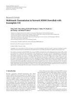
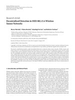
The channel resource requirements and the applied sig-
nal processing at the RS for SDD relaying, MRC relaying, and
MRC-BF relaying are summarized in Figure 1. In this paper,
the spectral efficiencies of all proposed relaying schemes are
investigated and compared to each other.
1.3. Notation
Throughout the paper, complex baseband transmission is
assumed. Let [
·]
T
,[·]
∗
,[·]
H
, ·
2
2
,(·)
−1
,det[·], diag[·],
and tr
{·} denote the transpose, the conjugate, the conjugate
transpose, the Euclidean norm, the inverse, the determinant
of the matrix argument, a diagonal matrix consisting of the
main diagonal elements of the matrix argument, and the sum
of the main diagonal elements of the matrix argument, re-
spectively. An identity matrix of size M and a null matrix of
size M
× M are denoted by I
M
and ∅
M
,respectively.E{·},
Re
{·}, and log
2
(·) denote the expectation, the real part, and
the logarithm to the basis two, respectively.
MRC-BF relaying MRC relayingSDD relaying
4 resources3 resources2 resources
S1 RS S2
Rx MRC
Tx MRC
Rx MRC
Tx MRC
Rx MRC
Rx MRC
Tx BF
Rx BF
Tx BF
??
Figure 1: Channel resource requirements of different relaying
schemes with applied signal processing at the RS: receive MRC (Rx
MRC), transmit MRC (Tx MRC), receive beamforming (Rx BF),
and transmit beamforming (Tx BF).
1.4. Outline
The system model of SDD relaying is given in Section 2.
Section 3 introduces the ZF and MMSE transceive filters
which are firstly given for a three-step design concept, and
secondly they are derived by a one-step design concept. In
Section 4, the duplex interference in SDD relaying is con-
sidered. Section 5 shortly introduces MRC and MRC-BF re-
laying. The required amount of CSI for the different relay-
ing schemes and extensions of these schemes are discussed
in Section 6.InSection 7, the sum rate for SDD relaying
is given. Simulation results regarding the BER performance
and the spectral efficiency of SDD relaying are presented in
Section 8. Section 9 concludes this work.
2. SYSTEM MODEL SDD RELAYING
In the following, the communication between two nodes,
namely, S1 and S2, which exchange information via an in-
termediate RS, is considered. The nodes cannot exchange
information directly, for example, due to shadowing condi-
tions. Due to the half-duplex constraint, all stations cannot
transmit and receive simultaneously on the same channel re-
source. S1 and S2 are equipped with M
(1)
and M
(2)
antennas,
4 EURASIP Journal on Advances in Signal Processing
respectively. For SDD relaying, it is required that S1 and S2
are equipped with the same number of antennas, that is,
M
(1)
= M
(2)
= M,(1)
and the RS has to be equipped with
M
(RS)
≥ M
(1)
+ M
(2)
= 2M,(2)
antennas in order to be able to separate down and uplink
signals by spatial beamforming.
The data vector x
(1)
=
x
(1)
1
, , x
(1)
M
T
of data symbols
x
(1)
n
, n = 1, , M willbetransmittedfromS1toS2,and
the data vector x
(2)
=
x
(2)
1
, , x
(2)
M
T
of data symbols x
(2)
n
,
n
= 1, , M will be transmitted from S2 to S1. The corre-
sponding transmit covariance matrices are given by R
x
(k)
=
E
x
(k)
x
(k)
H
, k = 1, 2. The overall data vector is defined as
x
=
x
(1)
T
, x
(2)
T
T
with covariance matrix R
x
= E{xx
H
}.For
simplicity, the wireless channel is assumed to be flat fading
so that all following considerations are applicable, for exam-
ple, to multicarrier systems. Hence, the channel between Sk,
k
= 1, 2, and the RS may be described by the channel matrix,
H
(k)
R
=
⎡
⎢
⎢
⎢
⎢
⎢
⎣
h
(k)
1,1
··· h
(k)
1,M
.
.
.
.
.
.
.
.
.
h
(k)
M
(RS)
,1
··· h
(k)
M
(RS)
,M
⎤
⎥
⎥
⎥
⎥
⎥
⎦
,(3)
where h
(k)
m,n
, m = 1, ,M
(RS)
,andn = 1, , M are complex
fading coefficients. The overall channel matrix for the trans-
mission from S1 and S2 to the RS is defined as
H
R
=
H
(1)
R
H
(2)
R
. (4)
The channel between the RS and Sk, k
= 1,2 is described by
the channel matrix,
H
(k)
T
=
⎡
⎢
⎢
⎢
⎢
⎢
⎣
h
(k)
1,1
···
h
(k)
1,M
(RS)
.
.
.
.
.
.
.
.
.
h
(k)
M,1
···
h
(k)
M,M
(RS)
⎤
⎥
⎥
⎥
⎥
⎥
⎦
,(5)
where
h
(k)
n,m
, n = 1, ,M,andm = 1, , M
(RS)
are complex
fading coefficients. Assuming channel reciprocity, channel
matrix H
(k)
T
is the transpose of H
(k)
R
, that is, H
(k)
T
= H
(k)
T
R
if
the channel is constant during one transmission cycle which
includes the transmission from S1 to S2 and the transmission
from S2 to S1. For the following considerations, the more
generalcaseofH
(k)
T
/
= H
(k)
T
R
is regarded. The overall chan-
nel matrix for the transmission from the RS to S2 and S1 is
defined as
H
T
=
⎡
⎣
H
(2)
T
H
(1)
T
⎤
⎦
. (6)
In SDD relaying, the data vectors x
(1)
and x
(2)
are ex-
changed between S1 and S2 during two orthogonal time
slots. During the first time slot, S1 and S2 transmit simul-
taneously to the RS. Since spatial filtering will only be ap-
plied at the RS, only scalar transmit filters Q
(1)
= q
(1)
I
M
and
Q
(2)
= q
(2)
I
M
are applied at S1 and S2. These transmit filters
are required in order to fulfill the transmit energy constraints
at S1 and S2. Assuming that E
(1)
and E
(2)
are the transmit en-
ergies of nodes S1 and S2, the transmit energy constraints are
given by
E
q
(k)
x
(k)
2
2
=
E
(k)
, k = 1, 2. (7)
Assuming positive and real scalar transmit filters, the trans-
mit energy constraints from (7)leadto
q
(k)
=
E
(k)
tr{R
x
(k)
}
k = 1, 2, (8)
that is, the transmit energy of each node is equally shared
among all transmit antennas of the node. The overall trans-
mit filter is given by the block diagonal matrix,
Q
=
⎡
⎣
Q
(1)
0
M
0
M
Q
(2)
⎤
⎦
. (9)
The receive vector y
RS
at the RS is given by
y
RS
= H
R
Qx + n
RS
, (10)
where n
RS
is an additive white Gaussian noise vector with
covariance matrix R
n
RS
= E{n
RS
n
H
RS
}.Thecovariancematrix
of the RS receive vector y
RS
results in
R
y
RS
= E
y
RS
y
H
RS
= H
R
QR
x
Q
H
H
H
R
+ R
n
RS
. (11)
At the RS, a linear transceive filter G is designed in order to
ensure that S1 receives an estimate of data vector x
(2)
and S2
receives an estimate of data vector x
(1)
. There are several pos-
sibilities of how G can be designed which will be discussed in
Section 3. After applying transceive filter G, the RS transmit
vector is given by
x
RS
= Gy
RS
= G
H
R
Qx + n
RS
. (12)
TheRStransmitvectorx
RS
has to fulfill the transmit energy
constraint at the RS, that is,
E
x
RS
2
2
≤
E
(RS)
, (13)
where E
(RS)
is the maximum transmit energy at the RS. In
the following, the estimate for data vector x
(1)
at S2 is termed
x
(1)
,andtheestimatefordatavectorx
(2)
at S1 is termed
x
(2)
. For each receiving node, the scalar receive filters P
(1)
=
p
(1)
I
M
at S2 and P
(2)
= p
(2)
I
M
at S1 with filter coefficients
p
(1)
and p
(2)
are assumed. The overall receive filter matrix
results in
P
=
⎡
⎣
P
(1)
0
M
0
M
P
(2)
⎤
⎦
. (14)
T. Unger and A. Klein 5
The overall estimated data vector x = [x
(1)
T
, x
(2)
T
]
T
is given
by
x = P
H
T
GH
R
Qx + H
T
Gn
RS
+ n
R
, (15)
where n
R
=
n
(2)
T
R
n
(1)
T
R
T
is the combined additive white
Gaussian noise vector of S2 and S1 with n
(2)
R
and n
(1)
R
being
the noise vector at S2 and S1, respectively. The covariance
matrix of n
R
is defined by R
n
R
= E
n
R
n
H
R
.
3. LINEAR TRANSCEIVE FILTERS FOR SDD RELAYING
In the following, it is assumed that instantaneous CSI about
H
R
and H
T
is available at the RS. In this case, there are two
concepts of how the transceive filter G at the RS can be de-
signed. For the first concept, G is assumed as a combination
of a linear receive filter G
R
, a weight matrix G
Π
, and a lin-
ear transmit filter G
T
where all filters can be determined in-
dependently, that is, the transceive filter is designed in three
steps. For the second concept, G is designed in one step with-
out separating it into a receive, a weight, and a transmit filter
part.
3.1. Three-step design for the linear transceive filter
In the first step, the RS receive vector y
RS
is multiplied with
the linear receive filter matrix G
R
resulting in the RS estima-
tion vector,
x
RS
=
x
(1)
T
RS
, x
(2)
T
RS
T
= G
R
y
RS
(16)
with the estimate
x
(1)
RS
for x
(1)
and the estimate x
(2)
RS
for x
(2)
,
respectively.
In the second step,
x
RS
is multiplied with the RS weight
matrix
G
Π
=
⎡
⎢
⎢
⎢
⎢
⎢
⎢
⎣
β
M
I
M
0
M
0
M
(1 − β)
M
I
M
⎤
⎥
⎥
⎥
⎥
⎥
⎥
⎦
, (17)
where the parameter β with 0
≤ β ≤ 1isaweightfactor
which is applied to the RS estimation vectors before retrans-
mission. For β
= 0.5, the RS estimation vectors are equally
weighted while for β
= 1onlyx
(1)
RS
is transmitted and for
β
= 0onlyx
(2)
RS
is transmitted.
In the third step, the weighted RS estimation vector is
multiplied with the transmit filter matrix G
T
leading to the
RS transmit vector,
x
RS
= G
T
G
Π
x
RS
, (18)
from (12). The transmit filter G
T
separates the vectors des-
ignated to S1 and S2 before retransmission and substitutes
receive processing at S1 and S2. The overall transceive filter
matrix is given by
G
= G
T
G
Π
G
R
. (19)
In the following, two different linear transceive filters G based
on the ZF and MMSE criteria are considered, respectively.
The derivation of the filters is exactly like in a single-hop
MIMO system and can be verified in [24]. Hence, only the
resulting filters are summarized here:
(1) ZF transceive filter
(a) ZF receive filter:
G
R,ZF
=
Q
H
R
H
H
R
R
−1
n
RS
H
R
Q
−1
Q
H
H
H
R
R
−1
n
RS
; (20)
(b)ZFtransmitfilter:
G
T,ZF
=
1
p
ZF
H
H
T
H
T
H
H
T
−1
, (21)
with the scalar receive filters,
p
(1)
ZF
= p
(2)
ZF
= p
ZF
=
tr
H
T
H
H
T
−1
G
Π
G
R
R
y
RS
G
H
R
G
H
Π
E
(RS)
.
(22)
(2) MMSE transceive filter
(a) MMSE receive filter:
G
R,MMSE
= R
x
Q
H
H
H
R
H
R
QR
x
Q
H
H
H
R
+ R
n
RS
−1
; (23)
(b) MMSE transmit filter:
G
T,MMSE
=
1
p
MMSE
H
H
T
H
T
+
tr
R
n
R
E
(RS)
I
−1
H
H
T
, (24)
with the scalar receive filters,
p
(1)
MMSE
= p
(2)
MMSE
= p
MMSE
=
tr
Υ
−2
H
H
T
G
Π
G
R
R
y
RS
G
H
R
G
H
Π
H
T
E
(RS)
,
(25)
where Υ
= H
H
T
H
T
+(tr{R
n
R
}/E
(RS)
)I. Since the derived re-
ceive and transmit filters G
R
and G
T
require the same channel
coefficients in case of channel reciprocity, processing effort at
the RS could be saved. For example, the calculation of the in-
verse of H
T
H
H
T
in (21) may be reused for the calculation of
the inverse of H
H
R
H
R
in (20)if R
n
RS
and Q are diagonal ma-
trices with equal entries on their main diagonal.
3.2. One-step design for the linear transceive filter
In the following, the ZF and MMSE criteria are applied
directly to the estimate of (15), that is, the transceive filter
design is not separated into an independent receive and
transmit filter design as introduced in the previous section.
For the one-step concept, there exist no RS estimation
vectors. Hence, it is not possible to give different weights to
each direction of communication before the retransmission
as introduced in (17). Since the one-step concept is not based
on former results for receive and transmit beamforming,
the optimization problems are formulated and solved in the
following.
6 EURASIP Journal on Advances in Signal Processing
(1) ZF transceive filter
For the ZF criterion, the transceive filter G at the RS has to
be designed such that the mean-squared error of the estimate
vector
x for data vector x is minimized. With the ZF con-
straint and the RS transmit power constraint of (13), the ZF
optimization may be formulated as
G
ZF
, p
(1)
ZF
, p
(2)
ZF
=
arg min
{G,p
(1)
,p
(2)
}
E
x − x
2
2
,
(26a)
subject to :
x = x for n
RS
= 0
M
(RS)
×1
, n
R
= 0
M×1
,
(26b)
E
x
RS
2
2
≤ E
(RS)
k = 1, 2.
(26c)
From the derivation in Appendix A, it can be seen that the
ZF transceive filter is given by
G
ZF
=
1
p
ZF
H
H
T
H
T
−1
H
H
T
Q
H
H
H
R
H
R
H
H
H
R
−1
(27)
with the scalar receive filters,
p
(1)
ZF
= p
(2)
ZF
= p
ZF
=
tr
Γ
−2
H
H
T
Q
H
H
H
R
Φ
−1
R
y
RS
Φ
−1
H
R
QH
T
}
E
(RS)
,
(28)
where Γ
= H
H
T
H
T
and Φ = H
R
H
H
H
R
. Comparing (27)
with the single filters in (20)and(21) shows that both solu-
tions are very similar since both concepts simply reverse the
two channels H
R
and H
T
;
(2) MMSE transceive filter
The MMSE transceive filter G
MMSE
at the RS has to be de-
signed such that the mean-squared error of the estimate vec-
tor
x for transmit vector x is minimized. With the RS trans-
mit power constraint of (13), the MMSE optimization may
be formulated as
G
MMSE
, p
(1)
MMSE
, p
(2)
MMSE
= arg min
{G,p
(1)
,p
(2)
}
E
x − x
2
2
,
(29a)
subject to: E
x
RS
2
2
≤ E
(RS)
.
(29b)
From the derivation in Appendix B it can be seen that the
MMSE transceive filter is given by
G
MMSE
=
1
p
MMSE
H
H
T
H
T
−1
H
H
T
R
H
x
Q
H
H
H
R
H
R
QR
x
Q
H
H
H
R
+ R
n
RS
−1
(30)
with the scalar receive filters,
p
(1)
MMSE
= p
(2)
MMSE
= p
MMSE
=
tr
Γ
−2
H
H
T
R
H
x
Q
H
H
H
R
R
H
y
RS
−1
H
R
QR
x
H
T
E
(RS)
,
(31)
where Γ
= H
H
T
H
T
. The solution in (30)issomehowdifferent
from the solutions in (23)and(24). This comes from the fact
that the RS transmit energy constraint has to be relaxed in or-
der to get an analytical solution for the MMSE one-step con-
cept. For a detailed description on this circumstance, please
see Appendix B. Due to this difference in both solutions, dif-
ferent BER performances of the one-step and the three-step
designs are expected. The three-step concept should outper-
form the one-step concept since it does not require a relax-
ation of its constraints.
4. SUBTRACTION OF DUPLEX-INTERFERENCE
IN SDD RELAYING
In the following, knowledge about the own transmitted vec-
tors x
(1)
and x
(2)
will be exploited at S1 and S2, respectively,
in order to improve the performance of SDD relaying. For
that purpose,
x from (15) is decomposed into an overall
useful receive signal vector x
uf
=
x
(1)
T
uf
, x
(2)
T
uf
T
,anoverall
intersymbol-interference vector x
is
=
x
(1)
T
is
, x
(2)
T
is
T
,andan
overall duplex interference vector x
di
=
x
(1)
T
di
, x
(2)
T
di
T
each
consisting of the corresponding vectors at S1 and S2. Fur-
thermore, a matrix A
= PH
T
GH
R
Q is defined as
A
=
⎡
⎣
A
(1)
A
(2)
di
A
(1)
di
A
(2)
⎤
⎦
(32)
with matrices A
(1)
, A
(1)
di
, A
(2)
,andA
(2)
di
each of size M × M.
Matrices A
(1)
uf
= diag[A
(1)
]andA
(2)
uf
= diag[A
(2)
] correspond
to the useful receive signal vectors containing x
(1)
at S2 and
containing x
(2)
at S1, respectively. Matrices A
(1)
is
= A
(1)
− A
(1)
uf
and A
(2)
is
= A
(2)
− A
(2)
uf
correspond to the intersymbol inter-
ference between the data symbols of x
(2)
at S1 and the data
symbols of x
(1)
at S2, respectively. Matrices A
(2)
di
and A
(1)
di
cor-
respond to the duplex interference from x
(2)
at S2 and from
x
(1)
at S1, respectively. Applying this notation, (15)canbe
rewritten as
x =
⎡
⎣
A
(1)
uf
0
M
0
M
A
(2)
uf
⎤
⎦
x
x
uf
+
⎡
⎣
A
(1)
is
0
M
0
M
A
(2)
is
⎤
⎦
x
x
is
+
⎡
⎣
0
M
A
(2)
di
A
(1)
di
0
M
⎤
⎦
x
x
di
+ PH
T
Gn
RS
+ Pn
R
.
(33)
Subtracting the overall duplex interference vector x
di
from
the estimation vector
x at S1 and S2, the improved overall
estimation vector in SDD relaying is given by
x
imp
= x − x
di
. (34)
Since the duplex interfence is eliminated, the overall signal-
to-noise-and-interference ratio (SINR) at S1 and S2 is in-
creased for the estimate in (34) compared to the estimate
in (15). This corresponds to a signal-to-noise ratio (SNR)
gain in the BER performance which is analyzed in the sim-
ulations. Note that this improvement can only be verified for
T. Unger and A. Klein 7
linear transceive filters which introduce interference among
simultaneously received and transmitted data symbols like
the MMSE transceive filter, for example. A linear filter which
fulfills the ZF constraint does not introduce duplex interfer-
ence at S1 and S2, that is, for the linear ZF transceive filter
no SNR gain can be achieved due to subtraction of duplex
interference (SDI).
Furthermore, only the duplex interference coming from
signal vector x
(1)
can be eliminated at S1, and only the duplex
interference coming from signal vector x
(2)
can be eliminated
at S2 by applying SDI. This means that for M
≥ 2 antennas
at S1 and S2, the intersymbol interference x
is
between data
symbols of the same vector x
(k)
cannot be eliminated since
S1 does not know x
(2)
and S2 does not know x
(1)
.
5. RELATED RELAYING SCHEMES
In SDD relaying, the receive and transmit signals at the RS
are neither decoded nor encoded. Therefore, SDD relaying
can still be interpreted as an AF relaying scheme which ap-
plies linear signal processing at the RS. The downlink and up-
link signals are separated by multiple antenna beamforming
techniques. Due to the proposed linear transceive filters from
Section 3, no further signal processing is required at S1 and
S2. In this section, two other relaying schemes are proposed,
namely, MRC relaying and MRC-BF relaying which are al-
ready known from Figure 1. Compared to SDD relaying, the
same effort in terms of number of antennas, achieving CSI,
and applied signal processing is required in MRC and MRC-
BF relaying. Since both schemes apply state-of-the-art sig-
nal processing at the RS, they are only shortly summarized
here.
5.1. MRC relaying
MRC relaying is a one-way relaying protocol, that is, the
bidirectional communication between S1 and S2 requires
four orthogonal channel resources. MRC is a well-known
approach for combating and fading of the wireless channel
[22]. Originally, signals which are received via multiple diver-
sity branches are combined that way that the SNR at the re-
ceiver is maximized. MRC can also be applied to the transmit
signal [23]. In two-hop relaying, one may apply both receive
and transmit MRC since each antenna at the RS represents a
diversity branch for reception as well as for transmission. In
MRC relaying, on the first channel resource, S1 transmits x
(1)
to the RS. Firstly, receive MRC is applied to the receive vector
at the RS, that is, the MRC receive filter at the RS is matched
to channel H
(1)
R
from S1 to the RS. Secondly, transmit MRC
is applied at the RS, that is, the MRC transmit filter at the RS
is matched to channel H
(2)
T
from the RS to S2. On the second
channel resource, the RS retransmits the filtered vector to S2
leading to the estimate
x
(1)
. Using the third and fourth chan-
nel resource, the same scheme is applied for the transmission
of x
(2)
from S2 to S1 via the RS.
In contrast to SDD relaying, downlink and uplink signals
are separated conventionally by either TDD or FDD in MRC
relaying.
5.2. MRC-BF relaying
For MRC-BF relaying, three orthogonal channel resources
are required for the bidirectional communication between
S1 and S2. On the first channel resource, S1 transmits x
(1)
to the RS. Receive MRC is applied to the receive vector at the
RS, that is, the MRC receive filter at the RS is matched to
channel H
(1)
R
from S1 to the RS. The estimate x
(1)
RS
is stored
at the RS for further signal processing. On the second chan-
nel resource, S2 transmits x
(2)
to the RS. Receive MRC is ap-
plied to the receive vector at the RS, that is, the MRC receive
filter at the RS is matched to channel H
(2)
R
from S2 to the
RS. The two estimates
x
(1)
RS
and x
(2)
RS
after the MRC receive fil-
ters are spatially separated by a linear transmit beamforming
filter which can be taken from the set of transmit filters in
Section 3.1. On the third channel resource, the filtered esti-
mates at the RS are simultaneously retransmitted to S1 and
S2.
In MRC-BF relaying on the first two channel resources,
downlink and uplink signals are separated by either TDD or
FDD, but on the third channel resource, downlink and up-
link signals are separated by SDD. This means that MRC-BF
relaying is a mixture of different duplex schemes.
Note that the order of MRC and beamforming could also
be reversed which would lead to another relaying scheme. In
this scheme, firstly receive beamforming and secondly trans-
mit MRC would be applied at the RS. Since this scheme is
very similar to MRC-BF relaying and provides no new re-
sults, it is not considered in the following.
6. CSI REQUIREMENTS
Throughout the paper, it is assumed that the considered CSI
is instantaneously and perfectly known. However, there exists
much space for future work which investigates the impact of
noninstantaneous and imperfect CSI to the proposed relay-
ing schemes. In this section, SDD relaying is analyzed con-
cerning the location where CSI is required, and how it can be
achieved at this location.
SDD relaying without SDI requires CSI only at the RS.
CSI of the channels H
(1)
R
and H
(2)
R
from S1 and S2 to the RS,
respectively, can be obtained by inserting a pilot signal into
the transmit signal of each node and estimating each channel
at the RS independently. For a sufficiently long channel co-
herence time which allows to assume channel reciprocity, the
same channel coefficients can be used for the retransmission
from the RS to S1 and S2, that is, H
(k)
T
= H
(k)
T
R
, k = 1, 2. This
means that no CSI feedback channels are required for SDD
relaying without SDI.
TheperformanceofSDDrelayingmaybeimprovedif
CSI is also available at S1 and S2. In this case, SDD relaying
with SDI as introduced in Section 4 can be applied. For SDD
relaying with SDI, it is assumed that the RS still estimates
both channels H
R
and H
T
in order to design the transceive
filter. Furthermore, the matrices A
(1)
di
and A
(2)
di
from (32)are
determined at the RS and signaled to S1 and S2, respectively,
via a feedback channel. Knowing these matrices and the own
transmitted vectors x
(1)
and x
(2)
at S1 and S2, respectively, it
8 EURASIP Journal on Advances in Signal Processing
Table 1: CSI requirements for the proposed relaying schemes.
CSI estimation
at RS
CSI signaling:
RS
→ S1/S2
MRC relaying
X
MRC-BF relaying
X
SDD relaying
X
MRC-BF relaying with SDI
XX
SDD relaying with SDI
XX
is possible to subtract the duplex interference x
(2)
di
at S1 and
x
(1)
di
at S2.
In MRC relaying, CSI about the same channels like in
SDD relaying is required at the RS. Therefore, CSI can be
achieved in the same way. Due to the separation of downlink
and uplink signals by either TDD or FDD, there exists no du-
plex interference in MRC relaying, that is, CSI signaling from
the RS to S1 and S2 cannot improve the performance.
In MRC-BF relaying, CSI about the same channels like
in SDD relaying is required at the RS. Therefore, CSI can be
achieved in the same way. Like in SDD relaying, duplex inter-
ference is generated at S1 and S2 due to the transmit beam-
forming filter in MRC-BF relaying. The required CSI for SDI
can be achieved via a feedback channel like in SDD relaying.
Ta bl e 1 gives an overview whose schemes require CSI es-
timation at the RS and whose schemes additionally require
CSI signaling from the RS to S1 and S2.
A final remark will be given on SDD relaying combined
with cooperative relaying [1]. Since S1 and S2 always receive
and transmit simultaneously in SDD relaying, it is not possi-
ble to exploit the direct channel between S1 and S2 for a co-
operative relaying approach. Hence, SDD relaying is a relay-
ing scheme which is especially developed for scenarios where
the direct channel between S1 and S2 is not available, for ex-
ample, due to shadowing or limited transmit power. Since S1
and S2 receive and transmit on different channel resources,
cooperation is possible for MRC and MRC-BF relaying in
general. However, additional effort would be required in this
case, and cooperative relaying goes beyond the scope of this
paper.
7. SUM RATE OF SDD RELAYING
In the following, the sum rate of a system is defined as the
sum of the mutual information values for all transmissions
using the same channel resources. It is a measure for the spec-
tral efficiency of the considered relaying schemes. In [25], it
is shown that for a MIMO system with
y =
Ax +
Bn, (35)
the mutual information is given by
C
MIMO
= log
2
det
I +
AR
x
A
H
BR
n
B
H
, (36)
where
A and
B depend on the underlying MIMO system, and
R
x
and R
n
are the transmit vector and receive noise vector
covariance matrices, respectively.
In the following, the intersymbol interference and the
duplex interference in SDD relaying are regarded as addi-
tional noise, leading to the overall interference and noise vec-
tor:
n
(k)
=
x
(k)
T
x
(i)
T
n
T
RS
n
(k)
T
R
T
, k =
⎧
⎨
⎩
1fori = 2,
2fori = 1,
(37)
at node Si, with covariance matrix R
n
(k)
= E{n
(k)
n
(k)
H
}.Fur-
thermore, the overall interference and noise matrix B
(k)
TW
is
given by
B
(k)
TW
=
A
(k)
is
A
(i)
di
P
(k)
H
(k)
T
GP
(k)
, k =
⎧
⎨
⎩
1fori = 2,
2fori
= 1,
(38)
at node Si. Under these assumptions, the mutual information
in SDD relaying at each node is given by
C
(k)
TW
=
1
2
log
2
det
I
M
+
A
(k)
uf
R
x
(k)
A
(k)
H
uf
B
(k)
TW
R
n
(k)
B
(k)
H
TW
for k = 1, 2,
(39)
where C
(1)
TW
is the mutual information at node S2, and C
(2)
TW
is
the mutual information at node S1. The pre-log factor 1/2
is introduced in order to indicate the increase in required
channel resources for each direction of communication due
to the two-hop relaying approach. Because of the simulta-
neous transmission of downlink and uplink signals, the sum
rate of SDD relaying results in
C
TW
= C
(1)
TW
+ C
(2)
TW
. (40)
Note that in case of SDI at S1 and S2 as introduced in
Section 4,matricesA
(i)
di
, i = 1, 2, are set to be zero, that is,
A
(i)
di
= 0
M
, since there exists no duplex interference for this
scheme.
7.1. Maximizing the sum rate
Both mutual information values C
(1)
TW
and C
(2)
TW
depend on
the quality of both channels, H
(1)
R/T
between S1 and the RS
and H
(2)
R/T
between S2 and the RS, that is, even if one channel
is much better than the other channel, both the downlink
and uplink signals are degraded by the worse channel.
For the three-step concept of the transceive filter design
from Section 3.1,itispossibletogivedifferent weights β
to the two RS estimation vectors
x
(1)
RS
and x
(2)
RS
after the re-
ceive filter G
R
. Assigning equal weights to both RS estima-
tion vectors at the RS before retransmission may lead to a
suboptimum sum rate if one RS estimation vector is received
over a good channel while the other RS estimation vector is
received over a bad channel. The sum rate of (40)canbe
T. Unger and A. Klein 9
maximized by optimizing β from (17). The underlying op-
timization problem is formulated as
β
opt
= arg max
β
C
(1)
TW
+ C
(2)
TW
,
subject to: 0
≤ β ≤ 1.
(41)
There exists no closed form solution to this optimization
problem. However, it can be solved by numeric computer op-
timization.
For the one-step design from Section 3.2, this optimiza-
tion is not possible since there exist no estimation vectors
at the RS which could be weighted. The filter design for the
one-step concept is adapted to the overall channel which is a
combination of H
R
and H
T
, but it cannot be adapted to each
channel separately which is the case for the three-step design.
7.2. Approximation for maximizing the sum rate
In the following, the optimization problem in (41)issim-
plified leading to a closed form approximation for β
opt
in
the three-step transceive filter design. Let us assume a fad-
ing channel with an average SNR on the channel from S1 to
the RS given by ρ
(1)
andanaverageSNRonthechannelfrom
S2 to the RS given by ρ
(2)
. In this case, the overall average
SNR for AF relaying at receiving node S2 results in [4],
ρ
(1)
ov
=
βρ
(1)
ρ
(2)
ρ
(1)
+ βρ
(2)
+1
, (42)
and the overall SNR at receiving node S1 results in
ρ
(2)
ov
=
(1 − β)ρ
(1)
ρ
(2)
(1 − β)ρ
(1)
+ ρ
(2)
+1
. (43)
Approximating the mutual information values of (39) by the
single-input single-output (SISO) mutual information:
C
(k)
TW
=
1
2
log
2
1+ρ
(k)
ov
for k = 1, 2, (44)
the sum rate may be approximated in the high SNR region
by
C
TW
=
1
2
log
2
ρ
(1)
ov
+
1
2
log
2
ρ
(2)
ov
. (45)
Substituting (42)and(43) into (45) and setting the deviation
of (45) equal to zero the approximation leads to
β
app
=
⎧
⎪
⎪
⎪
⎨
⎪
⎪
⎪
⎩
0.5forρ
(1)
= ρ
(2),
ρ
(1)
+1−
ρ
(1)
+1
ρ
(2)
+1
ρ
(1)
− ρ
(2)
for ρ
(1)
/
= ρ
(2)
.
(46)
Note that the sum rate which is calculated by (45)isdifferent
from the exact sum rate in (40). However, in order to deter-
mine the optimum parameter β this approximation provides
reasonable results with low effort, which is also confirmed by
the following simulation results.
8. SIMULATION RESULTS
In this section, the BER performance and the average sum
rate of SDD relaying are analyzed by means of simulations.
The overall BER performance which is defined as the aver-
age over both BER values at S1 and S2, respectively, is used
to compare the different design concepts for the transceive
filters in SDD relaying. It is also a measure in order to in-
dicate the gain due to SDI in SDD relaying. The BER per-
formance strongly depends on the applied modulation and
coding schemes which have to be individually adapted to the
current channel conditions and the quality of service (QOS)
requirements of the transmission. Due to this dependency
and due to the discrete number of available modulation and
coding schemes, the BER performance is no feasible measure
to analyze the spectral efficiency of SDD relaying. Further-
more, SDD relaying, MRC-BF relaying, and MRC relaying
provide different transmission rates for the same modula-
tion and coding schemes due to the different number of re-
quired channel resources so that a comparison of their BER
performances would not be fair. Thus, the sum rate defined
in Section 7 is used to compare the spectral efficiency of the
proposed relaying schemes.
For the BER performance analyses, the data symbols of
S1 and S2 are QPSK modulated. For the sum rate analy-
ses, Gaussian data signals are assumed. The channel coeffi-
cients are spatially white and Rayleigh distributed with zero
mean and variance one. The noise vectors are complex zero
mean Gaussian with variance σ
2
RS
at the RS, variance σ
2
1
at
S1, and variance σ
2
2
at S2, respectively. The presented re-
sults are achieved from Monte Carlo simulations with statis-
tically independent channel fading realizations where ρ
(1)
=
E
(RS)
/σ
2
1
= E
(1)
/σ
2
RS
denotes the average SNR between S1 and
the RS, and ρ
(2)
= E
(RS)
/σ
2
2
= E
(2)
/σ
2
RS
denotes the average
SNR between S2 and the RS.
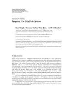
8.1. Comparison of one-step and three-step designs
For the following investigations, the average SNR ρ
(1)
of the
first channel from S1 to the RS is fixed at a certain value,
and the overall BER is depicted depending on the average
SNR ρ
(2)
of the second channel from S2 to the RS. It is as-
sumed that nodes S1 and S2 are each equipped with M
= 1
antenna and the RS is equipped with M
(RS)
= 2 antennas.
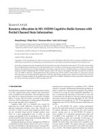
Figure 2 gives the overall BER performance for the linear ZF
and MMSE transceive filters from Section 3 which are either
designed in one step or in three steps. For the one-step de-
sign, β
= 0.5 is chosen since the optimization of the sum
rate is not of interest for the following investigations. For
all transceive filters, the BER performance has an error floor
which increases for decreasing ρ
(1)
, that is, all curves show
a saturation region where an increase of ρ
(2)
does no longer
improve the BER performance due to the fixed value of ρ
(1)
.
From receive and transmit oriented spatial filters, it is known
that the linear MMSE receive and transmit filters outperform
the linear ZF receive and transmit filters [24]. This result is
also found for the transceive filters in SDD relaying for the
one-step design which applies the same receive and transmit
filters like in [24]. The one-step and the three-step designs
10 EURASIP Journal on Advances in Signal Processing
10
−3
10
−2
10
−1
BER
0 5 10 15 20 25 30
ρ
(2)
(dB)
MMSE (three-step)
ZF (three-step
MMSE (one-step)
ZF (one-step)
Figure 2: Comparison of overall BER performance for the ZF
and MMSE transceive filters with one-step and three-step designs,
M
(1)
= M
(2)
= 1, M
(RS)
= 2 (dashed lines: ρ
(1)
= 10 dB, solid lines:
ρ
(1)
= 20 dB).
for the linear ZF transceive filter lead exactly to the same
BER performance. This has already been expected from the
derivation of the filters since both solutions simply reverse
the overall channels H
R
and H
T
. For the MMSE transceive
filter, the three-step design performs better than the one-step
design. This could also be expected from the design of the
filters since the one-step design does not consider the RS en-
ergy constraint in its optimization which leads to a subopti-
mum solution. Comparing (30)with(23)and(21), it can be
seen that the one-step MMSE transceive filter is a combina-
tionofaMMSEreceivefilterandaZFtransmitfilter.Thus,
the BER performance of the one-step MMSE transceive filter
is better than a three-step transceive filter consisting of a ZF
receive and a ZF transmit filter but worse than a three-step
transceive filter consisting of a MMSE receive and a MMSE
transmit filter.
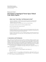
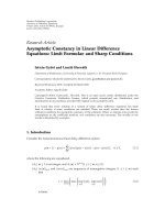
In the following, the BER performance of the MMSE
transceive filter from the three-step design is considered since
it provides the best results and its relative behavior is similar
to all other introduced transceive filters. Figure 3 gives the
overall BER performance depending on the number of an-
tennas at S1, S2, and RS. The result for M
(RS)
= 2 antennas at
the RS and M
(1)
= M
(2)
= 1 antenna at S1 and S2 is already
known from the Figure 2. Increasing the number of antennas
at RS leads to a significantly improved overall BER perfor-
mance which can be seen for the case M
(RS)
= 4andM
(1)
=
M
(2)
= 1. For this antenna configuration, the antenna beams
at the RS get tighter, that is, due to the higher degree of free-
dom at the RS the spatial separation of S1 and S2 by the linear
MMSE transceive filter can be improved. However, increas-
ing the number of antennas at S1 and S2 even degrades the
BER performance compared to the one-antenna case, that is,
M
(RS)
= 4andM
(1)
= M
(2)
= 2 provide a worse BER per-
10
−6
10
−5
10
−4
10
−3
10
−2
10
−1
BER
0 5 10 15 20 25 30
ρ
(2)
(dB)
M
(1)
= M
(2)
= 2, M
(RS)
= 4
M
(1)
= M
(2)
= 1, M
(RS)
= 2
M
(1)
= M
(2)
= 1, M
(RS)
= 4
Figure 3: Comparison of overall BER performance for the MMSE
transceive filter for different antenna configurations (dashed lines:
ρ
(1)
= 10 dB, solid lines: ρ
(1)
= 20 dB).
formance than M
(RS)
= 2andM
(1)
= M
(2)
= 1. This can be
explained by the analyses from Section 4. Here, it is shown
that for M
(1)
= M
(2)
≥ 2 additional intersymbol interference
among symbols of the same source appears. This intersymbol
interference does not exist for M
(1)
= M
(2)
= 1 and leads to
a degradation of the BER performance for M
(1)
= M
(2)
≥ 2.
This means that for SDD relaying, an increase of the number
of antennas at the RS improves the BER performance, but a
simultaneous increase of antennas at S1 and S2 will even de-
grade the BER performance in case of linear filtering at the
RS. Of course, if the additional antennas at S1 and S2 are
used for spatial diversity by space-time coding, for example,
the performance can be also improved. But these considera-
tions are beyond the scope of this paper.
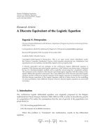
8.2. Subtraction of duplex-interference
Figure 4 gives the overall BER performance for the three-step
MMSE transceive filter with and without SDI as introduced
in Section 4 for M
(1)
= M
(2)
= 1, and M
(RS)
= 2, and
M
(RS)
= 4, respectively. Like the previous results, the BER
performance has an error floor which increases for decreas-
ing ρ
(1)
. There exists a significant improvement for the BER
performance for the linear MMSE transceive filter if SDI is
applied. For a target BER of 10
−2
, the SNR gain due to SDI
is approximately 4 dB for ρ
(1)
= 20 dB and M
(RS)
= 2. For
M
(RS)
= 4, there also exists an improvement of the BER per-
formance if SDI is applied. However, the SNR gain is much
lower than in case of M
(RS)
= 2. The higher number of an-
tennas at the RS provides a better spatial separation of S1
and S2 which directly reduces the duplex interference. This
means that for more than M
(RS)
= 2 antennas at the RS,
SDI does not provide a significant improvement and can be
T. Unger and A. Klein 11
10
−6
10
−5
10
−4
10
−3
10
−2
10
−1
BER
0 5 10 15 20 25 30
ρ
(2)
(dB)
MMSE without SDI, M
(RS)
= 2
MMSE without SDI, M
(RS)
= 4
MMSE with SDI, M
(RS)
= 2
MMSE with SDI, M
(RS)
= 4
Figure 4: Comparison of the overall BER performance for the
MMSE transceive filter with and without SDI for different numbers
of antennas at the RS, M
(1)
= M
(2)
= 1 (dashed lines: ρ
(1)
= 10 dB,
solid lines: ρ
(1)
= 20 dB).
0
1
2
3
4
5
6
Average sum rate (bit/s/Hz)
0 5 10 15 20 25 30
ρ
(2)
(dB)
ZF
MMSE without SDI
MMSE with SDI
Figure 5: Comparison of average sum rate for the ZF and MMSE
transceive filters with and without SDI, M
(1)
= M
(2)
= 1, M
(RS)
= 2
(dashed lines: ρ
(1)
= 10 dB, solid lines: ρ
(1)
= 20 dB).
neglected. In Figure 5, the average sum rates of the linear ZF
transceive filter, the three-step MMSE transceive filter with-
out SDI, and the three-step MMSE transceive filter with SDI
are given. Note that SDI cannot improve the performance
of the linear ZF transceive filter since the two channels are
perfectly orthogonalized by this filter which implicitly sup-
presses duplex interference at S1 and S2 at the cost of noise
0
0.5
1
1.5
2
2.5
3
Average rate (bit/s/Hz)
0 5 10 15 20 25 30
ρ
(2)
(dB)
Sum rate
Uplink
Downlink
Sum rate for β
app
Figure 6: Average sum rate and average rate of downlink and uplink
of MMSE transceive filter depending on ρ
(2)
for fixed ρ
(1)
= 10dB,
M
(1)
= M
(2)
= 1, M
(RS)
= 2 (solid lines: β from the optimization in
(41); dashed lines: β
= 0.5).
enhancement at the receivers. For increasing ρ
(2)
, the average
sum rate converges to a constant maximum which depends
on ρ
(1)
. For small ρ
(1)
, the sum rate converges faster with in-
creasing ρ
(2)
and the maximum sum rate is lower than for
high ρ
(1)
. For low ρ
(2)
, the linear ZF transceive filter has a
worse performance than the linear MMSE transceive filter.
If ρ
(1)
and ρ
(2)
are sufficiently high, the overall noise at S1
and S2 which consists of the noise at the RS and the noise
at S1 and S2 itself can be neglected. In this case, the sum
rate of the linear ZF transceive filter converges to the sum
rate of the MMSE transceive filter. This effect can already be
seen for ρ
(1)
= 20 dB and high values of ρ
(2)
.Itcanbeseen
from Figure 5 that SDI increases the sum rate for the MMSE
transceive filter if the SNR on both channels is low. For high
values of ρ
(1)
and ρ
(2)
, there exists almost no duplex inter-
ference and the sum rates of the MMSE transceive filter with
and without SDI converge.
8.3. Maximizing sum rate
In Section 7.1, maximizing the sum rate by giving different
weights to the RS estimation vectors in case of different
channel qualities on the two channels is discussed. In
Figure 6 for fixed ρ
(1)
= 10 dB, the average sum rate depend-
ing on ρ
(2)
of a three-step MMSE transceive filter achieved
for the numeric optimization of β
opt
from (41)iscompared
to the value achieved for fixed β
= 0.5 and the value achieved
by the approximation β
app
from (46). Additionally, the
rates of downlink and uplink for β
opt
and β = 0.5are
depicted separately. For equal channel qualities on both
channels (ρ
(1)
= ρ
(2)
), all approaches provide the same
average sum rate. However, for increasing difference of the
12 EURASIP Journal on Advances in Signal Processing
0
1
2
3
4
5
6
Average sum rate (bit/s/Hz)
0 5 10 15 20 25 30
ρ
(2)
(dB)
SDD relaying (MMSE)
MRC-BF relaying (MMSE)
MRC relaying
Figure 7: Comparison of average sum rate for SDD relaying, MRC
relaying, and MRC-BF relaying, M
(1)
= M
(2)
= 1, M
(RS)
= 2
(dashed lines: ρ
(1)
= 10 dB, solid lines: ρ
(1)
= 20 dB).
channel qualities on both channels, the sum rates diverge.
The optimization of β provides a higher sum rate than the
fixed approach with β
= 0.5. Let us consider the uplink for
ρ
(2)
> 10 dB, which means that the first hop of the uplink has
a higher SNR than the first hop of the downlink. Assigning
equal weights (β
= 0.5) to both RS estimation vectors results
in a lower rate in the uplink than in the downlink since the
second hop of the uplink has a lower SNR; but, if the RS
estimation vector of the uplink gets a higher weight due to
the optimization, then the situation changes and the uplink
achieves a higher rate than the downlink. In general, this
means that the sum rate may be increased by introducing a
higher weight to the RS estimation vector which is received
over the better channel on the first hop. This can be explained
as follows. The noise at the RS is filtered by the MMSE receive
filter which leads to different effective SNR values for the two
receive vectors from S1 and S2 after the filter. The receive
vector which comes over the better channel has a higher
SNR, provides a higher mutual information, and conse-
quently it should get a higher weight before retransmission.
The approximation for β
app
comes very close to the optimum
sum rate for β
opt
, although the approximation requires a
significantly lower effort than the optimum solution.
8.4. Average sum rate of different relaying schemes
In the following, the average sum rate of MRC relaying
and MRC-BF relaying with a linear MMSE transmit filter
is compared to the sum rate of SDD relaying with a linear
MMSE transceive filter at the RS. In Figure 7, the average sum
rate of the three schemes is depicted depending on ρ
(2)
for
ρ
(1)
= 10 dB and ρ
(1)
= 20 dB. Obviously, the linear MMSE
transceive filter in the SDD relaying approach outperforms
the MRC and MRC-BF relaying approaches in terms of aver-
age sum rate. This comes from the fact that in SDD relaying,
downlink and uplink signals are transmitted simultaneously.
In MRC relaying, downlink and uplink signals require sepa-
rated channel resources, and in MRC-BF relaying indeed the
number of required channel resources is decreased compared
to MRC relaying but still higher than in SDD relaying. There
exists a trade-off between the number of required channel
resources and the effective receive SNR at S1 and S2. SDD
relaying provides the worst effectivereceiveSNRsinceboth
antennas at the RS are used for spatial separation of down-
link and uplink signals. However, the reduced amount of re-
quired channel resources more than compensates the worst
effective receive SNR compared to the other schemes. MRC
provides the best effective receive SNR since both antennas
at the RS are used to improve the effective receive SNR, but
the improved effective receive SNR cannot compensate the
increased amount of required resources compared to SDD
relaying. The effective receive SNR and the number of re-
quired channel resources of MRC-BF relaying lie in-between
the values of MRC relaying and SDD relaying. However, this
trade-off in MRC-BF relaying seems to provide the worst per-
formance since it suffers from duplex interference in contrast
to MRC relaying.
9. CONCLUSION
In this paper, SDD relaying is proposed as a novel relay-
ing scheme saving channel resources for equal trafficloadin
downlink and uplink. In SDD relaying, downlink and uplink
signals are separated by applying transceive filters at the RS
which can be designed by a one-step or a three-step concept.
It turns out that the three-step transceive filters provide bet-
ter BER performances than the one-step filters and that the
three-step transceive filters are more flexible, for example, it
is only possible for the three-step transceive filters to give dif-
ferent weights to downlink and uplink signals which lead to
an increased sum rate. For a linear MMSE transceive filter,
duplex interference can be subtracted at S1 and S2 which re-
sults in an improved BER performance. The linear MMSE
transceive filters always outperform the linear ZF transceive
filters in terms of overall BER performance. The performance
of the transceive filters can be significantly improved by in-
creasing the number of antennas at the RS which allows a bet-
ter spatial separation of S1 and S2. For the sake of the com-
parison, MRC and MRC-BF relaying are proposed as other
relaying schemes which apply multiple antennas and linear
signal processing at the RS. It is shown that SDD relaying
provides a higher spectral efficiency than MRC and MRC-BF
relaying due to the simultaneous transmission of downlink
and uplink signals.
APPENDICES
A. DERIVATION OF ZF TRANSCEIVE FILTER
As shown in [26], the ZF optimization problem in (26a)is
not convex. However, the Karush-Kuhn-Tucker (KKT) con-
ditions [27]canbeusedtosolve(26a) under the constraints
T. Unger and A. Klein 13
(26b)and(26c). For simplicity but without loss of generality,
it is assumed that the scalar receive filters at S1 and S2 are the
same, that is, p
(1)
= p
(2)
= p. By applying the Lagrangian
function,
L(G, p, μ, Λ)
= tr
|p|
2
H
T
GR
n
RS
G
H
H
H
T
+ R
n
R
+ μ
tr
GR
y
RS
G
H
−
E
(RS)
−
2Re
tr
Λ
pH
T
GH
R
Q − I
,
(A.1)
the KKT conditions are given by
∂L(G, p, μ, Λ)
∂G
=|p|
2
H
∗
T
G
∗
R
∗
n
RS
H
T
T
+ μG
∗
R
∗
y
RS
− pQH
T
R
H
T
T
Λ
T
= 0,
(A.2a)
∂L(G, p, μ, Λ)
∂p
= tr
p
∗
H
T
GR
n
RS
G
H
H
H
T
− ΛH
T
GH
R
=
0,
(A.2b)
μ
tr
GR
y
RS
G
H
−
E
(RS)
=
0,
(A.2c)
Λ
pH
T
GH
R
Q − I
=
0.
(A.2d)
From the fourth KKT (A.2d), for det[Λ]
/
= 0onegets
G
=
1
p
H
H
T
H
T
−1
H
H
T
Q
H
H
H
R
H
R
H
H
H
R
−1
. (A.3)
Applying G from (A.3), p may be determined from the third
KKT (A.2c)forμ
/
= 0 leading to the solution given in (28).
B. DERIVATION OF MMSE TRANSCEIVE FILTER
As shown in [26], the MMSE optimization expression in
(29a) is not convex. In this case, the KKT conditions are only
required to solve (29a) under the transmit power constraint
(29b). For simplicity but without loss of generality, it is as-
sumed that the scalar receive filters at S1 and S2 are the same,
that is, p
(1)
= p
(2)
= p. By applying the Lagrangian function,
L(G, p, μ)
= tr
R
x
+ |p|
2
H
T
GH
R
QR
x
Q
H
H
H
R
G
H
H
H
T
− pH
T
GH
R
QR
x
− p
∗
R
x
Q
H
H
H
R
G
H
H
H
T
+tr{|p|
2
(H
T
GR
n
RS
G
H
H
H
T
+ R
n
R
)}
+ μ
tr
GR
y
RS
G
H
−
E
(RS)
,
(B.1)
the KKT conditions are given by
∂L(G, p, μ)
∂G
=|p|
2
H
∗
T
G
∗
R
∗
y
RS
H
T
T
− pR
T
x
Q
T
H
T
R
H
T
T
+ μG
∗
R
∗
y
RS
= 0,
(B.2a)
∂L(G, p, μ)
∂p
= tr{−H
T
GH
R
QR
x
+ p
∗
H
T
GR
y
RS
G
H
H
H
T
+ p
∗
R
n
R
}=0,
(B.2b)
μ(tr
{GR
y
RS
G
H
}−E
(RS)
) = 0.
(B.2c)
From the first KKT condition (B.2a) it can bee seen that there
exists no analytical solution for G due to the existence of the
power constraint (29b). Neglecting the power constraint in
(29b), the first KKT can be rewritten as
∂L(
G)
∂
G
= H
∗
T
G
∗
R
∗
y
RS
H
T
T
− R
T
x
Q
T
H
T
R
H
T
T
= 0. (B.3)
Solving (B.3)for
G, finally leads to
G =
H
H
T
H
T
−1
H
H
T
R
H
x
Q
H
H
H
R
R
−1
y
RS
. (B.4)
Introducing the normalization factor 1/pto (B.4)inorderto
fulfill the power constraint (29b) at the RS, subsequently one
gets
G
=
1
p
G (B.5)
with p from (31). Note that 1/p does not come from the op-
timization process itself, but it is a somehow artificial weight-
ing factor similar to the approach in [28].
ACKNOWLEDGEMENTS
Parts of this work have been presented at IST Mobile and
Wireless Communications Summit 2007 and at IEEE 18th
Symposium on Personal, Indoor, and Mobile Radio Com-
munications s(PIMRC 2007).
REFERENCES
[1] J.N.Laneman,D.N.C.Tse,andG.W.Wornell,“Cooperative
diversity in wireless networks: efficient protocols and outage
behavior,” IEEE Transactions on Information Theory, vol. 50,
no. 12, pp. 3062–3080, 2004.
[2] H. B
¨
olcskei, R. U. Nabar,
¨
O. Oyman, and A. J. Paulraj, “Ca-
pacity scaling laws in MIMO relay networks,” IEEE Transac-
tions on Wireless Communications, vol. 5, no. 6, pp. 1433–1444,
2006.
[3] P. W. C. Chan, E. S. Lo, R. R. Wang, et al., “The evolution path
of 4G networks: FDD or TDD?” IEEE Communications Maga-
zine, vol. 44, no. 12, pp. 42–50, 2006.
[4] C.S.Patel,G.L.St
¨
uber, and T. G. Pratt, “Statistical properties
of amplify and forward relay fading channels,” IEEE Transac-
tions on Vehicular Technology, vol. 55, no. 1, pp. 1–9, 2006.
[5] H. Shi, T. Asai, and H. Yoshino, “A relay node division duplex
relaying approach for MIMO relay networks,” in Proceedings of
the IEEE 17th Symposium on Personal, Indoor and Mobile Ra-
dio Communications (PIMRC ’07), pp. 1–5, Helsinki, Finland,
2006 September.
[6] A. Agust
´
ın, O. Mu
˜
noz, and J. Vidal, “A game theoretic ap-
proach for cooperative MIMO schemes with cellular reuse of
the relay slot,” in Proceedings of the IEEE International Confer-
ence on Acoustics, Speech and Signal Processing (ICASSP ’04),
vol. 4, pp. 581–584, Montreal, Quebec, Canada, May 2004.
[7] H. Hu, H. Yanikomeroglu, D. D. Falconer, and S. Periyalwar,
“Range extension without capacity penalty in cellular net-
works with digital fixed relays,” in Proceedings of the IEEE
Global Telecommunications Conference (GLOBECOM ’04),
vol. 5, pp. 3053–3057, Dallas, Tex, USA, November 2004.
14 EURASIP Journal on Advances in Signal Processing
[8] B. Rankov and A. Wittneben, “Spectral efficient protocols for
half-duplex fading relay channels,” IEEE Journal on Selected
Areas in Communications, vol. 25, no. 2, pp. 379–389, 2007.
[9]Y.Fan,C.Wang,J.Thompson,andH.V.Poor,“Recovering
multiplexing loss through successive relaying using repetition
coding,” IEEE Transactions on Wireless Communications,
vol. 6, no. 12, pp. 4484–4493, 2007.
[10] B. Rankov and A. Wittneben, “Spectral efficient signaling for
half-duplex relay channels,” in Proceedings of the 39th Annual
Asilomar Conference on Signals, Systems and Computers,pp.
1066–1071, Pacific Grove, Calif, USA, October-November
2005.
[11] T. J. Oechtering and H. Boche, “Bidirectional relaying using
interference cancellation,” in Proceedings of the ITG/IEEE In-
ternational Workshop on Smart Antennas (WSA ’07), Vienna,
Austria, 2007 February.
[12]R.Ahlswede,N.Cai,S Y.R.Li,andR.W.Yeung,“Network
information flow,” IEEE Transactions on Information Theory,
vol. 46, no. 4, pp. 1204–1216, 2000.
[13] P. Popovski and H. Yomo, “Wireless network coding by
amplify-and-forward for bi-directional trafficflows,”IEEE
Communications Letters , vol. 11, no. 1, pp. 16–18, 2007.
[14] P. Larsson, N. Johansson, and K E. Sunell, “Coded bi-
directional relaying,” in Proceedings of the IEEE 63rd Vehicular
Technology Conference (VTC ’06), vol. 2, pp. 851–855,
Melbourne, Australia, May 2006.
[15] Y. Fan and J. Thompson, “MIMO configurations for relay
channels: theory and practice,” IEEE Transactions on Wireless
Communications, vol. 6, no. 5, pp. 1774–1786, 2007.
[16] O. Mu
˜
noz-Medina, J. Vidal, and A. Agust
´
ın, “Linear trans-
ceiver design in nonregenerative relays with channel state
information,” IEEE Transactions on Signal Processing, vol. 55,
no. 6 I, pp. 2593–2604, 2007.
[17] M. Herdin, “MIMO amplify-and-forward relaying in corre-
lated MIMO channels,” in Proceedings of the 5th International
Conference on Information, Communications and Signal Proc-
essing (ICICS ’05), pp. 796–800, Bangkok, Thailand, Decem-
ber 2005.
[18] X. Tang and Y. Hua, “Optimal design of non-regenerative
MIMO wireless relays,” IEEE Transactions on Wireless
Communications, vol. 6, no. 4, pp. 1398–1407, 2007.
[19] O. Oyman and A. J. Paulraj, “Design and analysis of linear
distributed MIMO relaying algorithms,” IEE Proceedings-
Communications, vol. 153, no. 4, pp. 565–572, 2006.
[20] I. Hammerstr
¨
om, M. Kuhn, C. Esli, J. Zhao, A. Wittneben,
and G. Bauch, “MIMO two-way relaying with transmit CSI
at the relay,” in Proceedings of the IEEE 8th Workshop on Signal
Processing Advances in Wireless Communications (SPAWC ’07),
pp. 1–5, Helsinki, Finland, 2007 June.
[21] A. Paulraj, R. Nabar, and D. Gore, Introduction to Space-
Time Wireless Communications, Cambridge University Press,
Cambridge, UK, 1st edition, 2003.
[22] J. G. Proakis, Di gital Communications,McGraw-Hill,New
York, NY, USA, 4th edition, 2001.
[23] J. K. Cavers, “Single-user and multiuser adaptive maximal
ratio transmission for Rayleigh channels,” IEEE Transactions
on Vehicular Technology, vol. 49, no. 6, pp. 2043–2050, 2000.
[24] M. Joham, W. Utschick, and J. A. Nossek, “Linear transmit
processing in MIMO communication systems,”
IEEE Transac-
tions on Signal Processing, vol. 53, no. 8, pp. 2700–2712, 2005.
[25] P. Herhold, E. Zimmermann, and G. Fettweis, “On the perfor-
mance of cooperative amplify-and-forward relay networks,”
in Proceedings of the 5th International ITG Conference on
Source and Channel Coding (SCS ’04), Erlangen, Germany,
2004 January.
[26] M. Joham, “Optimization of linear and nonlinear transmit
signal processing,” Ph.D. thesis, Lehrstuhl f
¨
ur Netzwerktheo-
rie und Signalverarbeitung, Technische Universit
¨
at M
¨
unchen,
Munich, Germany, 2004.
[27] S. Boyd and L. Vandenberghe, Convex Optimization,Cam-
bridge University Press, Cambridge, UK, 1st edition, 2004.
[28] B. R. Vojcic and W. M. Jang, “Transmitter precoding in
synchronous multiuser communications,” IEEE Transactions
on Communications, vol. 46, no. 10, pp. 1346–1355, 1998.