Báo cáo hóa học: "Research Article Asymptotic Analysis of Large Cooperative Relay Networks Using Random Matrix Theory" pptx
Bạn đang xem bản rút gọn của tài liệu. Xem và tải ngay bản đầy đủ của tài liệu tại đây (914.13 KB, 15 trang )
Hindawi Publishing Corporation
EURASIP Journal on Advances in Signal Processing
Volume 2008, Article ID 235867, 15 pages
doi:10.1155/2008/235867
Research Article
Asymptotic Analysis of Large Cooperative Relay
Networks Using Random Matrix Theor y
Husheng Li,
1
Z. Han,
2
and H. Poor
3
1
Department of Electrical Engineering and Computer Science, The University of Tennessee, Knoxville, TN 37996-2100, USA
2
Department of Electrical and Computer Engineering, Boise State University, Boise, ID 83725, USA
3
Department of Electrical Engineering, Princeton University, Princeton, NJ 08544, USA
Correspondence should be addressed to Husheng Li,
Received 29 November 2007; Accepted 22 February 2008
Recommended by Andrea Conti
Cooperative transmission is an emerging communication technology that takes advantage of the broadcast nature of wireless
channels. In cooperative transmission, the use of relays can create a virtual antenna array so that multiple-input/multiple-output
(MIMO) techniques can be employed. Most existing work in this area has focused on the situation in which there are a small
number of sources and relays and a destination. In this paper, cooperative relay networks with large numbers of nodes are analyzed,
and in particular the asymptotic performance improvement of cooperative transmission over direction transmission and relay
transmission is analyzed using random matrix theory. The key idea is to investigate the eigenvalue distributions related to channel
capacity and to analyze the moments of this distribution in large wireless networks. A performance upper bound is derived, the
performance in the low signal-to-noise-ratio regime is analyzed, and two approximations are obtained for high and low relay-
to-destination link qualities, respectively. Finally, simulations are provided to validate the accuracy of the analytical results. The
analysis in this paper provides important tools for the understanding and the design of large cooperative wireless networks.
Copyright © 2008 Husheng Li et al. This is an open access article distributed under the Creative Commons Attribution License,
which permits unrestricted use, distribution, and reproduction in any medium, provided the original work is properly cited.
1. INTRODUCTION
In recent years, cooperative transmission [1, 2] has gained
considerable attention as a potential transmit strategy for-
wireless networks. Cooperative transmission efficiently takes
advantage of the broadcast nature of wireless networks, and
also exploits the inherent spatial and multiuser diversities
of the wireless medium. The basic idea of cooperative
transmission is to allow nodes in the network to help
transmit/relay information for each other, so that cooper-
ating nodes create a virtual multiple-input/multiple-output
(MIMO) transmission system. Significant research has been
devoted to the design of cooperative transmission schemes
and the integration of this technique into cellular, WiFi,
Bluetooth, ultrawideband, Worldwide Interoperability for
MicrowaveAccess(WiMAX),andadhocandsensornet-
works. Cooperative transmission is also making its way into
wireless communication standards, such as IEEE 802.16j.
Most current research on cooperative transmission
focuses on protocol design and analysis, power control, relay
selection, and cross-layer optimization. Examples of repre-
sentative work are as follows. In [3], transmission protocols
for cooperative transmission are classified into different types
and their performance is analyzed in terms of outage proba-
bilities. The work in [4] analyzes more complex transmitter
cooperative schemes involving dirty paper coding. In [5],
centralized power allocation schemes are presented, while
energy-efficient transmission is considered for broadcast
networks in [6]. In [7], oversampling is combined with
the intrinsic properties of orthogonal frequency division
multiplexing (OFDM) symbols, in the context of maximal
ratio combining (MRC) and amplify-and-forward relaying,
so that the rate loss of cooperative transmission can be
overcome. In [8], the authors evaluate cooperative-diversity
performance when the best relay is chosen according to
the average signal-to-noise ratio (SNR), and the outage
probability of relay selection based on the instantaneous
SNR. In [9], the authors propose a distributed relay selection
scheme that requires limited network knowledge and is
based on instantaneous SNRs. In [10], sensors are assigned
for cooperation so as to reduce power consumption. In
[11], cooperative transmission is used to create new paths
2 EURASIP Journal on Advances in Signal Processing
so that energy depleting critical paths can be bypassed.
In [12], it is shown that cooperative transmission can
improve the operating point for multiuser detection so that
multiuser efficiency can be improved. Moreover, network
coding is also employed to improve the diversity order and
bandwidth efficiency. In [13], a buyer/seller game is proposed
to circumvent the need for exchanging channel information
to optimize the cooperative communication performance.
In [14], it is demonstrated that boundary nodes can help
backbone nodes’ transmissions using cooperative transmis-
sion as future rewards for packet forwarding. In [15], auction
theory is explored for resource allocation in cooperative
transmission.
Most existing work in this area analyzes the performance
gain of cooperative transmission protocols assuming small
numbers of source-relay-destination combinations. In [16],
large relay networks are investigated without combining
of source-destination and relay-destination signals. In [17],
transmit beamforming is analyzed asymptotically as the
number of nodes increases without bound. In this paper,
we analyze the asymptotic (again, as the number of nodes
increases) performance improvement of cooperative trans-
mission over direct transmission and relay transmission.
Relay nodes are considered in this paper while only beam-
forming in point-to-point communication is considered in
[17]. Unlike [16], in which only the indirect source-relay-
destination link is considered, we consider the direct link
from source nodes to destination nodes. The primary tool
we will use is random matrix theory [18, 19]. The key
idea is to investigate the eigenvalue distributions related to
capacity and to analyze their moments in the asymptote
of large wireless networks. Using this approach, we derive
a performance upper bound, we analyze the performance
in the low signal-to-noise-ratio regime, and we obtain
approximations for high and low relay-to-destination link
qualities. Finally, we provide simulation results to validate
the analytical results.
This paper is organized as follows. In Section 2, the
system model is given, while the basics of random matrix
theory are discussed in Section 3.InSection 4,weanalyze
the asymptotic performance and construct an upper bound
for cooperative relay networks using random matrix theory.
Some special cases are analyzed in Section 5, and simulation
results are discussed in Section 6. Finally, conclusions are
drawn in Section 7.
2. SYSTEM MODEL
We consider the system model shown in Figure 1.Suppose
there are M source nodes, M destination nodes, and K
relay nodes. Denote by H, F,andG the channel matri-
ces of source-to-relay, relay-to-destination, and source-to-
destination links, respectively, so that H is M
×K, F is K ×M,
and G is M
× M. Transmissions take place in two stages.
Further denote the thermal noise at the relays by the K-
vector z, the noise in the first stage at the destination by
the M-vector w
1
and the noise in the second stage at the
destination by the M-vector w
2
. For simplicity of notation,
we assume that all of the noise variables have the same power
K relays
Stage 1 Stage 2
S
1
S
2
S
M
D
1
D
2
D
M
Figure 1: Cooperative transmission system model.
and denote this common value by σ
2
n
, the more general case
being straightforward. The signals at the source nodes are
collected into the M-vector s. We assume that the transmit
power of each source node and each relay node is given by
P
s
and P
r
, respectively. For simplicity, we further assume
that matrices H, F,andG have independent and identically
distributed (i.i.d.) elements whose variances are normalized
to 1/K,1/M,and1/M, respectively. Thus, the average norm
of each column is normalized to 1; otherwise the receive
SNR at both relay nodes and destination nodes will diverge
in the large system limit. (Note that we do not specify the
distribution of the matrix elements since the large system
limit is identical for most distributions, as will be seen
later.) The average channel power gains, determined by path
loss, of source-to-relay, source-to-destination, and relay-to-
destination links are denoted by g
sr
, g
sd
,andg
rd
,respectively.
Using the above definitions, the received signal at the
destination in the first stage can be written as
y
sd
=
g
sd
P
s
Gs + w
1
,(1)
and the received signal at the relays in the first stage can be
written as
y
sr
=
g
sr
P
s
Hs + z. (2)
If an amplify-and-forward protocol [16] is used, the received
signal at the destination in the second stage is given by
y
rd
=
g
rd
g
sr
P
r
P
s
P
0
FHs +
g
rd
P
r
P
0
Fz + w
2
,(3)
where
P
0
=
g
sr
P
s
K
trace
HH
H
+ σ
2
n
,(4)
namely, the average received power at the relay nodes, which
is used to normalize the received signal at the relay nodes so
that the average relays transmit power equals P
r
. To see this,
Husheng Li et al. 3
we can deduce the transmitted signal at the relays, which is
given by
t
rd
=
g
sr
P
r
P
s
P
0
Hs +
P
r
P
0
z. (5)
Then, the average transmit power is given by
1
K
trace
E
t
rd
t
H
rd
=
1
K
trace
g
sr
P
r
P
s
P
0
HH
H
+
P
r
σ
2
n
P
0
I
=
P
r
KP
0
trace
g
sr
P
s
HH
H
+ σ
2
n
I
=
P
r
,
(6)
where the last equation is due to (4).
Combining the received signal in the first and second
stages, the total received signal at the destination is a 2M-
vector:
y
= Ts + w,(7)
where
T
=
⎛
⎜
⎜
⎜
⎝
g
sd
P
s
G
g
sr
g
rd
P
r
P
s
P
0
FH
⎞
⎟
⎟
⎟
⎠
,
w
=
⎛
⎜
⎜
⎝
w
1
g
rd
P
r
P
0
Fz + w
2
⎞
⎟
⎟
⎠
.
(8)
Thesumcapacityofthissystemisgivenby
C
sum
= log det
I + T
H
E
−1
ww
H
T
=
log det
⎡
⎢
⎢
⎣
I+
g
sd
P
s
G
H
,
g
sr
g
rd
P
r
P
s
P
0
H
H
F
H
×
⎛
⎜
⎝
σ
2
n
I 0
0 σ
2
n
I+
g
rd
P
r
P
0
FF
H
⎞
⎟
⎠
−1
⎛
⎜
⎜
⎝
g
sd
P
s
G
g
sr
g
rd
P
r
P
s
P
0
FH
⎞
⎟
⎟
⎠
⎤
⎥
⎥
⎦
=
log det
I +
g
sd
P
s
σ
2
n
G
H
G
+
g
sr
g
rd
P
r
P
s
P
0
σ
2
n
H
H
F
H
I +
g
rd
P
r
P
0
FF
H
−1
FH
=
log det
I + γ
1
G
H
G + βγ
2
H
H
F
H
I + βFF
H
−1
FH
.
(9)
Here γ
1
g
sd
P
s
/σ
2
n
and γ
2
g
sr
P
s
/σ
2
n
represent the
SNRs of the source-to-destination and source-to-relay links,
respectively, and β g
rd
P
r
/P
0
is the amplification ratio of
the relay.
We use a simpler notation for (9), which is given by
C
sum
= log det(I + Ω) = log det
I + Ω
s
+ Ω
r
, (10)
where Ω
s
γ
1
G
H
G corresponds to the direct channel from
the source to the destination; and
Ω
r
βγ
2
H
H
F
H
I + βFF
H
−1
FH (11)
corresponds to the signal relayed to the destination by the
relay nodes. On denoting the eigenvalues of the matrix Ω by
{λ
Ω
m
}
m=1,2,
, the sum capacity C
sum
can be written as
C
sum
=
M
m=1
log
1+λ
Ω
m
. (12)
In the following sections, we obtain expressions or approxi-
mations for C
sum
by studying the distribution of λ
Ω
m
.
We are interested in the average channel capacity of the
large relay network, which is defined as
C
avg
1
M
C
sum
. (13)
In this paper, we focus on analyzing C
avg
in the large system
scenario, namely, K, M
→∞while α M/K is held constant,
which is similar to the large system analysis arising in the
study of code division multiple access (CDMA) systems [20].
Therefore, we place the following assumption on C
avg
.
Assumption 1.
C
avg
−→ E
log
1+λ
Ω
, almost surely, (14)
where λ
Ω
is a generic eigenvalue of Ω,asK, M →∞.
This assumption will be validated by the numerical result
in Section 6, which shows that the variance of C
avg
decreases
to zero as K and M increase. In the remaining part of this
paper, we consider C
avg
to be a constant in the sense of the
large system limit, unless noted otherwise.
3. BASICS OF LARGE RANDOM MATRIX THEORY
In this section, we provide some basics of random matrix
theory, including the notions of noncrossing partitions,
isomorphic decomposition, combinatorial convolution, and
free cumulants, which provide analytical machinery for
characterizing the average channel capacity when the system
dimensions increase asymptotically.
3.1. Freeness
Below is the abstract definition of freeness, which is origi-
nated by Voiculescu [21–23].
Definition 1. Let A be a unital algebra equipped with a
linear functional ψ : A
→ C, which satisfies ψ(1) = 1.
Let p
1
, , p
k
be one-variable polynomials. We call elements
a
1
, , a
m
∈ A free if for all i
1
/
=i
2
/
=···
/
=i
k
,wehave
ψ
p
1
a
i
1
···p
k
a
i
k
= 0, (15)
4 EURASIP Journal on Advances in Signal Processing
whenever
ψ
p
j
a
i
j
=
0, ∀j = 1, , k. (16)
In the theory of large random matrices, we can consider
random matrices as elements a
1
, , a
m
, and the linear
functional ψ maps a random matrix A to the expectation of
eigenvalues of A.
3.2. Noncrossing partitions
A partition of a set
{1, , p} is defined as a division of the
elements into a group of disjoint subsets, or blocks (a block
is termed an i-block when the block size is i). A partition is
called an r-partition when the number of blocks is r.
We say that a partition of a p-set is noncrossing if, for any
two blocks
{u
1
, , u
s
} and {v
1
, , v
t
},wehave
u
k
<v
1
<u
k+1
⇐⇒ u
k
<v
t
<u
k+1
, ∀k = 1, , s, (17)
with the convention that u
s+1
= u
1
. For example, for the set
{1, 2, 3,4,5, 6, 7,8}, {{1, 4, 5, 6}, {2, 3}, {7}, {8}}is noncross-
ing, while
{{1, 3, 4,6},{2, 5}, {7}, {8}} is not. We denote the
set of noncrossing partitions on the set
{1, 2, , p} by NC
p
.
3.3. Isomorphic decomposition
The set of noncrossing partitions in
NC
p
has a partial
ordering structure, in which π
≤ σ if each block of π is a
subset of a corresponding block of σ.Then,foranyπ
≤ σ ∈
NC
p
, we define the interval between π and σ as
[π, σ]
ψ ∈ NC
p
| π ≤ ψ ≤ σ
. (18)
It is shown in [21] that, for all π
≤ σ ∈ NC
p
, there exists
a canonical sequence of positive integers
{k
i
}
i∈N
such that
[π, σ]
∼
=
j∈N
NC
k
j
j
, (19)
where
∼
=
is an isomorphism (the detailed mapping which can
be found in the proof of Proposition 1 in [21]), the product
is the Cartesian product, and
{k
j
}
j∈N
is called the class of
[π, σ].
3.4. Incidence algebra, multiplicative function,
and combinatorial convolution
The incidence algebra on the partial ordering structure of
NC
p
is defined as the set of all complex-valued functions
f (ψ, σ) with the property that f (ψ, σ)
= 0ifψ σ [20].
The combinatorial convolution between two functions f
and g in the incidence algebra is defined as
f g(π, σ)
π≤ψ≤σ
f (π, ψ)g(ψ, σ), ∀π ≤ σ. (20)
An important subset of the incidence algebra is the set of
multiplicative functions f on [π, σ], which are defined by the
property
f (π, σ)
j∈N
a
k
j
j
, (21)
where
{a
j
}
j∈N
is a series of constants associated with
f , and the class of [π, σ]is
{k
j
}
j∈N
.Wedenotebyf
a
the multiplicative function with respect to {a
j
}
j∈N
.An
important function in the incidence algebra is the zeta
function ζ,whichisdefinedas
ζ(π, σ)
⎧
⎨
⎩
1, if ψ ≤ σ,
0, else.
(22)
Further, the unit function I on the incidence algebra is
defined as
I(π, σ)
⎧
⎨
⎩
1, if ψ = σ,
0, else.
(23)
The inverse of the ζ function, denoted by μ,withrespect
to combinatorial convolution, namely, μ ζ
= I,istermed
the M
¨
obius function.
3.5. Moments and free cumulants
Denote the pth moment of the (random) eigenvalue λ by
m
p
E[λ
p
]. We introduce a family of quantities termed
free cumulants [22]denotedby
{k
p
} for Ω where pdenotes
the order. We will use a superscript to indicate the matrix
for which the moments and free cumulants are defined.
The relationship between moments and free cumulants is
given by combinatorial convolution in the incidence algebra
[21, 22], namely,
f
m
= f
k
ζ,
f
k
= f
m
μ,
(24)
where the multiplicative functions f
m
(characterizing the
moments), f
k
(characterizing the free cumulants), zeta func-
tion ζ,M
¨
obius function μ, and combinatorial convolution
are defined above.
By applying the definition of a noncrossing partition,
(24), can be translated into the following explicit forms for
the first three moments and free cumulants:
m
1
= k
1
,
m
2
= k
2
+ k
2
1
,
m
3
= k
3
+3k
1
k
2
+ k
3
1
,
k
1
= m
1
,
k
2
= m
2
−m
2
1
,
k
3
= m
3
−3m
1
m
2
+2m
3
1
.
(25)
The following lemma provides the rules for the addition
[22](see(B.4)) and product [22](see(D.9)) of two free
matrices.
Lemma 1. If matrices A and B are mutually free, one has
f
k
A+B
= f
k
A
+ f
k
B
, (26)
f
k
AB
= f
k
A
f
k
B
.
(27)
Husheng Li et al. 5
4. ANALYSIS USING RANDOM MATRIX THEORY
It is difficult to obtain a closed-form expression for the
asymptotic average capacity C
avg
in (13). In this section,
using the theory of random matrices introduced in the
last section, we first analyze the random variable λ
Ω
by
characterizing its moments and providing an upper bound
for C
avg
.Then,wecanrewriteC
avg
in terms of a moment
series, which facilitates the approximation.
4.1. Moment analysis of λ
Ω
In contrast to [16], we analyze the random variable C
avg
via
its moments, instead of its distribution function, because
moment analysis is more mathematically tractable. For
simplicity, we denote βF
H
(I + βFF
H
)
−1
F by Γ,whichis
obviously Hermitian. Then, the matrix Ω is given by
Ω
= γ
1
G
H
G + γ
2
H
H
ΓH. (28)
In order to apply free probability theory, we need as a
prerequisite that G
H
G, H
H
H,andF
H
(I + βFF
H
)
−1
F be
mutually free (the definition of freeness can be found in
[23]). It is difficult to prove the freeness directly. However,
the following proposition shows that the result obtained
from the freeness assumption coincides with [24,Theorem
1.1] (same as in (29)) in [24], which is obtained via an
alternative approach.
Proposition 1. Suppose γ
1
= γ
2
= 1 (note that the
assumption γ
1
= γ
2
= 1 is for convenience of analysis; it
is straightforward to extend the proposition to general cases).
Based on the freeness assumption, the Stieltjes transform of the
eigenvalues in the matrix Ω satisfies the following Marc
˘
enko-
Pastur equation:
m
Ω
(z) = m
G
H
G
z −
1
α
τdF (τ)
1+τ(z)m
Ω
(z)
, (29)
where F is the probability distribution function of the
eigenvalues of the matrix Γ,andm(z) denotes the Stieltjes
transform [20].
Proof. See Appendix A.
Therefore, we assume that these matrices are mutually
free (the freeness assumption) since this assumption yields the
same result as a rigorously proved conclusion. The validity
of the assumption is also supported by numerical results
included in Section 6. Note that the reason why we do not
apply the conclusion in Proposition 1 directly is that it is
easier to manipulate using the moments and free probability
theory.
Using the notion of multiplicative functions and
Lemma 1, the following proposition characterizes the free
cumulants of the matrix Ω, based upon which we can
compute the eigenvalue moments of Ω from (24)(or(25)
explicitly for the first three moments).
Proposition 2. The free cumulants of the matrix Ω in (28) are
given by
f
k
Ω
= f
k
Ω
s
+
f
k
Γ
f
k
H
ζ
δ
1/α
μ, (30)
where k
Ω
s
p
= 1,thefreecumulantofk
H
p
= γ
p
2
/α, ∀p ∈ N ,
H = γ
2
HH
H
, and the multiplicative function δ
1/α
is defined as
δ
1/α
(τ, π) =
⎧
⎪
⎪
⎨
⎪
⎪
⎩
1
α
, if τ
= π;
0, if τ
/
=π.
(31)
Proof. The proof is straightforward by applying the relation-
ship between free cumulants and moments. The reasoning is
given as follows:
(i) f
k
Γ
f
k
H
represents the free cumulants of the matrix
γ
2
ΓHH
H
(applying Lemma 1);
(ii) ( f
k
Γ
f
k
H
)ζ represents the moments of the matrix
γ
2
ΓHH
H
;
(iii) (( f
k
Γ
f
k
H
) ζ) δ
1/α
represents the moments of
the matrix γ
2
H
H
ΓH;
(iv) ((( f
k
Γ
f
k
H
) ζ) δ
1/α
) μ represents the free
cumulants of the matrix γ
2
H
H
ΓH;
(v) the final result is obtained by applying Lemma 1.
4.2. Upper bound of average capacity
Although in Section 4.1 we obtained all moments of λ
Ω
,
we did not obtain an explicit expression for the average
channel capacity. However, we can provide an upper bound
on this quantity by applying Jensen’s inequality, which we
summarize in the following proposition.
Proposition 3. The average capacity satisfies
C
(u)
avg
≤ log
1+γ
1
+
αβγ
2
α + β
. (32)
Proof. By applying Jensen’s inequality, we have
E
log
1+λ
Ω
≤
log
1+E
λ
Ω
=
log
1+E
λ
Ω
s
+ E
λ
Ω
r
.
(33)
From [20], we obtain
E
λ
Ω
s
=
γ
1
. (34)
For Ω, we can show
E
λ
Ω
r
=
1
α
E
λ
Ω
r
, (35)
where
Ω
r
= βγ
2
F
H
I + βFF
H
−1
FHH
H
. (36)
By applying the law of matrix product in Lemma 1,we
can further simplify (35)to
E
λ
Ω
r
=
γ
2
α
E
λ
HH
H
E
λ
Γ
=
γ
2
E
λ
HH
H
E
βλ
FF
H
1+βλ
FF
H
.
(37)
6 EURASIP Journal on Advances in Signal Processing
By applying Jensen’s inequality again, we have
E
λ
Ω
r
≤
γ
2
E
λ
HH
H
βE
λ
FF
H
1+βE
λ
FF
H
=
αβγ
2
α + β
, (38)
where we have applied the facts E[λ
HH
H
] = α and E[λ
FF
H
] =
1/α.
Combining the above equations yields the upper bound
in (32).
4.3. Expansion of average capacity
In addition to providing an upper bound on the average
capacity, we can also expand C
avg
into a power series so that
the moment expressions obtained from Proposition 2 can be
applied. Truncating this power series yields approximations
for the average capacity.
In particular, by applying a Taylor series expansion
around a properly chosen constant x
0
, C
avg
can be written
as
C
avg
= log
1+x
0
+
∞
k=1
(−1)
k−1
E
λ −x
0
k
k
1+x
0
k
. (39)
Taking the first two terms of the series yields the approxima-
tion
C
avg
≈ log
1+x
0
+
m
1
−x
0
1+x
0
−
m
2
−2x
0
m
1
+ x
2
0
2
1+x
0
2
. (40)
We c an s et x
0
= γ
1
+ αβγ
2
/(α + β), which is an upper bound
for E[λ
Ω
] as shown in Proposition 3. We can also set x
0
=
0 and obtain an approximation when λ
Ω
is small.Equations
(40) will be a useful approximation for C
avg
in Sections 5.2
and 5.3 when β is large or small or when SNR is small.
5. APPROXIMATIONS OF C
avg
In this section, we provide explicit approximations to C
avg
for
several special cases of interest. The difficulty in computing
C
avg
lies in determining the moments of the matrix Γ.
Therefore, in the low SNR region (Section 5.1), we consider
representing C
avg
in terms of the average capacities of
the source-destination link and the source-relay-destination
link. Then, we consider the region of high (Section 5.2)or
low β (Section 5.3), where Γ can be simplified; thus we will
obtain approximations in terms of α, β, γ
1
,andγ
2
. Finally,
higher-order approximation will be studied in Section 5.4.
5.1. Approximate analysis in the low SNR regime
Unlike Section 4 which deals with general cases, we assume
here that both the source-to-destination and relay-to-
destination links within the low SNR regime, that is, P
s
/σ
2
n
and P
r
/σ
2
n
are small. Such an assumption is reasonable when
both source nodes and relay nodes are far away from the
destination nodes.
Within the low-SNR assumption, the asymptotic average
capacity can be expanded in the Taylor series expansion
about x
0
= 0in(40), which is given by
C
avg
= E
log
1+λ
Ω
=
∞
i=1
(−1)
i+1
m
Ω
i
i
. (41)
We denote the pth-order approximation of C
avg
by
C
p
=
p
i=1
(−1)
i+1
m
Ω
i
i
, (42)
which implies
m
Ω
i
= (−1)
i+1
i
C
i
−C
i−1
. (43)
We den ote by
{C
s
p
} and {C
r
p
} the average capacity
approximations (the same as in (42)) for the source-
destination link and the source-relay-destination link,
respectively. Our target is to represent the average capacity
approximations
{C
p
} by using {C
s
p
} and {C
r
p
} under the
low-SNR assumption, which reveals the mechanism of
information combining of the two links.
By combining (25), (26), and (43), we can obtain
C
1
= C
s
1
+ C
r
1
,
C
2
= C
s
2
+ C
r
2
−C
s
1
C
r
1
,
C
3
= C
s
3
+ C
r
3
−C
s
1
C
r
1
+4C
s
1
C
r
1
−2C
s
1
C
r
2
−2C
r
1
C
s
2
,
(44)
where C
s
p
and C
r
p
denote the pth-order approximations of
the average capacity of the source-destination link and the
source-relay-destination link, respectively.
Equation (44) shows that, to a first-order approximation,
the combined effect of the source-destination and source-
relay-destination links is simply a linear addition of average
channel capacities, when the low-SNR assumption holds. For
the second-order approximation in (44), the average capacity
is reduced by a nonlinear term C
s
1
C
r
1
. The third-order term in
(44) is relatively complicated to interpret.
5.2. High β region
In the high β region, the relay-destination link has a better
channel than that of the source-relay link. The following
proposition provides the first two moments of the eigenval-
ues λ in Ω in this case.
Proposition 4. As β
→∞, the first two moments of the
eigenvalues λ in Ω converge to
m
1
=
⎧
⎨
⎩
γ
1
+ αγ
2
, if α ≤ 1,
γ
1
+ γ
2
, if α>1,
m
2
=
⎧
⎨
⎩
2
γ
2
1
+ αγ
2
2
+ αγ
1
γ
2
, if α ≤ 1,
2γ
2
1
+2γ
1
γ
2
+ γ
2
2
(1 + α), if α>1.
(45)
Proof. See Appendix B.
Husheng Li et al. 7
5.3. Low β region
In the low β region, the source-relay link has a better channel
than the relay-destination link does. Similar to the result
of Section 5.2, the first two eigenvalue moments of Ω are
provided in the following proposition, which can be used to
approximate C
avg
in (40).
Proposition 5. Suppose βγ
2
= D.Asβ → 0 and D remains
a constant, the first two mome nts of the eigenvalues λ in Ω
converge to
m
1
= γ
1
+ D,
m
2
= 2γ
2
1
+2γ
1
D + D
2
(α +2).
(46)
Proof. See Appendix C.
5.4. Higher-order approximations for
high and low β regions
In the previous two subsections, taking a first order
approximation of the matrix Γ
= βF
H
(I + βFF
H
)
−1
F
resulted in simple expressions for the moments. We can also
consider higher-order approximations, which provide finer
expressions for the moments. These results are summarized
in the following proposition, a proof of which is given in
Appendix D. Note that m
1
and m
2
denote the first-order
approximations given in Propositions 4 and 5,and
m
1
and
m
2
denote the expressions after considering higher-order
terms. Note that, when β is large, we do not consider the case
α
= 1 since the matrix FF
H
is at a critical point in this case,
that is, for any α<1, FF
H
is of full rank almost surely; for
any α>1, FF
H
is singular.
Proposition 6. For sufficiently small β, one has
m
1
= m
1
−γ
2
β
2
1+
1
α
+ o
β
2
,
m
2
= m
2
−2γ
2
β
2
γ
1
+ βγ
2
1+
1
α
+ o
β
2
.
(47)
For sufficiently large β and α<1, one has
m
1
= m
1
−
γ
2
α
2
β(1 −α)
+ o
1
β
,
m
2
= m
2
−
2γ
2
α
2
γ
1
+ αγ
2
β(1 −α)
+ o
1
β
.
(48)
For sufficiently large β and α>1, one has
m
1
= m
1
−
αγ
2
β(α − 1)
+ o
1
β
,
m
2
= m
2
−
2γ
2
α
γ
1
+ γ
2
β(α − 1)
+ o
1
β
.
(49)
Proof. See Appendix D.
0
0.02
0.04
0.06
0.08
0.1
0.12
Va ri an ce o f C
avg
4 6 8 101214161820
K
α
= 0.5
α
= 1
α
= 2
Figure 2: Variance of C
avg
versus different K.
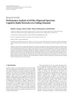
6. SIMULATION RESULTS
In this section, we provide simulation results to validate the
analytical results derived in the previous sections. Figure 2
shows the variance of C
avg
normalized by E
2
[C
avg
]versusK.
The configuration used here is γ
1
= 1, γ
2
= 10, β = 1, and
α
= 0.5/1/2. For each value of K, we obtain the variance
of C
avg
by averaging over 1000 realizations of the random
matrices, in which the elements are mutually independent
complex Gaussian random variables. We can observe that the
variance decreases rapidly as K increases. When K is larger
than 10, the variance of C
avg
is very small. This supports the
validity of Assumption 1.
In the following simulations, we fix the value of K to be
40. All accurate values of average capacities C
avg
are obtained
from 1000 realizations of the random matrices. Again, the
elements in these random matrices are mutually indepen-
dent complex Gaussian random variables. All performance
bounds and approximations are computed by the analytical
results obtained in this paper.
Figure 3 compares the accurate average capacity obtained
from (9) and the first three orders of approximation given
in (44)withγ
1
ranging from 0.01 to 0.1. We set γ
2
= γ
1
and β = 1. From Figure 3, we observe that, in the low-SNR
region, the approximations approach the correct values quite
well. The reason is that the average capacity is approximately
linear in the eigenvalues when SNR is small, which makes
our expansions more precise. When the SNR becomes larger,
the approximations can be used as bounds for the accurate
values. (Notice that the odd orders of approximation provide
upper bounds while the even ones provide lower bounds.)
In Figure 4, we plot the average capacity versus α,
namely the ratio between the number of source nodes (or
equivalently, destination nodes) and the number of relay
nodes. The configuration is γ
1
= 0.1, γ
2
= 10, and β = 10.
8 EURASIP Journal on Advances in Signal Processing
0
0.1
0.2
0.3
0.4
0.5
0.6
0.7
Average capacity (bits/s/Hz)
0.02 0.04 0.06 0.08 0.1
γ
1
Accurate
1st order
2nd order
3rd order
Figure 3: Comparison of different orders of approximation.
1
1.5
2
2.5
3
3.5
4
4.5
Average capacity (bits/s/Hz)
0.20.40.60.811.21.41.61.8
α
Accurate
Upper bound
Figure 4: Performance versus various α.
We observe that the average capacity achieves a maximum
when α
= 1, namely, when using the same number of relay
nodes as the source/destination nodes. A possible reason for
this phenomenon is the normalization of elements in H.
(Recall that the variance of elements in H is
1/K
such that
the norms of column vectors in H are 1.) Now, suppose that
M is fixed. When α is small, that is, K is large, the receive SNR
at each relay node is small, which impairs the performance.
When α is large, that is, K is small, we lose degrees of
freedom. Therefore, α
= 1 achieves the optimal tradeoff.
However, in practical systems, when the normalization is
10
0
10
1
10
2
10
3
Moments
0.20.40.60.811.21.41.6
α
m
1
m
2
1st order m
1
1st order m
2
2nd order m
1
2nd order m
2
Figure 5: Eigenvalue moments versus various α in the high β
region.
2
4
6
8
10
12
14
16
Moments
0.20.40.60.811.21.41.6
α
m
1
m
2
1st order m
1
1st order m
2
2nd order m
1
2nd order m
2
Figure 6: Eigenvalue moments versus various α in the low β region.
removed, it is always better to have more relay nodes if the
corresponding cost is ignored. We also plot the upper bound
in (32),whichprovidesalooseupperboundhere.
In Figures 5 and 6, we plot the precise values of m
1
and m
2
obtained from simulations and the corresponding
first- and second-order approximations. The configuration
is β
= 10 (Figure 5)orβ = 0.1(Figure 6), γ
1
= 2andγ
2
=
10. We can observe that the second-order approximation
outperforms the first-order approximation except when α is
close to 1 and β is large. (According to Proposition 6, the
approximation diverges as α
→ 1andβ →∞.)
Husheng Li et al. 9
1.4
1.6
1.8
2
2.2
2.4
2.6
Average capacity (bits/s/Hz)
0.20.40.60.811.21.41.6
α
Accurate
1st order approximation
2nd order approximation
Figure 7: Performance versus various α in the high β region.
In Figure 7, we plot the average capacity versus α in the
high β region, with configuration β
= 10, γ
1
= 2, and
γ
2
= 10. We can observe that the Taylor expansion provides a
good approximation when α is small. Similar to Figure 7, the
second-order approximation outperforms the first-order one
except when α is close to 1. In Figure 8, we plot the average
capacity versus α in the low β region. The configuration is the
same as that in Figure 7 except that β
= 0.1. We can observe
that the Taylor expansion provides a good approximation
for both small and large α. However, unlike the moment
approximation, the error of the second-order approximation
is not better than that of the first-order approximation.
This is because (40) is also an approximation, and bet-
ter approximation of the moments does not necessarily
lead to a more precise approximation for the average
capacity.
In Figure 9, we plot the ratio between the average
capacity in (9) and the average capacity when the signal from
the source to the destination in the first stage is ignored,
as a function of the ratio γ
1
/γ
2
. We test four combinations
of γ
2
and β. (Note that α = 0.5.) We observe that the
performance gain increases with the ratio γ
1
/γ
2
(the channel
gain ratio between source-destination link and source-relay
link). The performance gain is substantially larger in the low-
SNR regime (γ
2
= 1) than in the high-SNR regime (γ
2
= 10).
When the amplification ratio β decreases, the performance
gain is improved. Therefore, substantial performance gain is
obtained by incorporating the source-destination link when
the channel conditions of the source-destination link are
comparable to those of the relay-destination link and the
source-relay link, particularly in the low-SNR region. In
other cases, we can simply ignore the source-destination link
since it achieves marginal gain at the cost of having to process
a high-dimensional signal.
1.04
1.06
1.08
1.1
1.12
1.14
1.16
1.18
1.2
Average capacity (bits/s/Hz)
0.20.40.60.811.21.41.6
α
Accurate
1st order approximation
2nd order approximation
Figure 8: Performance versus various α in the low β region.
1
1.2
1.4
1.6
1.8
2
2.2
2.4
Performance gain
0.10.20.30.40.50.60.70.80.91
γ
1
/γ
2
γ
2
= 10, β = 10
γ
2
= 10, β = 1
γ
2
= 1, β = 10
γ
2
= 1, β = 1
Figure 9: Performance gain by incorporating the source-
destination link.
7. CONCLUSIONS
In this paper, we have used random matrix theory to analyze
the asymptotic behavior of cooperative transmission with a
large number of nodes. Compared to prior results of [23],
we have considered the combination of relay and direct
transmission, which is more complicated than considering
relay transmission only. We have constructed a performance
upper-bound for the low signal-to-noise-ratio regime, and
10 EURASIP Journal on Advances in Signal Processing
have derived approximations for high and low relay-to-
destination link qualities, respectively. The key idea has been
to investigate the eigenvalue distributions related to capacity
and to analyze eigenvalue moments for large wireless net-
works. We have also conducted simulations which validate
the analytical results. Particularly, the numerical simulation
results show that incorporating the direct link between
the source nodes and destination nodes can substantially
improve the performance when the direct link is of high
quality. These results provide useful tools and insights for the
design of large cooperative wireless networks.
APPENDICES
A. PROOF OF PROPOSITION 1
We first define some useful generating functions and trans-
forms [22], and then use them in the proof by applying some
conclusions of free probability theory [23].
A.1. Generating functions and transforms
For simplicity, we rewrite the matrix Ω as
Ω
= G
H
G + ΞΓΞ
H
,(A.1)
where Ξ (1/α)H
H
is an M × K matrix, in which the
elements are independent random variables with variance
1/M.
For a large random matrix with eigenvalue moments
{m
i
}
i=1,2,
and free cumulants {k
j
}
j=1,2,
, we define the
following generating functions:
Λ(z)
= 1+
∞
i=1
m
i
z
i
, C(z) = 1+
∞
j=1
k
j
z
j
. (A.2)
We define the Stieltjes transform
m(z)
= E
1
λ −z
,(A.3)
where λ is a generic (random) eigenvalue.
We also define a “Fourier transform” given by
D(z)
=
1
z
C(z) −1
−1
,(A.4)
which was originally defined in [25].
The following lemma provides some fundamental rela-
tions among the above functions and transforms.
Lemma 2. For the generating functions and transforms in
(A.2)–(A.4), the following equations hold:
Λ
zD(z)
z +1
=
z +1,
(A.5)
m
C(z)
z
=−
z,
(A.6)
C
−m(z)
=−zm(z),
(A.7)
Λ(z)
=−
m
z
−1
z
.
(A.8)
Note that we use subscripts to indicate the matrix for
which the generating functions and transforms are defined.
For example, for the matrix M, the eigenvalue moment
generating function is denoted by Λ
M
(z).
A.2. Proof of Proposition 1
We first study the matrix ΞΓΞ
H
in (A.1). In order to apply
the conclusions about matrix products, we can work on the
matrix J
= ΓΞ
H
Ξ instead since we have the following lemma.
Lemma 3.
Λ
ΞΓΞ
H
(z) −1 =
1
α
Λ
ΓΞ
H
Ξ
(z) −1
. (A.9)
Proof. For any n
∈ N ,wehave
1
M
trace
ΞΓΞ
H
n
=
1
M
trace
ΓΞ
H
Ξ
n
=
K
M
1
K
trace
ΓΞ
H
Ξ
n
.
(A.10)
Letting K, M
→∞,weobtain
m
ΞΓΞ
H
n
=
1
α
m
ΓΞ
H
Ξ
n
. (A.11)
Then, we have
Λ
ΞΓΞ
H
(z) −1 =
∞
j=1
m
ΞΓΞ
H
n
z
n
=
1
α
∞
j=1
m
ΓΞ
H
Ξ
n
z
n
=
1
α
Λ
ΓΞ
H
Ξ
(z) −1
.
(A.12)
On denoting Ξ
H
Ξ by B, the following lemma discloses
the law of matrix product[22] and is equivalent to (27).
Lemma 4. Based on the freeness assumption, for the matr ix
J
= ΓB,wehave
D
J
(z) = D
Γ
(z)D
B
(z). (A.13)
In order to use the “Fourier Transform,” we need the
following lemma.
Lemma 5. For the matrix B,wehave
D
B
(z) =
α
z + α
. (A.14)
Proof. Due to the definition of Ξ,wehave
Ξ
H
Ξ =
1
α
HH
H
. (A.15)
Then, it is easy to check that
m
Ξ
H
Ξ
n
=
1
α
n
m
HH
H
n
,
k
Ξ
H
Ξ
n
=
1
α
n
k
HH
H
n
,
(A.16)
Husheng Li et al. 11
which is equivalent to
C
Ξ
H
Ξ
(z) = C
HH
H
z
α
. (A.17)
By applying the conclusion in [20],allfreecumulantsin
HH
H
are equal to α. Therefore,
C
Ξ
H
Ξ
(z) = C
HH
H
(z) = 1+
αz
1 −z
. (A.18)
The conclusion follows from computing the inverse
function of C
Ξ
H
Ξ
(z) −1 = αz/(α −z).
The following lemma relates Λ
Γ
(z)toF . (Recall that F
is the distribution of eigenvalues of the matrix Γ.)
Lemma 6. For the matrix Γ, the following equation holds:
Λ
Γ
(z) −1 =
τz
1 −τz
dF (τ). (A.19)
Proof. Based on the definition of Λ
Γ
(z), we have
Λ
Γ
(z)−1=
∞
j=1
m
j
z
j
=
∞
j=1
E
λ
j
z
j
=
E
∞
j=1
(λz)
j
=
E
λz
1−λz
,
(A.20)
from which the conclusion follows.
Based on the above lemmas, we can show the following
important lemma.
Lemma 7. Based on the freeness assumpt ion, for the matrix
ΞΓΞ
H
, we have
C
ΞΓΞ
H
(z) = 1+
1
α
zτ
1 −zτ
dF (τ). (A.21)
Proof. The lemma can be proved by showing the following
series of equivalent equations:
C
ΞΓΞ
H
(z) = 1+
1
α
zτ
1 −zτ
dF (τ) (A.22)
⇐⇒ m
ΞΓΞ
H
(z) =
1
−z +(1/α)
(τ/1+ τm
ΞΓΞ
H
(z))dF (τ)
(A.23)
⇐⇒ Λ
ΞΓΞ
H
(z) =
1
1−(1/α)
(zτ/1−τzΛ
ΞΓΞ
H
(z))dF (τ)
(A.24)
⇐⇒ Λ
ΞΓΞ
H
(z) −
1
α
zτΛ
ΞΓΞ
H
(z)
1 −τzΛ
ΞΓΞ
H
(z)
dF (τ)
= 1
(A.25)
⇐⇒ Λ
ΞΓΞ
H
(z) −1 =
1
α
Λ
Γ
zΛ
ΞΓΞ
H
(z)
−
1
(A.26)
⇐⇒ Λ
ΓΞ
H
Ξ
(z) = Λ
Γ
z
1
α
Λ
ΓΞ
H
Ξ
(z) −1
+1
(A.27)
⇐⇒ z +1= Λ
Γ
zD
ΓΞ
H
Ξ
(z)
z +1
1
α
z +1
(A.28)
⇐⇒ z +1= Λ
Γ
zD
Γ
(z)
z +1
.
(A.29)
The equivalence of the above equations is explained as
follows:
(i) substituting (A.6) into (A.22)yields(A.23);
(ii) substituting (A.8) into (A.23)yields(A.24);
(iii) equations (A.25)and(A.26) are equivalent due to
Lemma 6;
(iv) equations (A.26)and(A.27) are equivalent due to
Lemma 3;
(v) equations (A.27)and(A.28)areequivalentby
substituting z
= zD
ΓΞ
H
Ξ
(z)/(z + 1) into (A.27)and
applying (A.5);
(vi) equations (A.28)and(A.29) are equivalent due to
Lemmas 4 and 5;
(vii) equation (A.29)holdsdueto(A.5).
Based on Lemma 7,wecanproveProposition 1.
Proof. By applying (26) and the freeness assumption, we have
C
Ω
(z) = C
G
H
G
(z)+C
ΞΓΞ
H
(z)(z) −1, (A.30)
which implies
C
G
H
G
(z)
z
=
C
Ω
(z)
z
−
C
ΞΓΞ
H
(z)
z
+
1
z
. (A.31)
Taking both sides of (A.31) as arguments of m
G
H
G
(z), we
have
−z = m
G
H
G
C
Ω
(z)
z
−
C
ΞΓΞ
H
(z)
z
+
1
z
, (A.32)
where the left-hand side is obtained from (A.6).
Letting z
=−m
Ω
(t)in(A.32), we have
m
Ω
(t)
=m
G
H
G
C
Ω
−
m(t)
−m(t)
−
1+(1/α)
(m
Ω
(t)τ/(1+m
Ω
(t)τ))dF (τ)
−m
Ω
(t)
−
1
m
Ω
(t)
=
m
G
H
G
t −
1
α
τ
1+m
Ω
(t)τ
dF (τ)
,
(A.33)
where the first equation is based on (A.7).
B. PROOF OF PROPOSITION 4
Proof. We first consider the matrix Γ
= β(I + βFF
H
)
−1
FF
H
.
When K
≥ M, it is easy to check that FF
H
is invertible almost
surely since F is an M
×K matrix. Then
Γ
−→ I,(B.1)
as β
→∞. Therefore, m
Γ
p
= 1, ∀p ∈ N .
12 EURASIP Journal on Advances in Signal Processing
When K ≤ M,letFF
H
= U
H
ΛU,whereU is unitary and
Λ is diagonal. Then, we have
m
Γ
p
=
1
M
trace
(Γ
)
p
=
1
M
trace
β(I + βΛ)
−p
Λ
p
=
K
M
,
(B.2)
where the last equation is due to the fact that only K elements
in Λ are nonzero since K
≤ M. Therefore, m
Γ
p
= 1/α, ∀p ∈
N .
Applying the same argument as in Lemma 3,weobtain
m
Γ
p
=
⎧
⎨
⎩
1, if K ≤ M,
α,ifK
≥ M,
∀p ∈ N ,(B.3)
which is equivalent to
k
Γ
1
=
⎧
⎨
⎩
1, if K ≤ M,
α,ifK
≥ M,
k
Γ
2
=
⎧
⎨
⎩
0, if K ≤ M,
α
−α
2
,ifK ≥ M.
(B.4)
Define Ω
r
= βF
H
(I + βFF
H
)
−1
FHH
H
. Due to the law of
the matrix product in Lemma 1, the free cumulants of Ω
r
are
given by
k
Ω
r
1
= k
Γ
1
k
HH
H
1
,
k
Ω
r
2
= k
Γ
2
k
HH
H
1
2
+ k
HH
H
2
k
Γ
1
2
.
(B.5)
Then, combining (B.5), k
HH
H
1
= α and k
HH
H
2
= α,we
obtain
k
Ω
r
1
=
⎧
⎨
⎩
α
2
,ifα ≤ 1,
α,ifα
≥ 1,
k
Ω
r
2
=
⎧
⎨
⎩
2α
3
−α
4
,ifα ≤ 1,
α,ifα
≥ 1.
(B.6)
which imply
m
Ω
r
1
=
⎧
⎨
⎩
α
2
,ifα ≤ 1,
α,ifα
≥ 1,
m
Ω
r
2
=
⎧
⎨
⎩
2α
3
,ifα ≤ 1,
α + α
2
,ifα ≥ 1.
(B.7)
Applying the same argument as in Lemma 3,weobtain
m
Ω
r
1
=
⎧
⎨
⎩
γ
2
α,ifα ≤ 1,
γ
2
,ifα ≥ 1,
m
Ω
r
2
=
⎧
⎨
⎩
2γ
2
2
α
2
,ifα ≤ 1,
γ
2
2
(1 + α), if α ≥ 1.
(B.8)
which is equivalent to
k
Ω
r
1
=
⎧
⎨
⎩
γ
2
α,ifα ≤ 1,
γ
2
,ifα ≥ 1,
k
Ω
r
2
=
⎧
⎨
⎩
γ
2
2
α
2
,ifα ≤ 1,
γ
2
2
α,ifα ≥ 1.
(B.9)
The conclusion follows from the facts that
∀p ∈ N ,
k
Ω
s
p
= γ
p
1
and k
Ω
p
= k
Ω
s
p
+ k
Ω
r
p
.
C. PROOF OF PROPOSITION 5
Proof. When β
→ 0, we have (recall D = γ
2
β)
Ω
= γ
1
G
H
G + DH
H
F
H
FH,
k
F
H
F
1
= 1,
k
F
H
F
2
=
1
α
,
k
HH
H
1
= α,
k
HH
H
2
= α.
(C.1)
Then, applying (B.5), we obtain
k
F
H
FHH
H
1
= α,
k
F
H
FHH
H
2
= 2α,
(C.2)
which is equivalent to
m
F
H
FHH
H
1
= α,
m
F
H
FHH
H
2
= α
2
+2α.
(C.3)
Then, for matrix H
H
F
H
FH,wehave
m
H
H
F
H
FH
1
= 1,
m
H
H
F
H
FH
2
= α +2,
(C.4)
which results in
k
H
H
F
H
FH
1
= 1,
k
H
H
F
H
FH
2
= α +1.
(C.5)
The remaining part of the proof is the same as the proof
of Proposition 4 in Appendix B.
D. PROOF OF PROPOSITION 6
We first prove the following lemma which provides the
impact of perturbation on m
Γ
1
and m
Γ
2
.Weuse
X to represent
the perturbed version of the quantity X.
Husheng Li et al. 13
Lemma 8. Suppose the first and second moments of the matrix
Γ are perturbed by small δ
1
and δ
2
,respectively,whereδ
1
and
δ
2
are of the same order O(δ),namely,
m
Γ
1
= m
Γ
1
+ δ
1
,
m
Γ
2
= m
Γ
2
+ δ
2
.
(D.1)
Then, we have
m
Ω
1
= m
Ω
1
+ γ
2
δ
1
,
m
Ω
2
=m
Ω
2
+αγ
2
2
δ
2
+2γ
2
k
Ω
r
1
γ
2
−m
Ω
r
1
+k
Ω
1
+(1−α)k
Γ
1
γ
2
δ
1
+o(δ),
(D.2)
where
Ω
r
= βF
H
I + βFF
H
−1
FHH
H
. (D.3)
Proof. We b eg in fr om
k
Γ
1
and
k
Γ
2
. Suppose small perturba-
tions
1
and
2
,whicharebothoforderO(), are placed on
k
Γ
1
and k
Γ
2
,namely,
k
Γ
1
= k
Γ
1
+
1
,
k
Γ
2
= k
Γ
2
+
2
.
(D.4)
We h ave
k
Ω
r
1
= k
Ω
r
1
+ α
1
,
k
Ω
r
2
= k
Ω
r
2
+ α
2
2
+2αk
Γ
1
1
+ o(),
(D.5)
which implies
m
Ω
r
1
= m
Ω
r
1
+ α
1
,
m
Ω
r
2
= m
Ω
r
2
+ α
2
2
+2α
k
Γ
1
+ k
Ω
r
1
1
+ o().
(D.6)
For Ω
r
= γ
2
βH
H
F
H
(I + βFF
H
)
−1
FH,wehave
m
Ω
r
1
= m
Ω
r
1
+ γ
2
1
,
m
Ω
r
2
= m
Ω
r
2
+ αγ
2
2
2
+2γ
2
2
k
Γ
1
+ k
Ω
r
1
1
+ o(),
(D.7)
which implies that we have
k
Ω
r
1
= k
Ω
r
1
+ γ
2
1
,
k
Ω
r
2
= k
Ω
r
2
+ αγ
2
2
2
+2γ
2
k
Γ
1
γ
2
+ k
Ω
r
1
γ
2
−m
Ω
r
1
1
+ o().
(D.8)
Then, for Ω,wehave
k
Ω
1
= k
Ω
1
+ γ
2
1
,
k
Ω
2
= k
Ω
2
+ αγ
2
2
2
+2γ
2
k
Γ
1
γ
2
+ k
Ω
r
1
γ
2
−m
Ω
r
1
1
+ o(),
(D.9)
which implies
m
Ω
1
= m
Ω
1
+ γ
2
1
,
m
Ω
2
= m
Ω
2
+ αγ
2
2
2
+2γ
2
k
Γ
1
γ
2
+ k
Ω
r
1
γ
2
−m
Ω
r
1
+ k
Ω
1
1
+ o().
(D.10)
Now, we compute
1
and
2
.Equation(D.1)implies
k
Γ
1
= k
Γ
1
+ δ
1
,
k
Γ
2
= k
Γ
2
+ δ
2
−2m
Γ
1
δ
1
+ o(δ),
(D.11)
which is equivalent to
1
= δ
1
,
2
= δ
2
−2m
Γ
1
δ
1
.
(D.12)
Combining (D.10)and(D.12), we obtain (D.2).
Based on Lemma 8, we can obtain the following lemma,
where δ
1
and δ
2
are defined the same as in Lemma 8.The
proof is straightforward by applying the intermediate results
in the proofs of Propositions 4 and 5.
Lemma 9. For sufficiently high β, (D.2) is equivalent to
m
Ω
1
= m
Ω
1
+ γ
2
δ
1
,
m
Ω
2
= m
Ω
2
+ αγ
2
2
δ
2
+2γ
2
αγ
2
+ γ
1
δ
1
+ o(δ), when α ≤ 1,
(D.13)
or
m
Ω
1
= m
Ω
1
+ γ
2
δ
1
,
m
Ω
2
= m
Ω
2
+ αγ
2
2
δ
2
+2γ
2
γ
1
+ γ
2
δ
1
+ o(δ), when α ≥ 1.
(D.14)
For sufficiently small β,wehave
m
Ω
1
= m
Ω
1
+ γ
2
δ
1
,
m
Ω
2
= m
Ω
2
+ αγ
2
2
δ
2
+2γ
2
γ
1
+ βγ
2
δ
1
+ o(δ).
(D.15)
Now, we can prove the proposition by computing explicit
expressions of δ
1
and δ
2
.
Proof. We note that
E
λ
Γ
= αE
βλ
FF
H
1+βλ
FF
H
, (D.16)
which has been addressed in (37).
When β is sufficiently small, we have
E
βλ
FF
H
1+βλ
FF
H
=
βE
λ
FF
H
1 −βλ
FF
H
+ o(β)
=
β
1 −β
α
−
β
α
2
+ o(β),
(D.17)
14 EURASIP Journal on Advances in Signal Processing
where we have applied the facts that E[λ
FF
H
] = 1/α and
E[(λ
FF
H
)
2
] = 1/α +1/α
2
. This implies
δ
1
=−β
2
1+
1
α
+ o(β). (D.18)
Now, we consider the case of large β,forwhichwehave
E
βλ
FF
H
1+βλ
FF
H
=
E
1
1/βλ
FF
H
| λ
FF
H
> 0
=
1 −E
1
βλ
FF
H
| λ
FF
H
> 0
+ o
1
β
.
(D.19)
Therefore, we have
δ
1
=−αE
1
βλ
FF
H
| λ
FF
H
> 0
+ o
1
β
. (D.20)
Then, we need to compute E[1/βλ
FF
H
| λ
FF
H
> 0]. An
existing result for an m
× n (m>n) large random matrix
X having independent elements and unit-norm columns is
[26]
E
1
λ
X
H
X
=
1
1 −n/m
. (D.21)
We a ppl y (D.21)to(D.20). When α<1(M
≤ K), all
λ
FF
H
> 0 almost surely. Therefore
E
1
βλ
FF
H
| λ
FF
H
> 0
=
E
1
βλ
FF
H
=
E
α
βλ
F
H
F
=
α
βα(1 −α)
,
(D.22)
where
F
√
αF
H
is a K × M matrix and FF
H
= (1/α)
F
H
F.
This is equivalent to
δ
1
=−
α
2
β(1 −α)
+ o
1
β
. (D.23)
When α>1(M>K), we have
P
λ
FF
H
> 0
=
1
α
. (D.24)
Note that F
H
F is of full rank when α>1. Then we have
E
1
βλ
FF
H
| λ
FF
H
> 0
=
1
α
E
1
βλ
F
H
F
=
1
αβ
1
1 −1/α
=
1
β(α − 1)
,
(D.25)
which implies
δ
1
=−
α
β(α − 1)
+ o
1
β
. (D.26)
It is easy to verify that δ
2
= o(β
2
) for small β and δ
2
=
o(1/β) for large β. This concludes the proof.
ACKNOWLEDGMENT
This research was supported by the U.S. National Science
Foundation under Grants ANI-03-38807, CNS-06-25637,
and CCF-07-28208.
REFERENCES
[1] A. Sendonaris, E. Erkip, and B. Aazhang, “User cooperation
diversity. Part I. System description,” IEEE Transactions on
Communications, vol. 51, no. 11, pp. 1927–1938, 2003.
[2] J. N. Laneman and G. W. Wornell, “Distributed space-time-
coded protocols for exploiting cooperative diversity in wireless
networks,” IEEE Transactions on Information Theory, vol. 49,
no. 10, pp. 2415–2425, 2003.
[3] J.N.Laneman,D.N.C.Tse,andG.W.Wornell,“Cooperative
diversity in wireless networks: efficient protocols and outage
behavior,” IEEE Transactions on Information Theory, vol. 50,
no. 12, pp. 3062–3080, 2004.
[4] A. Host-Madsen, “A new achievable rate for cooperative
diversity based on generalized writing on dirty paper,” in Pro-
ceedings of the IEEE International Symposium on Information
Theory (ISIT ’03), p. 317, Yokohama, Japan, June-July 2003.
[5] Y. Zhao, R. Adve, and T. J. Lim, “Improving amplify-and-
forward relay networks: optimal power allocation versus
selection,” in Proceedings of the IEEE International Symposium
on Information Theory (ISIT ’06), pp. 1234–1238, Seattle,
Wash, USA, July 2006.
[6] I. Maric and R. D. Yates, “Cooperative multihop broadcast
for wireless networks,” IEEE Journal on Selected Areas in
Communications, vol. 22, no. 6, pp. 1080–1088, 2004.
[7] A. Bletsas and A. Lippman, “Efficient collaborative (viral)
communication in OFDM based WLANs,” in Proceedings of
the International Symposium on Advanced Radio Technologies
(ISART ’03), Institute of Standards and Technology, Boulder,
Colo, USA, March 2003.
[8] J. Luo, R. S. Blum, L. J. Greenstein, L. J. Cimini, and A. M.
Haimovich, “New approaches for cooperative use of multiple
antennas in ad hoc wireless networks,” in Proceedings of the
60th IEEE Vehicular Technology Conference Fall (VTC ’04),
vol. 4, pp. 2769–2773, Los Angeles, Calif, USA, September
2004.
[9] A. Bletsas, A. Lippman, and D. P. Reed, “A simple distributed
method for relay selection in cooperative diversity wireless
networks, based on reciprocity and channel measurements,”
in Proceedings of the 61st IEEE Vehicular Technology Conference
(VTC ’05), vol. 3, pp. 1484–1488, Stockholm, Sweden, May-
June 2005.
[10] T. Himsoon, W. P. Siriwongpairat, Z. Han, and K. J. R.
Liu, “Lifetime maximization via cooperative nodes and relay
deployment in wireless networks,” IEEE Journal on Selected
Areas in Communications, vol. 25, no. 2, pp. 306–316, 2007.
[11] Z. Han and H. V. Poor, “Lifetime improvement in wireless
sensor networks via collaborative beamforming and cooper-
ative transmission,” IET Microwaves, Antennas & Propagation,
vol. 1, no. 6, pp. 1103–1110, 2007.
[12] Z. Han, X. Zhang, and H. V. Poor, “Cooperative transmission
protocols with high spectral efficiency and high diversity order
using multiuser detection and network coding,” to appear in
IEEE Transactions on Wireless Communications.
[13] B. Wang, Z. Han, and K. J. R. Liu, “Distributed relay selection
and power control for multiuser cooperative communication
networks using buyer/ seller game,” in Proceedings of the 26th
Husheng Li et al. 15
IEEE International Conference on Computer Communications
(INFOCOM ’07), pp. 544–552, Anchorage, Alaska, USA, May
2007.
[14] Z. Han and H. V. Poor, “Coalition games with cooperative
transmission: A cure for the curse of boundary nodes in selfish
packet-forwarding wireless networks,” in Proceedings of the
5th International Symposium on Modeling and Optimization in
Mobile, Ad Hoc, and Wireless Networks (WiOpt07), Limassol,
Cyprus, April 2007.
[15] J. Huang, Z. Han, M. Chiang, and H. V. Poor, “Auction-based
distributed resource allocation for cooperation transmission
in wireless networks,” in Proceedings of the 50th Annual IEEE
Global Telecommunications Conference (GLOBECOM ’07),pp.
4807–4812, Washington, DC, USA, November 2007.
[16] V. I. Morgenshten and H. B
¨
olcskei, “Random matrix analysis
of large relay networks,” in Proceedings of the 44th Annual
Allerton Conference on Communication, Control, and Comput-
ing, pp. 106–112, Monticello, Ill, USA, September 2006.
[17] A. J. Grant, “Performance analysis of transmit beamforming,”
IEEE Transactions on Communications, vol. 52, no. 4, pp. 738–
744, 2005.
[18] V. L. Girko, Theory of Random Determinants,KluwerAca-
demic Publishers, Boston, Mass, USA, 1990.
[19] A. M. Tulino and S. Verd
´
u, Random Matrix Theory and
Wireless Communications, Foundations and Trends in Com-
munications and Information, Now Publisher, Amsterdam,
The Netherlands, 2004.
[20] L. Li, A. M. Tulino, and S. Verd
´
u, “Asymptotic eigenvalue
moments for linear multiuser detection,” Communications in
Information and Systems, vol. 1, pp. 273–304, 2001.
[21] R. Speicher, “Multiplicative functions on the lattice of non-
crossing partitions and free convolution,” Mathematische
Annalen, vol. 298, no. 1, pp. 611–628, 1994.
[22] R. Speicher, “Free probability theory and non-crossing
partitions,” in unpublished lecture notes, at 39e Seminare
Lotharingien de Combinatoire, />speicher97free.html.
[23] D. Voiculescu, “Limit laws for random matrices and free
products,” Inventiones Mathematicae, vol. 104, no. 1, pp. 201–
220, 1991.
[24] J. W. Silverstein and Z. D. Bai, “On the empirical distribution
of eigenvalues of a class of large dimensional random matri-
ces,” Journal of Multivariate Analysis, vol. 54, no. 2, pp. 175–
192, 1995.
[25] A. Nica and R. Speicher, “A “Fourier transform” for mul-
tiplicative functions on non-crossing partitions,” Journal of
Algebraic Combinatorics, vol. 6, no. 2, pp. 141–160, 1997.
[26] S. Verd
´
u, Multiuser Detection, Cambridge University Press,
Cambridge, UK, 1998.