Báo cáo hóa học: "Research Article Block Interleaved Frequency Division " ppt
Bạn đang xem bản rút gọn của tài liệu. Xem và tải ngay bản đầy đủ của tài liệu tại đây (1.14 MB, 18 trang )
Hindawi Publishing Corporation
EURASIP Journal on Wireless Communications and Networking
Volume 2009, Article ID 720973, 18 pages
doi:10.1155/2009/720973
Research Article
Block Interleaved Frequency Division Multiple Access for
Power Efficiency, Robustness, F lexibility, and Scalability
Tommy Svensson,
1
Tobias Frank,
2
Thomas Eriksson,
1
Daniel Aronsson,
3
Mikael Sternad (EURASIP Member),
3
and Anja Klein
2
1
Department of Signals and Systems, Chalmers University of Technology, SE-412 96 G
¨
oteborg, Sweden
2
Communications Engineering Laboratory, Technische Universit
¨
at Darmstadt, 64283 Darmstadt, Germany
3
Signals and Systems, Uppsala University, SE-751 21 Uppsala, Sweden
Correspondence should be addressed to Tommy Svensson,
Received 1 February 2009; Revised 20 June 2009; Accepted 27 July 2009
Recommended by Cornelius van Rensburg
The multiple access solution in an IMT-Advanced mobile radio system has to meet challenging requirements such as high
throughput, low delays, high flexibility, good robustness, low computational complexity, and a high power efficiency, especially in
the uplink. In this paper, a novel multiple access scheme for uplinks denoted as B-IFDMA is presented. We show that this scheme
is able to provide equal or better error rate performance than the Single-Carrier Frequency Division Multiple Access (SCFDMA)
schemes IFDMA and LFDMA, when considering realistic channel estimation performance at the receiver and no reliable channel
state information at the transmitter. We also show that B-IFDMA provides better amplifier efficiency than OFDMA and can
provide better end-to-end energy efficiency than IFDMA and LFDMA. Moreover, the scheme shows a promisingly high robustness
to frequency-offsets and Doppler spread. Thus, this scheme can be regarded as a promising solution for the uplink of future mobile
radio systems.
Copyright © 2009 Tommy Svensson et al. This is an open access article distributed under the Creative Commons Attribution
License, which permits unrestricted use, distribution, and reproduction in any medium, provided the original work is properly
cited.
1. Introduction
Future mobile communication systems need to efficiently
support fully packet-based services with largely different
requirements on data rates, ranging from a few kbps to
hundreds of Mbps, and largely varying Quality of Service
(QoS) requirements. The systems need to flexibly support
deployment in various propagation scenarios ranging from
isolated hot spots to wide area cellular, including support
for high speed trains. In addition, they need to support
deployment in various spectrum allocation scenarios with
system bandwidths up to 100 MHz at a carrier frequency
of several GHz, cf. [1–5]. These system requirements imply
that the multiple access solution in an IMT-Advanced mobile
radio system has many challenges to meet.
It has been shown feasible to implement a fully syn-
chronous network, [6, 7]. Thus, resources can be allocated
based on a chunk concept, where a chunk is a time-frequency
resource unit. With multiple antennas, spatial reuse of
chunks is enabled and denoted as chunk layers [2, 4, 5, 8, 9].
The chunk concept is adopted in 3GPP Long Term Evolution
(LTE), where a chunk is denoted as Resource Block. The
chunk size is chosen in such a way that it experiences
essentially flat fading in its time-frequency extent, also in
largely frequency selective channels and for users at vehicular
speeds.
With channel quality information (CQI) available at
the transmitter it is possible to adapt to the small-scale
fading of the chunk resources, so-called frequency-adaptive
(FA) transmission [9]. Adaptive Orthogonal Frequency
Division Multiple Access (OFDMA) with a chunk-based
Time Division Multiple Access (TDMA) component is such
an FA multiple access scheme [9]. Adaptive TDMA/OFDMA
can provide a large increase in the system capacity, also
in presence of channel prediction errors due to gains in
multiuser scheduling and chunk-wise link adaptation [10,
11]. This is very important for high cell load situations.
FA transmission is best suited for scenarios with favorable
2 EURASIP Journal on Wireless Communications and Networking
channel conditions such as high Signal to Interference and
Noise Ratios (SINR), and reasonably low speeds [10]. FA
is especially suited for transmission of rather large data
volumes and high instantaneous data rates for low service
latency. However, the FA scheme must be accompanied
by a robust diversity based transmission mode, since FA
transmission without reliable CQI can deteriorate.
The diversity-based scheme, here denoted as non-
frequency-adaptive (NFA) transmission, should efficiently
support users in all other usage scenarios, such as low SINR,
high user equipment (UE) velocities, small and delay critical
packet transfers, broadcasting that cannot benefit from a
retransmission scheme, as well as for multicast transmission
to multiple users with widely varying channels. In these
scenarios a diversity based scheme has the potential to be
more robust, more spectrally efficient and also more energy
efficient.
Various relaying concepts are also considered in
future wireless systems, [2–5]. However, multihop relaying
increases the end-to-end delay in the Radio Access Network
(RAN). Thus, an important requirement of the multiple
access solution is to support a very low delay. This require-
ment also enables FA transmission at vehicular speeds even
with a several GHz carrier frequency. It furthermore enables
the use of retransmissions also for delay constrained services
such as voice. However, such a low delay requirement implies
a very short frame duration with very limited time diversity.
Thus, the diversity for the NFA transmission scheme must
come from the frequency domain and/or the spatial domain.
Below we summarize important requirements that we
have identified for the NFA multiple access scheme.
(i) Robustness to small-scale fading without time diver-
sity.
(ii) Tuneable degree of frequency-diversity.
(iii) Need to support high energy efficiency in the trans-
mitters and the receivers.
(iv) Robustness to carrier frequency offsets and large
Doppler spread.
(v) Support for widely varying packet sizes.
(vi) Enable efficient resource allocation.
(vii) Be of use for in-band control signals.
(viii) Enable efficient coexistence with adaptive TDMA/
OFDMA.
(ix) Facilitate low complexity transmitter in UE.
To define a scheme that optimally fulfills all of these
requirements at the same time is challenging, and a tradeoff
is needed. In addition, the tradeoff would look different in
different deployment and usage scenarios. Thus a flexible
scheme is desirable that can be adjusted towards a good
tradeoff in each scenario.
In this paper, we present a novel multiple access scheme
denoted as Block-Interleaved Frequency Division Multiple
Access (B-IFDMA), which is intended to fulfill the above
requirements and also to provide a good tradeoff between
them for NFA transmission in uplinks. We have briefly
introduced the scheme in [12].B-IFDMAisbasedon
OFDMA. In B-IFDMA equidistantly frequency-separated
blocks, each consisting of a few subcarriers, are allocated
to each user. A Discrete Fourier Transform (DFT) pre-
coding step is performed on each Orthogonal Frequency-
Division Multiplexing (OFDM) symbol before transmission.
In addition, a short TDMA component is introduced within
the chunks. B-IFDMA is a generalization of DFT precoded
OFDMA with interleaved subcarrier allocation, as described
in [13], also denoted as Interleaved Frequency Division
Multiple Access (IFDMA) in the original paper [14]or
Single-Carrier Frequency Division Multiple Access (SC-
FDMA) with distributed mapping [15, 16]. (Some authors
distinguish between DFT precoded OFDMA and the original
IFDMA scheme as the frequency domain generation and
the time domain generation approaches, and regard them
as different schemes with different performance by assuming
that spectrum shaping is made in the corresponding domain.
Here we regard the two schemes as equivalent.) B-IFDMA
is also a generalization of Localized Frequency Division
Multiple Access (LFDMA) [17], also denoted as Localized
DFTS-OFDM or SC-FDMA with localized mapping, [15,
16]. In this paper we use the acronym IFDMA for SC-
FDMA with distributed mapping and LFDMA for SC-
FDMA with localized mapping. In contrast to IFDMA, B-
IFDMA can assign adjacent subcarriers in the blocks, and in
contrast to LFDMA multiple noncontiguous subcarriers can
be assigned, see illustration in Figure 1.
The IFDMA scheme has been considered in the uplink
of the LTE standard, but LFDMA was adopted [15
, 16]
in LTE Release 8. In LTE, with rather flat fading Resource
Blocks (RBs), link adaptation and multiuser diversity gains
can be obtained whenever reliable CQI is available. Some
frequency-diversity collected over multiple slots can be
obtained when needed through frequency-hopping, but at
the cost of higher delay and delay jitter. To maintain a
low RAN delay in a multihop relaying scenario, frequency
hopping is less attractive.
Our evaluations in this paper of the B-IFDMA scheme
towards the identified requirements for NFA transmission
are focused on the error rate performance, energy efficiency
and robustness of the scheme compared to OFDMA, IFDMA
and LFDMA. We investigate the properties of the scheme
under close to real conditions such as realistic pulse shaping
and realistic power amplifiers, correlated Multiple Input
Multiple Output (MIMO) mobile radio channels, realistic
channel estimation performance under constraints set by a
low pilot overhead loss and a realistic frame structure. Such
a system is hard to analyze theoretically, but for application
in IMT Advanced systems such a property analysis is of
interest. Thus, the performance investigations in this paper
are performed with simulations.
The investigations show that in an IMT-Advanced
scenario, B-IFDMA provides equal or better error rate
performance than the Single-Carrier Frequency Division
Multiple Access (SC-FDMA) schemes IFDMA and LFDMA,
when considering realistic channel estimation performance
at the receiver and no reliable channel state information at
the transmitter. We also show that B-IFDMA provides better
EURASIP Journal on Wireless Communications and Networking 3
User 1:
User 2:
User 3:
User 4:
Frequency
Time B-IFDMA IFDMA LFDMA
Chunk
Chunk
Chunk
Chunk
Chunk
Chunk
Figure 1: Illustration of B-IFDMA using M = 4 subcarriers
and N
t
= 3 OFDM symbols per subcarrier block within a time-
frequency resource denoted as chunk. SC-FDMA with localized
mapping (LFDMA) and SC-FDMA with distributed mapping
(IFDMA) are shown for comparison. In B-IFDMA, high rate users
are allocated more blocks within the chunks in either the time or
the frequency direction. (A similar illustration is included in [12].)
amplifier efficiency than OFDMA and can provide better
end-to-end energy efficiency than IFDMA and LFDMA.
Moreover, the scheme shows a promisingly high robustness
to frequency-offsets (CFOs) and Doppler spread (DS). Thus,
this scheme can be regarded as a promising solution for
the uplink of future mobile radio systems. (The B-IFDMA
scheme has been adopted for the NFA uplink in the
WINNER system concept [2, 4, 5]. A scheme similar to B-
IFDMA denoted as Block Equidistant Frequency Division
Multiple Access (B-EFDMA) has also been proposed for NFA
downlinks [4, 5, 18]. The difference to B-IFDMA is that the
DFT precoding step is not included, since the benefit of DFT
precoding is lost in the multiple signal multiplexing in the
downlink. The other benefits are similar as for B-IFDMA,
including the possibility to time localize the transmission in
the base station (BS) in low load situations, in order to save
energy in both the BS and the UE. The B-EFDMA scheme
has been adopted for the WINNER NFA downlink.)
This paper is organized as follows: we start in Section 2
with a detailed definition of B-IFDMA. Then, in Section 3
we investigate the error rate performance of B-IFDMA with
perfect and nonperfect channel estimation at the receiver.
These investigations show the capability of B-IFDMA to
collect large diversity gains under realistic assumptions on
channel estimation performance, also for rather low data
rates, without using time-diversity. We proceed in Section 4
with the energy efficiency of B-IFDMA with respect to High
Power Amplifier (HPA) performance and end-to-end energy
efficiency. These investigations motivate the use of a DFT
precoding step, and the integration of the TDMA component
within the B-IFDMA scheme. These results also motivate the
regular subcarrier allocation in B-IFDMA. In Section 5 we
investigate the robustness of B-IFDMA to carrier frequency
offsets and to Doppler spreads. These results show that B-
IFDMA offers the possibility to combine robustness and
provision of frequency diversity. In Section 6 we summarize
our investigation results, and we comment on the suitability
of B-IFDMA to meet our identified list of requirements
above on the NFA uplink scheme. In Section 7 we conclude
the paper.
2. System Model
As an introduction to B-IFDMA, the resource allocation for
B-IFDMA is illustrated in Figure 1 along with IFDMA and
LFDMA for comparison, assuming the Frequency Division
Duplex (FDD) chunk size in [19].Theschemeisdefinedin
detail in the subsequent sections.
2.1. Sig nal Definition. In this section, a transmitter signal
model for B-IFDMA is given, following the block diagram in
Figure 2. In the following, all signals are represented by their
discrete time equivalents in the complex baseband. Upper
case bold letters denote matrices and lower case bold letters
denote column vectors. Further on, (
·)
†
denotes the pseudo-
inverse and (
·)
H
the Hermitian of a matrix and (·)
T
the
transpose of a vector or a matrix, respectively. Finally, [
·]
l,m
denotes the element of a matrix in the lth row and mth
column.
An uplink transmission system with K users with user
index k, k
= 0, , K −1 is considered. Let c
(k)
ν
, ν ∈ Z,denote
a sequence of data symbols of user k at symbol rate 1/T
s
taken from the alphabet of an arbitrary bit mapping scheme
applied after channel encoding and bit interleaving.
At first, the data symbols c
(k)
ν
are grouped into data
symbol vectors
d
(k)
η
=
d
(k)
η,0
, , d
(k)
η,Q
−1
T
(1)
with Q elements d
(k)
η,q
= c
(k)
η
·Q+q
, q = 0, , Q − 1, η ∈ Z.For
sake of simplicity, throughout this section it is assumed that
the number Q is the same for all users. However, note that
for B-IFDMA also different numbers Q can be assigned to
the users, cf. [20]. Each data symbol vector d
(k)
η
is precoded
by a DFT represented by a Q
×Q matrix F
Q
with elements
F
Q
p,q
=
1
Q
·e
−j(2π/Q)pq
, p, q = 0, , Q −1.
(2)
After DFT precoding, the Q elements of the vector F
Q
· d
(k)
η
are mapped to a set of Q out of N = K · Q subcarriers
available in the system. The mapping is performed in a block-
interleaved manner. Let M denote the number of subcarriers
in each subcarrier block, L denote the numbers of subcarrier
4 EURASIP Journal on Wireless Communications and Networking
d
(k)
η
DFT pre-
coding
F
Q
Subcarrier
mapping
M
(k)
BI
OFDM
modulation
F
H
N
x
(k)
η
CP
B-IFDMA
signal
Recieved
signal
CP
−1
r
η
Subcarrier
demapping
(M
(k)
BI
)
†
OFDM
modulation
F
N
Equalizer
E
(K−1)
Equalizer
E
(0)
IDFT F
H
Q
IDFT F
H
Q
d
(0)
η
d
(K−1)
η
.
.
.
Figure 2: B-IFDMA transceiver, transmitter (top) and receiver (bottom). In case the same amount of resources are allocated per user, for
each user k out of K uplink user terminals, Q out of N subcarriers are allocated by the subcarrier mapping matrix M
(k)
BI
. The allocated
subcarriers consist of L blocks, each containing M adjacent subcarriers.
blocks and let Q = M·L. The block-interleaved mapping can
be described by an N
×Q matrix M
(k)
BI
with elements
M
(k)
BI
n,q
=
⎧
⎪
⎨
⎪
⎩
1, n = l ·
N
L
+ m + kM,
0, else,
(3)
where l
= 0, , L − 1, m = 0, , M − 1, and q = m + l ·
M. After subcarrier mapping, OFDM modulation is applied.
The OFDM modulation is performed by an N-point Inverse
DFT (IDFT) represented by matrix F
H
N
with elements
F
H
N
n,μ
=
1
√
N
·e
j(2π/N)nμ
, n, μ = 0, , N − 1.
(4)
The ηth B-IFDMA-modulated data vector
x
(k)
η
=
x
(k)
η,0
, , x
(k)
η,N
−1
T
(5)
of user k with elements x
(k)
η,n
, n = 0, , N − 1, at sampling
rate N/T
s
is, thus, given by
x
(k)
η
= F
H
N
·M
(k)
BI
·F
Q
·d
(k)
η
.
(6)
From (6), it follows that B-IFDMA can be considered as
OFDMA with block-interleaved subcarrier allocation and
DFT precoding of the data symbols before OFDMA modula-
tion. For the special case M
= 1, that is, for one subcarrier
per block in the allocated OFDM symbols, B-IFDMA is
equivalent to IFDMA [14, 21]. For the special case L
= 1,
that is, for one block of subcarriers, B-IFDMA is equivalent
to LFDMA [17]. Thus, B-IFDMA can be understood as a
generalization of these schemes. In the appendix we show
that a B-IFDMA signal can be efficiently generated in the
time domain, that is, without the DFT operation.
2.2. Receiver Structure. In the following a B-IFDMA receiver
is described for an uplink scenario, following the block
diagram in Figure 2.Let
h
(k)
η
=
h
(
k
)
η,0
, , h
(
k
)
η,L
p
−1
,0, ,0
T
(7)
denote the N
×1 vector representation of a multipath channel
of user k. Let further h
(k)
η,l
, l = 0, , L
p
− 1, denote the
L
p
nonzero channel coefficients at sampling rate N/T
s
with
L
p
≤ N. Before transmission over the channel h
(k)
η
,aCyclic
Prefix (CP), with length at least L
p
− 1, is inserted in between
consecutive modulated data vectors x
(k)
η
. At the receiver, the
CP is removed before demodulation. For the time interval
T required for transmission of vector x
(k)
η
and the CP, the
channel is assumed to be time invariant. Moreover, perfect
time and frequency synchronization is assumed. Thus, with
H
(k)
denoting the circulant channel matrix with vector h
(k)
η
in its first column [22], the ηth received signal vector r
η
after
removal of the CP is given by
r
η
=
K−1
k=0
H
(k)
η
·x
(k)
η
+ n
η
,
(8)
where
n
η
=
n
η,0
, , n
η,N−1
T
(9)
denotes an Additional White Gaussian Noise (AWGN) vector
with samples n
η,n
, n = 0, , N −1 at sampling rate N/T
s
.
At the receiver, after removal of the CP, an N-point DFT
is applied to the received signal r
η
. Subsequently, the signal is
user specifically demapped. After demapping, for each user k
the impact of the channel is compensated by an equalizer and
the DFT precoding is compensated by a Q-point IDFT. In
the following, a Frequency Domain Equalizer (FDE) [23, 24]
represented by a Q
× Q diagonal matrix E
(k)
is considered.
Thus, at the receiver, estimates
d
(k)
η
of the data symbol vectors
d
(k)
η
for user k are given by
d
(k)
η
= F
H
Q
·E
(k)
·
M
(k)
BI
†
·F
N
·r
η
.
(10)
EURASIP Journal on Wireless Communications and Networking 5
3. Error Rate Performance
In this section we investigate the error rate performance
of B-IFDMA with various block sizes. The aim of these
investigations is to show the capability of B-IFDMA to
collect large diversity gains under realistic assumptions on
channel estimation performance, also for rather low data
rates, without using time-diversity. We start in Section 3.1
by investigating the diversity gains under the assumption
of perfect channel estimation at the receiver. Then, in
Section 3.2 we quantify the channel estimation performance
for various B-IFDMA block sizes. With these performance
results at hand, we proceed in Section 3.3 by discussing the
tradeoff between these performance measures for different
B-IFDMA block sizes, and we illustrate with quantitative
examples.
3.1. Diversity Gains. As discussed in Section 1 robustness to
small-scale fading based on frequency diversity and/or spatial
diversity is needed to satisfy delay critical services, especially
in bad channel conditions. Time diversity based schemes are
less attractive in order to keep a short delay over the air inter-
face. In this section, we investigate the uplink performance
of B-IFDMA with Quadrature Phase Shift Keying (QPSK)
modulatedandForwardErrorCorrection(FEC)encoded
transmission over a frequency-selective fading wide area
mobile radio channel. We show results for single antenna
transmission (SISO), two transmit antennas at the UE using
Alamouti Space-Frequency Coding [25, 26] with one receive
antenna (MISO, Alamouti) and for two transmit antennas
at the UE using Alamouti Space-Frequency Coding with
two receive antennas at the base station (BS) applying
Maximum Ratio Combining (MIMO, Alamouti and MRC).
Each OFDM symbol is formed as described in Section 2
and a joint FEC encoding and interleaving is performed
over the used OFDM symbols in the chunk. All simulation
assumptions are listed in Tabl e 1.
The coherence time T
c
and the coherence bandwidth
B
c
of the mobile radio channel play an important role. In
the literature various different definitions for coherence time
and coherence bandwidth are used, but in Tabl e 1 they are
calculated as follows. Let c
0
, f
0
,andv denote the speed
of light, the carrier frequency and the velocity of a mobile
station, respectively. Let further f
D,max
= f
0
· (v/c
0
)denote
the maximum Doppler frequency for this mobile station. The
coherence time T
c
can be defined as
T
c
=
1
2 · f
D,max
=
1
B
D
,
(11)
where B
D
= 2 · f
D,max
is the well-known Doppler bandwidth.
The coherence bandwidth B
c
can be defined as
B
c
=
1
Δτ
,
(12)
where Δτ denotes the time difference between the first
and the last received propagation path of the mobile
radio channel, usually denoted as the delay spread of the
channel.
Table 1: Simulation parameters.
Bandwidth 40 MHz
Total number of subcarriers 1024
Carrier frequency 3.7 GHz
Sampling rate 1/(25 ns)
Guard Interval 3.2 μs
Modulation QPSK
Code Convolutional code, rate 1/2
Code polynomials 133,171
Constraint length 6
Decoder BCJR [27]
Interleaving Random over 12 OFDM symbols
Channel WINNER C2 Urban Macro-cell [28]
Scenario Wide Area
Antenna distance Tx: λ/2, Rx: 2λ
User velocity 50 km/h
Coherence bandwidth 550 kHz
Coherence time 2.9 ms
Channel estimation Perfect
TheBitErrorRate(BER)performanceofB-IFDMAfor
different numbers M of subcarriers per block is given in
Figures 3, 4,and5. Perfect channel estimation is assumed and
the pilot symbol overhead required for channel estimation is
not considered. In these figures the 3 dB antenna gain in the
2 times 2 MIMO cases is removed to simplify the comparison
of the diversity gains in the different scenarios.
When the distance of the subcarrier blocks is large
compared to the coherence bandwidth, they receive almost
independent fading, and thus the frequency diversity is
improved. For large numbers Q of subcarriers per user,
the distance between the subcarrier blocks is reduced and,
thus, the frequency diversity gains are decreased. Regarding
the simulation results for MISO and MIMO transmission
it can be concluded that even for B-IFDMA exploiting
spatial diversity, the differences in frequency diversity are still
considerable.
From Figures 3, 4,and5 it can also be concluded that
for a given data rate, that is, for a given number Q of
subcarriers assigned to a user, the performance of B-IFDMA
increases with decreasing number M of subcarriers per block.
The reason for that is that for a given number Q with
decreasing number M, the number of subcarrier blocks L
increases. However, as discussed in Section 4.2 and illustrated
in Figure 1, for a given average data rate per frame the
number of blocks can be maintained by introducing a TDMA
component with increased number of used subcarriers and
a correspondingly smaller duty cycle within the chunk. In
Figure 6 we can see that the diversity gain depends mainly on
the number of blocks L. Hence the same robustness towards
small-scale fading can be maintained also with time-localized
transmission to take advantage of the gain in transceiver
power efficiency as discussed later in Section 4.2.
6 EURASIP Journal on Wireless Communications and Networking
10
−4
10
−3
10
−2
10
−1
10
0
BER
024681012
E
b
/N
0
(dB)
M
= 1
M
= 2
M
= 4
M
= 8
SISO
MISO, Alamouti
MIMO, Alamouti and MRC
Figure 3: Coded performance for B-IFDMA with instantaneous
data rate 1.11 Mbps, that is, Q
= 32 subcarriers per user with
normalized antenna gain.
10
−4
10
−3
10
−2
10
−1
10
0
BER
024681012
E
b
/N
0
(dB)
M
= 1
M
= 2
M
= 4
M
= 8
SISO
MISO, Alamouti
MIMO, Alamouti and MRC
Figure 4: Coded performance for B-IFDMA with instantaneous
data rate 2.22 Mbps, that is, Q
= 64 subcarriers per user with
normalized antenna gain.
3.2. Channel Estimation. In Section 3.1 we showed the
simulated diversity gains for B-IFDMA with various param-
eterizations under the assumption of perfect channel esti-
mation. However, in general the less correlation among the
subcarriers the better diversity but also the less correlation to
be used in the channel estimation scheme over the subcarrier
blocks. In addition, with pilot-aided channel estimation it
is important to keep the pilot overhead low. Thus, with
a given pilot overhead, there is an inherent tradeoff to be
made between attainable diversity gains and loss due to
nonideal channel estimation performance. In this section,
we first define in Section 3.2.1 what we mean by pilot
overhead, and then in Section 3.2.2 we show the attainable
performance of memory-based and memory-less pilot-aided
channel estimation schemes for various B-IFDMA block
sizes.
3.2.1. Pilot Overhead. In pilot-aided channel estimation
[29–31], the complex gain of the OFDM subcarriers is
estimated at the receiver based on known time-frequency
pilot symbols (also denoted as reference symbols) placed
within each block. The channel equalization and payload
data detection/decoding is then based on inferred complex
channel gains at the payload symbol locations.
With pilot aided channel estimation, there is a pilot over-
head loss in both signal-to-noise ratio (SNR) degradation
due to the energy put on the pilots and in spectral efficiency
due to the channel symbols occupied by the pilot symbols.
Below we assume that the pilot symbols are inserted as
subcarrier channel symbols with the same energy as the data
carrying channel symbols (i.e., no pilot boosting). In this
case the SNR loss and the spectral efficiency loss are the same.
Assuming that there are P pilots per block and the block
size equals M subcarriers times N
t
OFDM symbols, the pilot
overhead loss becomes P/(M
· N
t
)andtheSNRdegradation
log
10
(M · N
t
/(M · N
t
−P)) dB.
Below in Section 3.2.2 we discuss the suitable pilot
schemes and corresponding channel estimation performance
under the assumption of a constant pilot overhead loss of
1/12 for the different block sizes, that is, 8.3% loss in spectral
efficiency and 0.38 dB in SNR degradation.
3.2.2. Block Size Effect on Channel Estimation. Because of the
variation of the complex gain with frequency (due to the
multipath propagation) and with time (due to mobility), the
channel at payload positions will in general differ from that
at the pilot positions. The coherence time and coherence
bandwidth as defined in (11)and(12), respectively give an
estimate of the order of the needed sampling interval in
time and frequency for the mobile radio channel according
to the sampling theorem [32]. However, the channel has
to be estimated based on received noisy pilot symbols, and
in a packet oriented system the channel resources needed
per packet transmission are not very large. Hence, due to
the limited number of noisy pilots available for channel
estimation, an oversampling factor is typically needed, that
is, a more dense pilot pattern means better estimation
performance.
For the considered diversity-based transmission schemes,
a problem is then encountered in uplinks: large blocks will
have many embedded pilots and thus good possibilities for
interpolation, which is more robust than extrapolation. But
if the pilot overhead is to be held fixed, small blocks will
contain only one or a few pilot symbols. This effect may
partly or completely cancel the effect of frequency diversity.
EURASIP Journal on Wireless Communications and Networking 7
Good channel estimation performance is achieved by
mainly three different strategies.
(i) Use pilots from adjacent blocks, to enable interpo-
lation over frequency. This strategy is possible and
recommended in downlinks, but it cannot be used
in uplinks, where adjacent blocks are either unused
or used by other UEs. Blocks used by the UE itself
are in general placed significant distances apart in
frequency, with low inter-block channel correlation.
They are therefore of limited use for channel estima-
tion.
(ii) Use pilots from previous blocks. Thiscanbedonein
general in downlinks. In uplinks, it becomes possible
only if the UE uses the same blocks over multiple
frames (persistent scheduling). In the investigation
below, we illustrate the potential maximum esti-
mation performance obtainable by using optimal
Kalman smoothing that uses an unlimited amount of
past payload symbols.
(iii) Use also data symbols for channel estimation,by
iterative channel estimation. The pilot based channel
estimate is then used as a first step. Decoded soft
bits are then used in a second step to improve the
channel estimates. Iterative channel estimation has
been found to be beneficial for the IMT Advanced
scenarios and pilot schemes, see [7, 33]. It improves
upon pilot-based estimates by 1-2 dB in realistic
cases. The almost constant offset makes it possible to
roughly estimate the accuracy of iterative schemes if
the accuracy of the initializing pilot-based estimate
is known. We therefore focus here on pilot-based
noniterative schemes.
The channel estimation performance is investigated
below for two schemes:
(i) Block Least Squares E stimation (Block-LSE):least
squares estimation based on present but not past pilot
data, also often called 2D-Wiener filtering [29, 30];
(ii) Kalman smoothing [34, 35], using present and past
pilots from every second time-slot backwards in time.
Blocks from odd numbered past time-slots are not
used. In half-duplex FDD uplinks they would be used
by other UEs. In Time Division Duplex (TDD) sys-
tems, they would be used for downlink transmissions.
The time-slots (half frames) are assumed to have
duration 12 OFDM symbols as in [4, 5, 36].
The block sizes used in the investigations and the related pilot
positions are illustrated by Figure 7. The choice of these block
sizes is related to the frame structure in the FDD mode of
[4, 5]. In order to maintain a low radio access delay and to
support also high speed trains, one slot (half frame) consists
of only 12 OFDM symbols, [4, 5].
Here we consider uplinks, so neither method uses pilot
information from subcarriers outside of the blocks. The
results for the two estimation methods for the various block
sizes are shown in Figure 8, for UE velocity 50 km/h at
10
−4
10
−3
10
−2
10
−1
10
0
BER
024681012
E
b
/N
0
(dB)
M
= 1
M
= 2
M
= 4
M
= 8
SISO
MISO, Alamouti
MIMO, Alamouti and MRC
Figure 5: Coded performance for B-IFDMA with instantaneous
data rate 4.44 Mbps, that is, Q
= 128 subcarriers per user with
normalized antenna gain.
10
−4
10
−3
10
−2
10
−1
10
0
BER
024681012
E
b
/N
0
(dB)
Q
= 32, M = 1
Q
= 64, M = 2
Q
= 128, M = 4
SISO
MISO, Alamouti
MIMO, Alamouti and MRC
Figure 6: Coded performance for B-IFDMA with the same number
of L
= 32 blocks per user and with normalized antenna gain.
3.7 GHz carrier frequency as well as all other parameters as in
Ta ble 1 . Please refer to [37] for further details on the channel
estimation methods and for additional results for other UE
velocities and block sizes.
In [7] it has been shown that the effect of channel esti-
mation errors on various decoder and detection algorithms
in OFDM receivers can be well modelled by treating the
estimation error as an additional white noise contribution
8 EURASIP Journal on Wireless Communications and Networking
B-IFDMA 1 × 1
B-IFDMA 2
×1
B-IFDMA 2
×2
IFDMA (Kalman)
IFDMA (Block-LSE)
B-IFDMA 1
×2
LFDMA
Figure 7: The pilot patterns used for the investigated block
allocations that use combinations of a basic block of 4 subcarriers
by-3-OFDM-symbols, with one pilot and 11 payload symbols (i.e.,
pilot overhead 1/12): B-IFDMA 1
× 1(M = 4, N
t
= 3), 1 × 2
(M
= 4, N
t
= 6), 2 × 1(M = 8, N
t
= 3), 2 × 2(M = 8, N
t
= 6),
IFDMA (M
= 1, N
t
= 12), and LFDMA (M = 8, N
t
= 12).
Time axis is horizontal and frequency axis is vertical in this figure.
The pilot positions within blocks have been determined by global
optimization of the channel estimation performance of the Block-
LSE (Wiener) method, and they differ from those specified for
uplinks in [4, 5].
at the receiver, with a variance given by the estimation
error variance. Therefore, in Figure 8 we show the channel
estimation results in terms of SNR offset due to channel
estimation errors at the receiver. This performance measure
makes the results directly comparable to the SNR gains and
losses due to different choices of number of subcarriers M
per block in Figures 3, 4,and5, as discussed further in
Section 3.3.
It is evident that significant performance gains can be
obtained by using Kalman smoothing which takes blocks
in previous time-slots into account. Note that in the
investigated case assuming half-duplex FDD, every second
of the past timeslots cannot be used. The performance gain
increases for slower UE velocities as shown in [37]. Full
duplex FDD UEs would also benefit from the more dense slot
and thus more dense pilot structure in time.
3.3. Performance Tradeoffs. By analyzing the results in Sec-
tions 3.1 and 3.2, we can quantify the tradeoff between fre-
quency diversity gains and channel estimation performance
for different B-IFDMA subcarrier block sizes. To this end, we
adopt the parameters of the FDD wide area mode in the IMT
Advanced capable system concept in [4, 5].
In Figure 9, we show such an example of combined
diversity and channel estimation performance for the SISO
case with Block-LSE channel estimation and Q
= 32
subcarriers assigned per user. As seen, despite the better
channel estimation with LFDMA, at this rather low number
of Q; IFDMA and B-IFDMA are substantially better than
−4
−3.5
−3
−2.5
−2
−1.5
−1
−0.5
0
SENR (dB)-SNR (dB)
0 2 4 6 8 10121416
SNR (dB)
B-IFDMA 1
×1(M = 4, N
t
= 3)
B-IFDMA 2
×1(M = 8, N
t
= 3)
B-IFDMA 1
×2(M = 4, N
t
= 6)
IFDMA (M
= 1, N
t
= 12)
B-IFDMA 2
×2(M = 8, N
t
= 6)
LFDMA (M
= 8, N
t
= 12)
Figure 8: Performance degradation in dB due to imperfect
channel estimation versus ideal SNR. The vertical axis shows the
difference between actual perceived signal-to-estimation-error-plus
noise ratio (SENR, in dB) and ideal SNR (in dB). The horizontal
axis shows the ideal SNR, that is, assuming perfect channel state
information. For example, the value
−3 on the vertical axis means
that a bit-error-rate curve generated in an idealized setting where
perfect channel estimation is assumed should be displaced 3 dB to
the right to correctly represent performance when the influence
of channel estimation is taken into consideration. Solid curves
represent (optimal) smoothed Kalman filter performance. Dashed
curves represent Wiener filter performance, where no previous
measurements are used by the estimator.
LFDMA. The reason is the low frequency diversity obtained
with the adjacent subcarriers in LFDMA. With increasing
Q, B-IFDMA approaches IFDMA, and B-IFDMA becomes
better than IFDMA when the diversity gains saturates in
IFDMA. The reason for this is the better channel estima-
tion performance for B-IFDMA, cf. Figure 8.Inparticular,
making the same comparison as in Figure 9 but with Q
= 64
subcarriers, B-IFDMA is better than IFDMA for both M
= 4
and M
= 8. At BER 10
−3
, B-IFDMA with M = 4is0.5dB
better and B-IFDMA with M
= 8is0.2 dB better than
IFDMA. Note also that due to the block length N
t
= 6 used
in B-IFDMA, this performance is achieved with an average
data rate over the chunk that is half compared to IFDMA and
LFDMA, which is useful for transmission of small packets.
Below we exemplify the diversity versus channel estima-
tion tradeoff for B-IFDMA, assuming different block lengths
N
t
for both Block-LSE and Kalman channel estimation. Since
the pilot overhead is the same for all considered schemes, this
loss is not included.
Example 1. Referring to Tab le 2, under the assumption that
Q
= 32 subcarriers are assigned to a user, we can see in
EURASIP Journal on Wireless Communications and Networking 9
10
−4
10
−3
10
−2
10
−1
10
0
BER
0 5 10 15 20
E
b
/N
0
(dB)
LFDMA
B-IDFMA, M
= 8
B-IDFMA, M
= 4
IFDMA
Figure 9: Coded SISO performance for B-IFDMA, IFDMA and
LFDMA with nonperfect channel estimation, and Q
= 32
subcarriers assigned per user. The Block-LSE channel estimation
performance results from Figure 8 are used. B-IFDMA uses block
of sizes (M
= 4, N
t
= 6) or (M = 8, N
t
= 6).
Figure 3 thatatBER10
−3
in the SISO case when going from
M
= 8toM = 4 subcarriers per block, that is, changing
from number of subcarrier blocks L
= 4toL = 8, there is a
diversity gain of 1.9 dB, that is, a reduction in required SNR
from around 12.4to10.5 dB. This gain should be compared
to the loss in channel estimation performance in Figure 8 due
to the fewer number of subcarriers per block. With block
length N
t
= 3, the channel estimation loss at the intermediate
SNR 11 dB is
−1.2 dB for M = 8and−1.7 dB for M = 4
subcarriers per block with Kalman filtering. That is, there
is an overall gain of 1.9
− 0.5 = 1.4 dB including channel
estimation for using M
= 4 subcarriers compared to M = 8.
With Block-LSE, the corresponding overall gain is 1.9
−0.8 =
1.1 dB. With the longer blocks having N
t
= 6(doublemean
data rate over the slot for a given number of blocks L) the cor-
responding gains when going from M
= 8toM = 4are1.9−
0.4 = 1.5 dB (Kalman) and 1.9 −0.5 = 1.4dB(Block-LSE).
Example 2. In Ta bl e 2, we also show the corresponding case
with Q
= 64 subcarriers per user based on the results in
Figures 4 and 8. Here the two cases with M
= 8andM =
4 subcarriers per block perform very similar, that is, the
diversity gain with L
= 16 blocks compared to L = 8 blocks is
almost completely lost due to the worse channel estimation
performance.
Similar tradeoff comparisons can be made for the MISO
with Alamouti case and the MIMO with Alamouti and
MRC case based on the diversity results in Figure 6 and the
channel estimation performance results in Figure 8, since the
results on channel estimation performance in Figure 8 are
directly applicable to uplinks with multiple UE antennas.
Pilots are then placed at different time-frequency positions
for different antennas, and these positions are not used by
payload data at the other antennas to limit interference.
Therefore, the pilot overhead increases, but the channel
estimation accuracy stays unchanged. Due to the additional
spatial diversity gains, fewer blocks L are typically needed,
down to L
= 2to4.
4. Energy Efficiency
In this section we aim to quantify the end-to-end energy
efficiency of B-IFDMA. The aim of these investigations is
to motivate the use of a DFT precoding step, and the
advantage of the TDMA component within the B-IFDMA
scheme. To this end, we start in Section 4.1 by characterizing
the envelope properties of B-IFDMA in terms of popular
envelope variation metrics. These metrics are commonly
used in the literature to characterize the signal envelope
variations and to give an indication of the efficiency of
a generic High Power Amplifier (HPA). These results also
motivate the regular subcarrier allocation in B-IFDMA. In
order to give a quantitative measure of the energy efficiency
witharepresentativeHPA,wecontinueinSection 4.2
by showing the HPA efficiency with different B-IFDMA
parameterizations and different HPA operation modes for
a real HPA. These investigations enable us to quantify the
energy efficiency gains of DFT precoded schemes compared
to OFDMA. In addition, they allow us to characterize the
gains with time-localized transmission, and to quantify
the end-to-end energy efficiency with various B-IFDMA
parameterizations.
4.1. Envelope Properties. It is well known that for increasing
envelope fluctuations of the transmit signal, the cost of
a typical commercial HPA in the UE increases and the
power efficiency decreases. Thus, especially in the uplink,
the provision of low envelope fluctuations is important
for the transmitted signal. In this section we investigate
the envelope properties of B-IFDMA, and we predict the
efficiency of the HPA based on an amplifier model. For
that purpose, a signal model including oversampling, pulse
shaping and windowing is assumed, all according to [38].
The oversampling factor is S
= 8 and the pulse shaping
filter is chosen such that an OFDM-like rectangular spectrum
of the B-IFDMA signal is provided. Furthermore, a Raised-
Cosine window with a roll-off region that is 5% of the symbol
duration is applied.
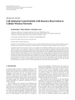
In Figure 10, the envelope of the B-IFDMA transmit
signal is investigated in terms of the well-known Peak-to-
Average Power Ratio (PAPR) [39]forN
= 1024 subcarriers
in the system and Q
= 64 subcarriers assigned to a user using
QPSK modulation. As references, the PAPR of two signals
are given that differ from the B-IFDMA in the following
properties. The first signal does not use DFT precoding
and the second signal uses a random allocation of the
subcarrier blocks instead of a regular one. From Figure 10
it can be clearly seen that both DFT precoding and regular
allocation of the subcarrier blocks is required in order to
provide a low PAPR. B-IFDMA provides a mean PAPR that is
10 EURASIP Journal on Wireless Communications and Networking
Table 2: Overall performance comparison of SISO B-IFDMA with Q = 32 or Q = 64 subcarriers per user and M = 4orM = 8 subcarriers
per block with N
= 1024 subcarriers in the system.
Gain N
t
= 3 N
t
= 6
(dB) Kalman Block-LSE Kalman Block-LSE
B-IFDMA Q = 32, M = 4versusM = 8(L = 8versusL = 4)
Diversity, BER 10
−3
1.91.91.91.9
Channel est. 11 dB
−0.5 −0.8 −0.4 −0.5
To t a l 1 .41.11.51.4
B-IFDMA Q = 64, M = 4versusM = 8(L = 16 versus L = 8)
Diversity, BER 10
−3
0.70.70.70.7
Channel est. 10 dB
−0.5 −0.8 −0.4 −0.5
To t a l 0 .2 −0.10.30.2
1.2–1.5 dB lower than the mean PAPR of the corresponding
scheme without DFT precoding. Compared to a scheme
with random allocation of the subcarrier blocks with DFT
precoding, the PAPR gain of B-IFDMA is greater than 3 dB
for a number L
= 64 subcarrier blocks, that is, for the special
case of IFDMA. The gain decreases to
≈0.7 dB for L = 4
subcarrier blocks. For L
= 2, the regular and the random
allocation of the subcarrier blocks are equivalent except for
the distance of the subcarrier blocks and, thus, the mean
PAPR is similar.
Figure 11 analyzes the envelope of the B-IFDMA transmit
signal based on different metrics. In addition to the PAPR,
the well-known Raw Cubic Metric (RCM) as defined in [40,
equation (15)], which is related to the 3GPP Cubic Metric
(CM) in [41], is regarded. The motivation for the CM and
RCM are the fact that the primary cause of distortion is the
third order nonlinearity of the amplifier gain characteristic.
Moreover, the HPA power efficiency is predicted. For that
purpose, a nonlinear amplifier is assumed that produces
increased out-of-band radiation due to nonlinear distortions
dependent on the envelope of the input signal. The power
efficiency of the given HPA depends on the power back-
off (BO) that is required to meet a given spectral mask for
the transmit signal. Thus, for investigation of the impact of
the envelope fluctuations on the power efficiency, also the
required BO is analyzed. In the following, for the HPA, the
well-known Rapp model [39] with Rapp-parameter p
= 2is
used which represents the model of a power amplifier with
high nonlinearities. The spectrum requirement mask is rep-
resentative for IMT Advanced systems, and is given in [38].
The results for the different metrics are summarized
in Figure 11. Again, N
= 1024 subcarriers is assumed in
the system, with Q
= 64 subcarriers per user and QPSK
modulation. A scheme without DFT precoding is regarded
as a reference. It can be concluded that, regardless of the
number L of subcarrier blocks, for B-IFDMA, the envelope
fluctuations are significantly lower compared to the scheme
without DFT precoding. The mean PAPR and the RCM have
a minimum for L
= Q and L = 1, that is, for LFDMA and
for IFDMA, where B-IFDMA can be interpreted as a single-
carrier scheme and have a maximum for L
= 8. However,
0
1
2
3
4
5
6
7
8
9
10
Mean PAPR (dB)
1 2 4 8 16 32 64
L
Random block allocation
B-IFDMA
No DFT pre-coding
Figure 10: Mean PAPR of B-IFDMA transmit signals with Q =
64 as a function of number of blocks L compared to the
corresponding schemes without DFT precoding and schemes with
random allocation of the subcarrier blocks.
even at the maximum, the envelope fluctuations of B-IFDMA
are considerably lower than for a corresponding scheme
without DFT precoding. In difference to the mean PAPR and
the RCM, the required BO increases with decreasing number
L of subcarrier blocks. The reason for that is that in addition
to the envelope of the signal also the shape of the spectrum
changes and the side-lobes are increased. However, for the
specialcaseofL
= 1, that is, for LFDMA, the side-lobes are
significantly reduced. Thus, in this case, the spectral mask is
less relevant, and results for L
= 1 are omitted.
From Figure 11 it can be concluded that the effects shown
in Figure 10 can be considered to be almost independent of
the metric that is used. Thus, B-IFDMA can be considered
to provide a higher power efficiency and lower envelope
fluctuations compared to schemes without DFT precoding
and without regular subcarrier allocation, respectively.
EURASIP Journal on Wireless Communications and Networking 11
0
5
10
15
RCM, mean PAPR and required BO (dB)
1 2 4 8 16 32 64
L
RCM, B-IFDMA
Mean PAPR, B-IFDMA
Required BO, B-IFDMA
RCM, no DFT
Mean PAPR, no DFT
Required BO, no DFT
Figure 11: Results for the analysis of the envelope fluctuations of
B-IFDMA transmit signals with Q
= 64 (with DFT) compared
to signals without DFT precoding for different numbers L of
subcarriers per block using different metrics.
0
10
20
30
40
50
60
Overall efficiency (%)
15 20 25 30 35 40
P
out
(dBm)
V
DC
= 22 V
V
DC
= 17 V
V
DC
= 11 V
V
DC
= 8V
V
DC
= 6V
Figure 12: Illustration of overall efficiency as a function of output
power for different amplifier drive voltages V
DC
using the HPA in
[42], where V
DC
= 22 V is the highest possible drive voltage.
4.2. Gain with Time Localized Transmission. In Section 4.1,
we characterized the envelope properties of B-IFDMA
according to different metrics. In this section we make an
analysis of the energy efficiency of B-IFDMA with a real
amplifier. The aim of this investigation is to correlate the
HPA energy efficiency with the prediction by the metrics in
Section 4.1. The aim is also to show and quantify the gain
by optimizing the operation point of the power amplifier,
in order to motivate the benefit of the TDMA component
within the B-IFDMA scheme.
4.2.1. HPA Efficiency. The efficiency of an HPA is best
described by the overall efficiency,definedas
η
A
=
P
Out
P
DC
+ P
In
,
(13)
where P
In
is the power at the input of the HPA, and P
Out
is
the resulting output power. P
DC
is the power at the DC input
of the amplifier, computed as the product between the DC
voltage and the DC current, P
DC
= V
DC
· I
DC
.Foragiven
V
DC
, the efficiency is a function mainly of the desired output
power; the general trend is that the efficiency is higher for
high output powers. However, by varying the drive voltage
V
DC
, the efficiency curve of the amplifier can be changed.
In Figure 12, we illustrate the overall efficiency as a function
of output power for different drive voltages V
DC
, when the
input signal is an unmodulated carrier signal, using the HPA
in [42].
Figure 12 shows that the efficiency of the amplifier is
highest when its output power is close to the maximum
attainable output power, that is, when it is driven close to
saturation. However, due to the signal dynamics and other
system considerations such as power control, it is in general
not possible to drive the amplifier in its most efficient mode
at all times. In situations when we need a lower average
output power, we can see that by lowering the (constant)
drive voltage we can get an improved efficiency, but the
overall efficiency is still lower than when its output power
is close to the maximum attainable output power. (The
optimal way of driving the amplifier would be to jointly vary
the drive and Radio Frequency (RF) power for maximum
efficiency [42],butthisisnotgenerallyregardedaspractical
to implement today.)
We have evaluated the overall efficiency of several
different amplifiers, when driven at different constant V
DC
and with different modulated signals. The constant V
DC
drive
voltage has been chosen for maximum overall efficiency,
and the following modulated input signals have been used:
OFDM, IFDMA, LFDMA and B-IFDMA with different
numbers of blocks (L) and pulse shaped as in Section 4.1.
To compute the overall efficiency of the HPA, we use the
measured characteristics of the HPA in terms of required P
DC
for a given P
In
and desired P
Out
of each signal sample, and
then we perform a weighted averaging over the consumed
and transmitted powers using the desired output power
histograms for the modulated signal. Thus, ideal predistor-
tion of the signals is assumed, and the operation point is
chosen such that maximum 1% of the samples are above the
saturation point, which is generally regarded as an acceptable
level of signal distortion.The results are shown in Tab le 3 .
12 EURASIP Journal on Wireless Communications and Networking
As can be seen, we have the following.
(i) Due to the different amplitude distributions of these
signals, they lead to different power efficiencies.
(ii) In accordance with the envelope metric results in
Section 4.1, and compared to the TDMA-OFDM
system, the various DFT-precoding based schemes
perform better both with respect to the overall
efficiency and with respect to the maximum output
power (not shown in Ta bl e 3). This can potentially
be used for increasing the cell size and/or larger data
rates at a given path loss, provided regulations on
maximum transmit power are not violated. The bet-
ter HPA efficiency also implies less heat dissipation in
the UE, which simplifies the design and can cut other
supporting component costs.
(iii) The difference in efficiency of the various DFT
precoded schemes is very small, including the B-
IFDMA scheme. In particular, these differences are
smaller than predicted by the envelope metric results
in Section 4.1.
The results in Ta bl e 3 were obtained using the class E
Laterally Diffused Metal Oxide Semiconductor (LDMOS)
amplifier in [42]. However, to verify the qualitative conclu-
sions we have also repeated the experiments with a class D
LDMOS and a class E Gallium Nitride (GaN) amplifier. We
have also studied other designs in the literature, for example,
[43], and other classes of operation, such as class A, AB, or B.
The overall conclusion is that the qualitative results are the
same as above regardless of the amplifier.
4.2.2. Efficient HPA Operation. From the results in Tabl e 3 we
see that there is a gain to be made if the power amplifier as
often as possible can operate close to its optimal operation
point. However, in order to limit the Multiple Access
Interference (MAI) from different users in a multicarrier
based uplink due to imperfections in transmitter hardware,
synchronization and Doppler spread, it is important to have
some kind of power control to limit the difference in received
power spectral density from different users. Thus, if all
users were allocated the same number of subcarriers, with
a constraint on maximum received power spectral density,
there would be situations when the HPA has to operate at a
low and suboptimal transmit power level. In these scenarios
HPA efficiency would benefit from an increase in the number
of allocated subcarriers in a given OFDM symbol, because
then the UE could transmit during a shorter time, that is,
on a lower number of OFDM symbols, for a given average
data rate. One possibility to do this would be to decrease the
subcarrier separation in an IFDMA scheme, but that would
imply a larger channel estimation overhead due to the low
correlation among the subcarriers as shown in Section 3.2.
With a short frame duration, aiming at low delays, this
overhead would be prohibitive. In addition, it would limit
the possibility for coexistence with adaptive TDMA/OFDMA
as discussed in [9].
In order to quantify the HPA efficiency with and without
time localized transmission, we assume that the choices are to
either (a) transmit at full power 25% of the time, and turn off
the transmitter for 75% of the time, or (b) to transmit at 25%
of full power all the time. Thus, in scenario (b) the amplifier
is backed-off 6 dB compared to scenario (a). In a BS, the
amplifier is usually optimized for a high output power, while
in the UEs the amplifier works at a low power level most of
the time, for example, 21–46 dBm for BSs and 21–24 dBm
for UEs depending on the deployment scenario ranging from
localareatowidearea,[19].
As seen in Tab le 3 maximum overall efficiency is obtained
when operating the HPA close to the maximum output
powerlevel.Thusscenario(a)leadstohigherefficiency
in all cases. For example, assume the same number of
well separated blocks L. If the options are to use IFDMA
in the full duration of a chunk with 32 subcarriers at a
constant output power level of 18 dBm, we get an overall
HPA efficiency of 29% (Tab le 3
row 2, column 5), whereas
if we use B-IFDMA with Q
= 128 subcarriers and M = 4
subcarriers per block (i.e., L
= 32 blocks) one quarter of
the frame duration and an instantaneous output power level
of 24 dBm, we get an overall HPA efficiency of 41% (Tab le 3
row 5, column 4). The corresponding difference is smaller
when the average transmit power is closer to the maximum
efficiency. For example, at 24 dBm average transmit power
the corresponding overall efficiencies are 43% (Ta bl e 3 row
2, column 4) for IFDMA and 45% (Tabl e 3 row 5, column
3) for B-IFDMA. Thus, there is a large benefit to introduce
a TDMA component in the B-IFDMA scheme in order to
allow a shorter transmit duration than a full frame with a
larger instantaneous data rate, except in case the required
overall data rate is already close to the maximum supported.
With time-localized transmission and reception, we also
introduce the additional possibility of micro-sleep mode
within scheduled frames. The feasibility and potential of
micro-sleep mode is discussed in [12].
4.3. End-to-End Energy Efficiency. By combining the results
in Sections 4.1 and 4.2 with the results in Section 3,wecan
quantify the end-to-end energy efficiency for different B-
IFDMA parameterizations. Below we illustrate this tradeoff,
by building on the examples in Section 3.3,assumingatarget
BERof10
−3
.
Example 3 (revisited). Similar to the mean PAPR results for
Q
= 64 subcarriers in Figure 10, the mean PAPR for B-
IFDMA with Q
= 32 subcarriers is very similar for M = 4
(L
= 8) and M = 8(L = 4). In addition, not shown in this
paper, the mean PAPR values of B-IFDMA have been found
to correlate well with the overall HPA efficiency values. Thus,
with SISO using Q
= 32 subcarriers, the scheme with L = 8
blocks with M
= 4 subcarriers each seems to provide the best
tradeoff also considering end-to-end energy efficiency.
Example 4 (revisited). The HPA efficiency for Q
= 64
predicted by the mean PAPR as shown in Figure 10 is very
similar also for L
= 16 blocks compared to L = 8. Thus, also
with respect to end-to-end energy efficiency the two cases
with M
= 4andM = 8 subcarriers per block seem to per-
form very similar. If instead the HPA efficiency is predicted
EURASIP Journal on Wireless Communications and Networking 13
Table 3: Overall efficiency η
A
in % of the HPA in [42] with constant drive voltage operation with V
DC
chosen for maximum overall efficiency
for different input signals, all using QPSK symbol constellations and a system with N
= 1024 subcarriers.
Const V
DC
Max efficiency Max efficiency −6dB 30dBm 24dBm 18dBm
TDMA- 40% @ 34% @ 39% @ 39% @ 29% @
OFDM 26 dBm 20 dBm 30 dBm 24 dBm 18 dBm
IFDMA 49% @ 43% @ 49% @ 43% @ 29% @
Q
= 32 30 dBm 24 dBm 30 dBm 24 dBm 18 dBm
B-IFDMA 47% @ 38% @ 45% @ 41% @ 29% @
Q, M
= 32, 4 28 dBm 22 dBm 30 dBm 24 dBm 18 dBm
B-IFDMA 46% @ 38% @ 45% @ 41% @ 29% @
Q, M
= 64, 4 28 dBm 22 dBm 30 dBm 24 dBm 18 dBm
B-IFDMA 46% @ 38% @ 45% @ 41% @ 29% @
Q, M
= 128, 4 28 dBm 22 dBm 30 dBm 24 dBm 18 dBm
LFDMA 48% @ 38% @ 47% @ 42% @ 29% @
Q
= 32 28 dBm 22 dBm 30 dBm 24 dBm 18 dBm
by the required power backoff to satisfy a spectrum mask,
the results for required BO in Figure 11 apply. In this case,
the end-to-end energy efficiency seems to be around 0.5dB
better with L
= 16, that is, for M = 4 subcarriers per block.
In the next example, we now make a comparison between
B-IFDMA and IFDMA with the same data rate, also taking
the end-to-end energy efficiency into account.
Example 5. Let us compare the two options to use IFDMA
in SISO at the same data rate, for example, B-IFDMA using
M
= 1, L = 32, and N
t
= 12 having Q = 32 subcarriers
for the user with B-IFDMA using M
= 4, L = 32, and
N
t
= 3 having Q = 128 subcarriers. The data rate is
the same since in both cases M
· N
t
· L = 384 symbols
are transmitted per slot. To generate the same RF energy,
IFDMA would operate with 6 dB less transmit power during
4 times longer duty cycle. Thus, this scenario is especially
relevant for the case when the required uplink data rate
is below the maximum achievable for the UE at the given
channel conditions. Consider the diversity gains in Figure 6,
the channel estimation performance in Figure 8 and the HPA
efficiency for this case in Ta ble 3 . Using the corresponding
HPA efficiency values as discussed in Section 4.2.2, the end-
to-end energy efficiency comparison is shown in Tab le 4 for
target BER 10
−3
.AsseeninTa ble 4 , there is an overall gain
for B-IFDMA with M
= 4 over the IFDMA case. The gain
is more than 2 dB at low output power levels, but there is
a substantial gain also at operation closer to the maximum
output power level. This gain is achieved without considering
additional potential sleep mode gains enabled by the short
blocks, as mentioned in Section 4.2.2.
5. Robustness
In this section, the robustness of B-IFDMA to carrier
frequency offsets (CFOs) and to Doppler spreads (DSs) is
analyzed for the uplink dependent on the signal parameters.
The aim of this investigation is to show that the block based
Table 4: End-to-end energy efficiency comparison of SISO B-
IFDMA using block size M
= 4, N
t
= 3andQ = 128 subcarriers
peruserattwodifferentHPAoutputpowerlevelsversusB-IFDMA
using block size M
= 1, N
t
= 12 and Q = 32 subcarriers per user at
−6 dBm lower HPA output power level. IFDMA uses 4 times longer
blocks. L
= 32 in both cases and there are N = 1024 subcarriers in
the system.
Gain 30 dBm 24 dBm
(dB) Kalman Block-LSE Kalman Block-LSE
B-IFDMA M =4, N
t
=3, Q =128 versus M =1, N
t
=12, Q =32
Diversity, BER 10
−3
0.24 0.24 0.24 0.24
Channel est. 9 dB
−0.15 0.1 −0.15 0.1
HPA efficiency 0.20.22.07 2.07
To t a l 0 .29 0.54 2.16 2.41
subcarrier allocation in B-IFDMA enables the possibility to
combine robustness and provision of frequency diversity.
In mobile radio applications, CFOs are typically caused
by oscillator imperfections due to low cost hardware com-
ponents or Doppler shifts due to the mobility of the users.
The CFOs result in a shift of the spectra of the different
users’ signals. Hence, the orthogonality of the subcarriers is
destroyed and inter-carrier interference (ICI) occurs.
In general, two types of ICI can be distinguished. Re-
garding a particular user’s signal, on the one hand, due to the
shift of the spectrum, interference between the subcarriers
of this user occurs. In the following this is denoted as self-
interference (SI). On the other hand, in addition interference
between the subcarriers of different users occurs. This case
is in the following denoted as multiple access interference
(MAI).
The DS is caused by the fact that in a mobile radio
channel typically the same signal is received from different
propagation paths where each path suffers from a different
Doppler shift. The superposition of differently shifted repli-
cas of the same signal at the receiver leads to a spread of the
subcarriers of the different users’ signals. Consequently, also
for DSs the orthogonality of the subcarriers is destroyed and
14 EURASIP Journal on Wireless Communications and Networking
10
−4
10
−3
10
−2
10
−1
BER
0246810
E
s
/N
0
M = 1
M
= 2
M
= 4
M
= 8
M
= 16
M
= 32
M
= 64
Δ f
= 0
Figure 13: Performance for Δ f
(k)
CFO
= 10% maximum relative CFO
for different numbers M of subcarriers per block, assuming N
=
1024 subcarriers and Q = 64 subcarriers per user.
10
−4
10
−3
10
−2
10
−1
BER
0246810
E
s
/N
0
M = 1
M
= 2
M
= 4
M
= 8
M
= 16
M
= 64
Δ f
= 0
Figure 14: Performance for Doppler Spread with Δ f
(k)
CFO
= 15%
relative carrier frequency offset per path for different numbers M of
subcarriers per block, assuming N
= 1024 subcarriers and Q = 64
subcarriers per user.
ICI occurs. Similar to the effects of CFOs, also for DSs two
types of ICI, namely SI and MAI can be distinguished.
For uplink transmission, the CFOs and the DS for the
received signals of different users are different. Thus, if CFOs
and DS are known at the receiver, compensation of SI is
possible, whereas compensation of MAI can only be obtained
by application of joint detection techniques that require a
high computational effort.
For the analysis of the robustness of B-IFDMA to CFOs,
let
Δ
f
(k)
CFO
=
Δ f
(k)
CFO
Δ f
(14)
denote the relative CFO of user k normalizing the CFO Δ f
(k)
CFO
of user k to the subcarrier bandwidth Δ f . The relative CFO
f
(k)
CFO
is modeled as a random variable that is uniformly dis-
tributed in [
−Δ f
(k)
CFO,max
, Δ f
(k)
CFO,max
]withΔ f
(k)
CFO,max
denot-
ing the maximum relative CFO of user k that occurs. The
CFOs f
(k)
CFO
are assumed to be known at the receiver. Thus,
SI can be perfectly compensated by reversing the CFO f
(k)
CFO
.
For the compensation of the MAI, joint detection techniques
are required. For this investigation, it is assumed that, due
to the high complexity, the compensation of MAI at the
receiver is not feasible. In order to analyze the robustness
to CFOs independently of the diversity effects, a B-IFDMA
transmission over an AWGN channel is regarded.
For the analysis of the robustness of B-IFDMA to DSs, let
Δ
f
(k)
DS
=
Δ f
(k)
DS
Δ f
(15)
denote the relative DS of user k normalizing the DS Δ f
(k)
DS
of user k to the subcarrier bandwidth Δ f . Similar to the
modelling of the CFOs, also the DS Δ
f
(k)
DS
is modelled as
a random variable. Assuming that for the different prop-
agation paths the angle of arrival is uniformly distributed
in [0, 2π], the relative Doppler shift is Jakes distributed in
[
−Δ f
(k)
D,max
, Δ f
(k)
D,max
], where Δ f
(k)
D,max
denotes the maximum
Doppler shift normalized to the subcarrier bandwidth Δ f .
At the receiver, SI is combatted by application of a linear
Minimum Mean Square Error (MMSE) receiver, cf. [44].
For the compensation of the MAI, again, joint detection
techniques are required and it is assumed that, due to
the high complexity, the compensation of MAI at the
receiver is not feasible. In order to separate the effect of the
Doppler spread from frequency selective fading effects that
are also caused by multipath propagation, a Doppler spread
channel according to [44] is regarded, that is, the different
propagation paths are assumed to arrive at the receiver at
the same time. The channel is distorted by AWGN and the
received signals from the different propagation paths suffer
from mutually independent relative Doppler shifts.
Figure 13 depicts the performance results without coding
for the robustness investigations to CFOs assuming N
=
1024 subcarriers in the system, Q = 64 subcarriers per user,
K
= 16 users and Δ f
(k)
CFO
= 10% for all users. From Figure 13
it can be concluded that, for B-IFDMA, the robustness to
CFOs increases with an increasing number M of subcarriers
per block. The reason for that is that the strongest inter-
carrier interference is caused by neighboring subcarriers.
Thus, increasing the number of neighboring subcarriers
belonging to the same user increases the robustness to
MAI at the expense of additional SI that, however, can be
compensated. Note, that already for low numbers M of
EURASIP Journal on Wireless Communications and Networking 15
subcarriers per block the robustness of B-IFDMA to CFOs is
significantly improved.
Figure 14 depicts the performance results for the robust-
ness investigations to DS assuming the same parameters as
in Figure 13 and Δ
f
(k)
D,max
= 15% for all users. The value for
Δ
f
(k)
D,max
represents the maximum relative Doppler shift for a
system with Δ f
= 10 kHz and a carrier frequency of 5 GHz
with a user velocity of 315 km/h and, thus, represents a high
mobility scenario, for example, for high speed trains.
From the results in Figure 14 it can be concluded that
also the robustness of B-IFDMA to DS increases with an
increasing number M of subcarriers per block. The reason
is the same as for the improved robustness to CFOs. Again,
already for small numbers M a significant robustness gain is
provided. The increased robustness to CFOs and DSs of B-
IFDMA with M>1 makes B-IFDMA suitable for high speed
users and systems with limited frequency synchronization.
6. Discussion of Results
In this section we summarize and comment on the investiga-
tionsmadeinSections3, 4,and5.InSection 1, we identified
the following important requirements for the diversity based
multiple access scheme, which should complement the FA
multiple access scheme in an IMT Advanced capable system.
Below we comment on the suitability of B-IFDMA to meet
these requirements.
(i) Robustness to small-scale fading without time diversity.
The results in Section 3 showed that B-IFDMA can be
defined based on a rather few number of subcarriers
per block also with realistic channel estimation
performance. Thus, also at rather low data rates, that
is, rather few subcarriers assigned to a user per slot, a
large frequency diversity can be obtained.
(ii) Tuneable degree of frequency-diversity. As shown in
Sections 3.3 and 4.3 rather small blocks, also with
a sub-slot duration, can provide a good error rate
performance. Thus, for a given data rate additional
blocks can be allocated either well-separated in
frequency to provide additional frequency-diversity,
or adjacent in time or frequency (i.e., in same chunk
cf. Figure 1), if enough diversity is already obtained
from the frequency and/or spatial domain.
(iii) Need to support high e nergy efficiency in the transmit-
ters and the receivers. We showed in Section 4 that B-
IFDMA including pulse shaping can provide similar
HPA efficiency as IFDMA and LFDMA, which is
substantially better than for TDMA-OFDM without
DFT precoding. In addition, whenever the UE is not
power limited, in Section 4.3 a substantial overall
gain of more than 2 dB is shown with time localized
transmission in a fraction of the time slot, also when
including realistic channel estimation performance
and disregarding potential sleep mode gains. (These
results are valid also for a downlink scenario using the
B-EFDMA scheme.)
(iv) Robustness to carrier frequency offsets and large
Doppler spread. This property was evaluated in
Section 5 and the conclusion is that already for small
numbers of subcarriers per block a significant robust-
ness gain against carrier CFOs as well as against
Doppler spreads is provided compared to IFDMA.
This property could provide a significant gain in
certain scenarios, like for deployment in frequency
bands using a several GHz carrier frequency. Another
scenario is to support high-speed trains, and/or
to deploy a system with rather narrow subcarrier
bandwidth.
(v) Support for widely varying packet sizes. Due to the
good error rate performance of B-IFMDA with few
number of subcarriers, transmission of rather small
blocks perform well by using the TDMA component.
Large packets can use the full chunk duration.
The benefit of configuration flexibility motivates the
introduction of a small basic block consisting of, for
example, M
= 4 × N
t
= 3 (subcarriers × OFDM
symbols) in B-IFDMA as a building block to enable
adaptiveblockallocationindifferent deployment and
usage scenarios, as illustrated in Figure 1,see[5, 45]
for further discussion.
(vi) Enable efficient resource allocation. As discussed in
[45]justafewdifferent block allocations should be
sufficient in a cell. The regular block allocation is
beneficial for low addressing overhead, and it was
shown in Section 4.1 to also be beneficial for lowering
the envelope variations.
(vii) Beofuseforin-bandcontrolsignals. This is possi-
ble due to the efficient support for small packets
as discussed above. In addition, the short TDMA
component in B-IFDMA is useful to support precise
timing of control messages for FA transmission, cf.
[9].
(viii) Enable efficient coexistence with adaptive TDMA/
OFDMA. Since B-IFDMA also is based on OFDM
with the same parameters, these two schemes
are compatible. With well-separated regular block
allocations in frequency, adaptive TDMA/OFDMA
resources can be interlaced as shown, for example, in
[9, Figure 2].
(ix) Facilitate low complexity transmitter in UEs.Thegood
envelope properties of B-IFDMA enables the use of
a less complex HPA and predistortion unit. In the
appendix we show that a B-IFDMA signal can be
efficiently generated in the time domain, that is,
without the DFT operation.
7. Conclusions
In this paper we have shown that B-IFDMA, which is
a generalization of the SC-FDMA concept, is a power
efficient, flexible and scalable multiple access scheme that
can serve as a robust complement to future adaptive IMT
Advanced capable wireless systems. Based on the included
16 EURASIP Journal on Wireless Communications and Networking
investigations, we have shown that B-IFDMA is able to
provide equal or better error rate performance than IFDMA
and LFDMA, when considering realistic channel estimation
performance at the receiver and no reliable channel state
information at the transmitter, also for rather low data rates,
and without using time diversity.
We also showed that B-IFDMA provides better amplifier
efficiency than OFDMA and can provide better end-to-
end energy efficiency than IFDMA and LFDMA. These
investigations motivated the use of the DFT precoding step,
and the integration of the TDMA component within the B-
IFDMA scheme. These results also motivated the use of a
regular subcarrier allocation in B-IFDMA.
Then, we showed that B-IFDMA offers the possibility
to combine robustness against carrier frequency offsets and
Doppler spread with provision of frequency diversity. This
property could provide a significant gain in certain scenarios,
like for deployment in frequency bands using a several
GHzcarrierfrequency.Anotherscenarioistosupporthigh-
speed trains, and/or to deploy a system with rather narrow
subcarrier bandwidth.
Finally, we argued for that B-IFDMA has the capability to
fulfill and provide a good tradeoff between the requirements
envisioned for the robust transmission mode in the uplink of
future IMT Advanced capable wireless systems.
Appendix
Time Domain Representation
In this appendix, the samples of the B-IFDMA time domain
signal are analyzed. For sake of simplicity, throughout this
appendix, the index η is omitted. Combining the precoding,
the user specific block-interleaved subcarrier mapping and
the OFDM modulation, the elements x
(k)
n
, n = 0, , N − 1,
of the modulated data vector x
(k)
in (6)canbewrittenas
x
(k)
n
=
M−1
μ=0
d
(k)
(n+μL)modQ
·Θ
(μ,k)
n
(A.1)
with
Θ
(μ,k)
n
=
L
QN
e
j(2π/N)nkM
M
−1
m=0
e
−j2πm(n/Q−n/N+μ/M)
(A.2)
for μ
= 0, , M − 1. The derivation can be found in [46].
Equation (A.1)isillustratedinFigure 15.
The sequence d
(k)
(n+μL)modQ
in (A.1) can be interpreted as
a compression of the sequence of data symbols d
(k)
q
, q =
0, , Q − 1, in time by factor N/Q,asubsequentN/Q-fold
repetition and, finally, a cyclic shift of the N elements of the
resulting sequence by n + μL,asillustratedin[46, Figure 3].
Thus, B-IFDMA can be considered as a superposition of M
single carrier signals weighted by different complex numbers
Θ
(μ,k)
n
.
d
(k)
q
Compression
and repetition
by N/Q
s
(k)
n
Cyclic shift
by L
Cyclic shift
by (M
−1)L
.
.
.
Θ
(0,k)
n
Θ
(1,k)
n
Θ
(M−1,k)
n
x
(k)
n
+
Figure 15: B-IFDMA time domain modulation.
The expression e
j(2π/N)kM
in (A.2)representsauser
specific frequency shift by kM.ForM
= 1 the expression
Θ
(μ,k)
n
reduces to
Θ
(μ,k)
n
=
Q
N
e
j(2π/N)kn
,
(A.3)
and (A.1) simplifies to compression and repetition of the
data symbols, subsequent user specific frequency shift and a
normalization to
Q/N. This is equivalent to the generation
of an IFDMA signal [14] which is a single carrier signal, that
is, a serially modulated carrier. Note that also for the special
case M
= Q, an expression is obtained that is equivalent to a
single carrier signal because for this case the expression from
(A.1) is equivalent to the time domain samples of an LFDMA
signal that are described in [47].
Since the coefficients by (A.2) are independent from the
data symbols, they can be calculated offline. Thus, (A.1)
also represents an alternative implementation for B-IFDMA
modulation that does not require N and Q to be powers of 2
as it would be the case for an implementation of B-IFDMA
modulation according to (6), if the Fast Fourier Transform
(FFT) algorithm is used.
Similar to the modulation, also the B-IFDMA demod-
ulation can be reformulated as follows. The elements ρ
(k)
q
,
q
= 0, , Q − 1 of the demodulated B-IFDMA signal
ρ
(k)
= F
H
Q
·
M
(k)
BI
†
·F
N
·r
(A.4)
can be expressed as
ρ
(k)
q
=
N/L−1
ν=0
r
(q+νL)modN
·Ψ
(ν,k)
(q+νL)modN
(A.5)
with
Ψ
(ν,k)
n
=
Θ
(−ν mod M,k)
n
∗
; n =
q + νL
mod N.
(A.6)
The derivation of the demodulator can be found in [46]
with an illustration in [46, Figure 4]. It can be regarded as
a generalization of the demodulation for IFDMA described
in [14].
EURASIP Journal on Wireless Communications and Networking 17
Acknowledgments
This work has partly been performed in the framework
of the IST project IST-4-027756 WINNER II, which was
partly funded by the European Union. The authors would
like to acknowledge the contributions of their colleagues in
WINNER II, although the views expressed are those of the
authors and do not necessarily represent the project.
References
[1] International Telecommunication Union Radiocommunica-
tion Sector ITU-R, “Recommendation ITU-R M1645, frame-
work and overall objectives of the future development of IMT-
2000 and systems beyond IMT-2000,” 2003.
[2]C.Wijing,K.Doppler,K.Kallioj
¨
arvi, et al., “WINNER
II system concept: advanced radio technologies for future
wireless systems,” in Proceedings of the ICT-Mobile Summit
Conference, June 2008.
[3] S. Parkvall, E. Dahlman, A. Furusk
¨
ar, et al., “LTE-advanced
evolving LTE towards IMT-advanced,” in Proceedings of the
68th IEEE Vehicular Technology Conference (VTC ’08), pp. 1–5,
Calgary, Canada, September 2008.
[4] G. Auer, M. D
¨
ottling, K. Doppler, et al., “D6.13.14 WINNER
II system concept description,” Tech. Rep. IST-4-027756
WINNER II, version 1.1, WINNER, January 2008.
[5] M. D
¨
ottling, W. Mohr, and A. Osseiran, Radio Technologies
and Concepts for IMT-Advanced, John Wiley & Sons, New
York, NY, USA, 2009.
[6] A. Tyrrell and G. Auer, “Imposing a reference timing onto
firefly synchronization in wireless networks,” in Proceedings of
the 65th IEEE Vehicular Technology Conference ( VTC ’07),pp.
222–226, Dublin, Ireland, April 2007.
[7] D. Falconer, B. Ng, C T. Lam, et al., “D2.3.3 WINNER II link
level procedures for the WINNER system,” Tech. Rep. IST-4-
027756 WINNER II, version 1.00, WINNER, November 2007.
[8] M. D
¨
ottling,M.Sternad,G.Klang,J.vonH
¨
afen, and M.
Olsson, “Integration of spatial processing in the WINNER
B3G air interface design,” in Proceedings of the 63rd IEEE
Vehicular Technology Conference (VTC ’06), vol. 1, pp. 246–
250, Melbourne, Australia, May 2006.
[9] M.Sternad,T.Svensson,T.Ottosson,A.Ahl
´
en,A.Svensson,
and A. Brunstrom, “Towards systems beyond 3G based on
adaptive OFDMA transmission,” Proceedings of the IEEE, vol.
95, no. 12, pp. 2432–2455, 2007.
[10] M. Sternad, S. Falahati, T. Svensson, and D. Aronsson, “Adap-
tive TDMA/OFDMA for wide-area coverage and vehicular
velocities,” in Proceedings of the IST Mobile and Vehicular
Communication Summit, Dresden, Germany, June 2005.
[11] K. Safjan, J. Oszmianski, M. D
¨
ottling, and A. Bohdanowicz,
“Frequency-domain link adaptation for wideband OFDMA
systems,” in Proceedings of the IEEE Wireless Communications
and Networking Conference (WCNC ’08), pp. 1703–1708, Las
Vegas, Nev, USA, April 2008.
[12] T. Svensson, T. Franky, D. Falconer, et al., “B-IFDMA—a
power efficient multiple access scheme for non-frequency-
adaptive transmission,” in Proceedings of the 16th IST Mobile
and Wireless Communications Summit, Budapest, Hungary,
July 2007.
[13] D.Galda,H.Rohling,E.Costa,H.Haas,andE.Schulz,“Alow
complexity transmitter structure for OFDM-FDMA uplink
systems,” in Proceedings of the IEEE Vehicular Technology
Conference (VTC ’02), vol. 4, pp. 1737–1741, Birmingham,
UK, May 2002.
[14] U. Sorger, I. De Broeck, and M. Schnell, “IFDMA—a new
spreadspectrum multiple-access scheme,” in Multi-Carrier
Spread-Spectrum, pp. 111–118, Kluwer Academic Publishers,
Amsterdam, The Netherlands, 1997.
[15] E. Dahlman, S. Parkvall, J. Sk
¨
old, and P. Beming, 3G Evolution:
HSPA and LTE for Mobile Broadband, Academic Press, New
York, NY, USA, 2007.
[16] The 3rd Generation Partnership Project (3GPP), “Physical
layer aspects for evolved Universal Terrestrial Radio Access
(UTRA),” Technical Specification Group Radio Access Net-
work TR 25.814 v7.1.0, 3GPP, Sophia Antipolis Cedex, France,
2006.
[17] H. G. Myung, J. Lim, and D. J. Goodman, “Single carrier
FDMA for uplink wireless transmission,” IEEE Vehicular
Technology Magazine, vol. 1, no. 3, pp. 30–38, 2006.
[18] S. Plass, T. Svensson, and A. Dammann, “Block-equidistant
resource mapping in OFDM, MC-CDMA and SS-MC-MA,”
in Proceedings of the 12th International OFDM Workshop,
Hamburg, Germany, August 2007.
[19] M. D
¨
ottling, et al., “D6.13.7 WINNER II test scenarios and
calibration cases issue 2,” Tech. Rep. IST-4-027756 WINNER
II, version 1.00, WINNER, December 2006.
[20] T. Frank, A. Klein, E. Costa, and E. Schulz, “Interleaved
orthogonal frequency division multiple access with variable
data rates,” in Proceedings of the International OFDM Work-
shop, pp. 179–183, Hamburg, Germany, August-September
2005.
[21] T. Frank, A. Klein, and E. Costa, “IFDMA: a scheme com-
bining the advantages of OFDMA and CDMA,” IEEE Wireless
Communications, vol. 14, no. 3, pp. 9–17, 2007.
[22] Z. Wang and G. B. Giannakis, “Wireless multicarrier commu-
nications,” IEEE Signal Processing Magazine,vol.17,no.3,pp.
29–48, 2000.
[23] H. Sari, G. Karam, and I. Jeanclaude, “Frequency domain
equalization of mobile radio terrestrial broadcast channels,” in
Proceedings of the IEEE Global Telecommunications Conference
(GLOBECOM ’94), pp. 1–5, San Francisco, Calif, USA,
November-December 1994.
[24] D. Falconer, S. Ariyavisitakul, A. Benyamin-Seeyar, and B.
Eidson, “Frequency domain equalization for single-carrier
broadband wireless systems,” IEEE Communications Magazine,
vol. 40, pp. 58–66, 2002.
[25] S. M. Alamouti, “A simple transmit diversity technique for
wireless communications,” IEEE Journal on Selected Areas in
Communications, vol. 16, no. 8, pp. 1451–1458, 1998.
[26] H. Boelcskei and A. J. Paulraj, “Space-frequency coded
broadband OFDM systems,” in Proceedings of the IEEE Wireless
Communications and Networking Conference (WCNC ’00), vol.
1, pp. 1–6, Chicago, Ill, USA, September 2000.
[27] L. R. Bahl, J. Cocke, F. Jelinek, and J. Raviv, “Optimal decoding
of linear codes for minimizing symbol error rate,” IEEE
Transactions on Information Theory, vol. 20, no. 2, pp. 284–
287, 1974.
[28] P. Ky
¨
osti, J. Meinil
¨
a, L. Hentila, et al., “D1.1.2 WINNER II
channel models—part I channel models,” Tech. Rep. IST-4-
027756 WINNER II, version 1.2, WINNER, September 2007.
[29] G. Auer, “Analysis of pilot-symbol aided channel estimation
for OFDM systems with multiple transmit antennas,” in
18 EURASIP Journal on Wireless Communications and Networking
Proceedings of the IEEE International Conference on Commu-
nications (ICC ’04), vol. 6, pp. 3221–3225, Paris, France, June
2004.
[30] P. Hoeher, S. Kaiser, and P. Robertson, “Two-dimensional
pilot-symbol aided channel estimation by Wiener filtering,” in
Proceedings of the IEEE International Conference on Acoustics,
Speech, and Signal Processing (ICASSP ’97), vol. 3, pp. 1845–
1848, Munich, Germany, April 1997.
[31] O. Edfors, M. Sandell, J J. van de Beek, S. Wilson, and
P. B
¨
orjesson, “OFDM channel estimation by singular value
decomposition,” IEEE Transactions on Communications, vol.
46, no. 7, pp. 931–939, 1998.
[32] K. Fazel and S. Kaiser, Multi-Carrier Spread Spectrum Systems,
John Wiley & Sons, New York, NY, USA, 1st edition, 2003.
[33] C. T. Lam, D. Falconer, and F. Danilo-Lemoine, “Channel esti-
mation for sub-chunk-based DFT-precoded OFDM systems,”
in Proceedings of the 18th Meeting on Wireless World Research
Forum (WWRF ’07), Helsinki, Finland, June 2007.
[34] T. Kailath, A. H. Sayed, and B. Hassibi, Linear Estimation,
Prentice-Hall, Upper Saddle River, NJ, USA, 2000.
[35] D. Aronsson, Channel estimation and prediction from a
Bayesian perspective, Licentiate thesis, Department of Signals
and Systems, Uppsala University, Uppsala, Sweden, 2007.
[36] C.Wijting,K.Doppler,K.Kallioj
¨
arvi, et al., “Key technologies
for IMT-advanced mobile communication systems,” IEEE
Wireless Communications Magazine, 2009.
[37] D. Aronsson, T. Svensson, and M. Sternad, “Performance eval-
uation of memory-less and Kalman-based channel estimation
for OFDMA,” in Proceedings of the IEEE Vehicular Technology
Conference (VTC ’09), Barcelona, Spain, April 2009.
[38] T. Frank, A. Klein, and T. Haustein, “A survey on the envleope
fluctuations of DFT precoded OFDMA,” in Proceedings of
the International Conference on Communications (ICC ’08),
Beijing, China, May 2008.
[39]R.vanNeeandR.Prasad,OFDM for Wireless Multimedia
Communications, Artech House, Boston, Mass, USA, 1st
edition, 2000.
[40] A. Skrzypczak, P. Siohan, and J P. Javaudin, “Power spectral
density and cubic metric for the OFDM/OQAM modulation,”
in Proceedings of the 6th IEEE International Symposium on
Signal Processing and Information Technology (ISSPIT ’06),pp.
846–850, Vancouver, Canada, August 2006.
[41] The 3rd Generation Partnership Project (3GPP), “Compari-
son of PAR and cubic metric for powerderating,” Technical
Documents TDoc R4-040367, TSG RAN WG4 31, 3GPP,
Sophia Antipolis Cedex, France, 2004.
[42] H. M. Nemati, C. Fager, U. Gustavsson, et al., “Characteriza-
tion of switched-mode LDMOS and GaN power amplifiers for
optimal use in polar transmitter architectures,” in Proceedings
of the IEEE International Microwave Symposium, Atlanta, Ga,
USA, June 2008.
[43] F. Wang, D. Kimball, J. Popp, et al., “Wideband enve-
lope elimination and restoration power amplifier with high
efficiency wideband envelope amplifier for WLAN 802.11g
applications,” in Proceedings of the Microwave Symposium
Digest, pp. 645–648, La Jolla, Calif, USA, June 2005.
[44] T. H. Eggen, A. B. Baggeroer, and J. C. Preisig, “Communica-
tion over doppler spread channels-part I: channel and receiver
presentation,” IEEE Journal of Oceanic Engineering, vol. 25, no.
1, pp. 62–71, 2000.
[45] M. Sternad, T. Svensson, and M. D
¨
ottling, “Resource allo-
cation and control signaling in the WINNER flexible MAC
concept,” in Proceedings of the IEEE Vehicular Technology
Conference (VTC ’08), Calgary, Canada, September 2008.
[46] T. Frank, A. Klein, and E. Costa, “An efficient implementation
for block-IFDMA,” in
Proceedings of the IEEE International
Symposium on Personal, Indoor and Mobile Radio Communi-
cations (PIMRC ’07), Athens, Greece, September 2007.
[47] H. G. Myung, J. Lim, and D. J. Goodman, “Peak-to-average
power ratio of single carrier FDMA signals with pulse
shaping,” in Proceedings of the IEEE International Sympo-
sium on Personal, Indoor and Mobile Radio Communications
(PIMRC ’06), Helsinki, Finland, September 2006.