Báo cáo hóa học: "Research Article Dynamic Relaying in 3GPP " ppt
Bạn đang xem bản rút gọn của tài liệu. Xem và tải ngay bản đầy đủ của tài liệu tại đây (721.6 KB, 11 trang )
Hindawi Publishing Corporation
EURASIP Journal on Wireless Communications and Networking
Volume 2009, Article ID 731317, 11 pages
doi:10.1155/2009/731317
Research Article
Dynamic Relaying in 3GPP LTE-Advanced Networks
Oumer Teyeb,
1
Vinh Van Phan,
2
Ber nhard Raaf,
3
and Simone Redana
3
1
Radio Access Technologies (RATE) Section, Department of Electronic Systems, Aalborg University,
Niels Jernes Vej 12, 9220 Aalborg Øst, Denmark
2
Nokia Siemens Networks, COO Research Technology & Platform, Kaapelitie 4, 90630 Oulu, Finland
3
Nokia Siemens Networks, COO Research Technology & Platform, St Martin-Strasse 76,
81541 Munich, Germany
Correspondence should be addressed to Oumer Teyeb,
Received 30 January 2009; Accepted 30 July 2009
Recommended by Constantinos B. Papadias
Relaying is one of the proposed technologies for LTE-Advanced networks. In order to enable a flexible and reliable relaying support,
the currently adopted architectural structure of LTE networks has to be modified. In this paper, we extend the LTE architecture to
enable dynamic relaying, while maintaining backward compatibility with LTE Release 8 user equipments, and without limiting the
flexibility and reliability expected from relaying. With dynamic relaying, relays can be associated with base stations on a need basis
rather than in a fixed manner which is based only on initial radio planning. Proposals are also given on how to further improve
a relay enhanced LTE network by enabling multiple interfaces between the relay nodes and their controlling base stations, which
can possibly be based on technologies different from LTE, so that load balancing can be realized. This load balancing can be either
between differentbasestationsorevenbetweendifferent networks.
Copyright © 2009 Oumer Teyeb et al. This is an open access article distributed under the Creative Commons Attribution License,
which permits unrestricted use, distribution, and reproduction in any medium, provided the original work is properly cited.
1. Introduction
The use of radio relaying with the deployment of relay
nodes (RNs) for coverage extension in cellular networks
is not a new concept [1]. Apart from the main goal of
coverage extension, enabling relaying in a cellular network
can also help in the provisioning of high data rate coverage in
high shadowing environments (e.g., indoors) and hotspots,
reducing the deployment costs of cellular networks, pro-
longing the battery lifetime for user equipments (UEs), and
generally saving power by reducing the overall transmission
of cellular networks and enhancing cell capacity and effective
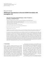
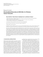
throughput. Figure 1 shows the most typical usage scenarios
for relaying.
Many of the earlier studies on relaying were rather
theoretical and mainly concerned with information theoretic
capacity limits. It is only recently that practical solutions
have been proposed due to the maturity of cellular systems
and the ever increasing demand for high data rate services
[1–4]. After being carefully considered in prestandardization
activities like the IST-WINNER project [2], relay enhanced
systems are achieving the level of maturity needed in ongoing
standardization activities. The best evidence of this maturity
is the IEEE 802.16j standard specifying relaying for the
mobile WiMAX (802.16e) systems [3, 4].
The 3rd Generation Partnership Project (3GPP) is
currently finalizing the specification of UTRAN long-term
evolution (LTE) Release 8. Discussions have already started
regarding LTE-Advanced standardization, and relaying has
been proposed as one of the key candidate features [5, 6].
However, for the sake of economic viability, LTE-Advanced
is required to be as much backward compatible as possible
with LTE Release 8. This is especially important from the
UEside,asitwillallowuserstobenefitfromrelayingwith
their Release 8 terminals. Due to the assumption of focusing
this paper on LTE-Advanced we refer to a base station by the
3GPP term enhanced Node B (eNB).
Several kinds of relaying systems have been proposed, the
most representative ones being simple repeaters that amplify
and forward the received signal, decode and forward relays
that decode the received signal and regenerate it, and relays
that support the full functionalities of an eNB [7]. From
a system level point of view, relaying can be performed
either in a conventional or cooperative/collaborative fashion.
2 EURASIP Journal on Wireless Communications and Networking
Increase
throughput in hotspots
Mother/donor
eNB
Extend coverage
Overcome excessive shadowing
Relay link
Access link
Figure 1: Examples of an LTE radio access network deployment with fixed relay nodes.
In conventional relaying, the UEs are receiving data either
from the serving eNB or the RN. In collaborative relaying, on
the other hand, the UEs can receive and combine the signals
from several RNs and the eNB [8]. A conventional relaying
scheme is assumed in this paper to support backwards
compatibility as it is simple and practical for transitioning
LTE into the realm of multihop systems.
Relaying can be realized at the different layers of the
protocol stack. A simple amplifying and forwarding RN
can be realized at the Layer 1 (L1) of the protocol stack
where the RN is required to have only (some part of) the
PHY layer. Layer 2 (L2) RNs, which include the protocol
stack up to the Medium Access Control (MAC)/Radio Link
Control (RLC) layers, enable the possibility of decentralized
radio resource management (RRM). Layer 3 (L3) or higher
layer RNs could almost be considered as wireless eNBs and
support all the protocol layers of normal eNBs, except that
they will not require an expensive backhaul as in a normal
eNB (i.e., the backhaul between the RN and the eNB will be
based on the LTE air interface instead of microwave or wired
interface), and they are assumed to have low transmission
power capabilities. Unless otherwise specified, L2 or L3 relays
are assumed throughout this paper.
We consider a simple scenario where at most two hops are
allowed. Such a scenario is most attractive from a practical
perspective because the system complexity is strongly related
to the number of hops. Throughout this paper, we refer by
direct link to the connection between an eNB and a UE, by
backhaul or relay link to the connection between an eNB and
an RN, and by access link to the connection between an RN
and a UE.
The aim of this paper is to present an architecture
that will enable dynamic relay deployment in LTE networks
in a backward compatible way from the UE’s point of
view. In particular, dynamic backhauling, multimode relay,
and distributed relaying are components of the designed
architecture and separately treated in the following sections.
The rest of the paper is organized as follows. In Section 2,
a simple extension of the basic LTE architecture to enable
static deployment of fixed RNs is described. Section 3
extends this architecture to support dynamic backhauling.
The possibility of using multiple air interfaces for optimal
radio resource utilization is described in Section 4. Section 5
extends the multiple interfacing concepts in order to support
the integration of relaying and home eNB into a single
equipment. After discussing distributed relaying where a
relay node can be served via several eNBs in Section 6,a
conclusion is given.
2. Architecture for Static Relay Deployment
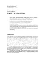
Figure 2 shows the architecture of an LTE network extended
to support static relay deployment. The gateways are in
charge of functions such as nonaccess stratum signalling,
mobility, and bearer establishment/maintenance [9]. Due to
the conventional nature of the relaying, a UE is connected
either directly to an eNB or an RN, but not to both. All
the traffic intended for a relayed UE is always routed to the
controlling eNB (also referred to as “mother eNB” or “donor
eNB”) of the concerned RN by the gateways and then routed
to the RN via the donor eNB.
As in Release 8 LTE, the eNBs control the radio resource
management (RRM) of the system [9]. Additionally, they
are also responsible for the configuration and controlling of
the RNs and their resources, routing of traffic to the RNs,
ensuring reliable communication links between the eNB and
the UE by means of outer Automatic Repeat reQuest (ARQ),
flowcontroltoallowsmaller(andcheaper)buffers in the
RNs, and so forth. Thus, the gateways do not necessarily have
to be aware of the existence of RNs in the system.
EURASIP Journal on Wireless Communications and Networking 3
MME/EPC
gateway
MME/EPC
gateway
UE
RN
UnX2
X2 X2
S1S1 S1 S1
UE
eNB
eNB
Donor eNB
Figure 2: Architecture for relay enhanced LTE network with fixed
RN deployment.
The most important task of the RN is to forward data
between the eNB and the UE. It is supposed that standard
LTE Release 8 UEs should be able to communicate via the
RNs. An RN should thus be capable of broadcasting system
level information in the same manner as the eNBs so as to
appear as a normal eNB to the UEs. Due to this, the UE-
RN interface should be the same as the Release 8 UE-eNB
interface [9, 10]. The L3 RNs considered here also support
decentralized RRM. That is, the RNs are responsible for
scheduling packets on the radio interface using the resources
that have been reserved to them by the eNB.
Since the link between the eNB and RN carries both the
traffic to the UEs and the traffic needed to control the RNs,
this interface will have different characteristics than the LTE
Release 8 air interface. It is referred to as the Un interface
and it can contain the functionalities of both the S1 interface
(Gateway-eNB: for control information as well as for data
transport), the X2 interface (eNB-eNB: for forwarding user
data, similar to the case of handover forwarding in LTE
Release 8), as well as the LTE air interface (eNB-UE: for
control information as well as for data transport).
In the architecture described so far, the RNs are assumed
to be deployed by the operator on certain locations, especially
on hotspots and locations that are highly likely to suffer from
coverage loss (cell edge and high shadowing areas), and each
RN is associated with a donor eNB. However, such a static
association limits the flexibility/efficiency of the system.
3. Dynamic Backhauling
Enabling dynamic backhauling of RNs is attractive for several
reasons. The donor eNB may be overwhelmed by a high
load within its cell, while a neighbouring cell is completely
unloaded. Moreover, static association limits the system to
support only stationary RNs, and thus mobile RNs (e.g., RNs
attached to trains) cannot be used. Running a system with
several lightly loaded cells is highly energy inefficient [11]
and efficiency can be enhanced by powering off some of the
eNBs or RNs in the system (e.g., during late night hours on
weekdays) and concentrating the system load on few eNBs.
If the eNBs that are to be powered off are relay enabled, it
would also be beneficial to associate the RNs in these cells
with other eNBs that are still active, instead of rendering
them useless when their donor eNBs are powered off. Finally,
dynamic backhauling, where the RNs can work in plug-and-
play fashion, is a requirement in a Self-Organizing Network
(SON), which is one of the important features demanded by
cellular operators for future LTE releases [12].
In order to enable dynamic backhauling, a mechanism is
needed for the RNs to discover relay-enabled eNBs that can
act as their donor eNBs. The eNBs that support relaying can
inform RNs about their relaying capability by including this
information in the message blocks they broadcast regularly
to the whole cell. This will not affect backward compatibility
as the UEs can simply ignore this extra information. As
an alternative, the RNs can query the eNBs to see if they
support relaying using a new Radio Resource Control (RRC)
protocol procedure. eNBs that do not support relaying will
not recognize this message and will thus ignore it.
The information element for identifying relaying support
thatissentbyeNBscouldincludeseveralentriessuch
as the cell load, geographical locations, where the eNB is
experiencing capacity/coverage problem and hence support
by an RN is highly needed, supported mode of relaying (L1,
L2, L3, etc ), energy saving settings, if any (e.g., when the
eNB is scheduled to be powered off next).
When an RN is powered on, it is required that it has
to be associated with an eNB before it can become fully
operational. The reason for this is that it is not yet connected
to the core network side and relaying a UE’s connection is
feasible only through the donor eNB. If relaying capability is
discovered through broadcasting, the RN, when powered on,
will listen to the different relay support broadcast messages
of neighbouring eNBs and will select the one that satisfies
acceptable criteria for donor eNB selection. On the other
hand, if relaying capability information is to be acquired via a
RRC request procedure, the RN has to send the request to the
neighbouring eNBs that it can detect and then it will select
the one that satisfies acceptable selection criteria.
Once the RN has identified the eNBs that support
relaying, it can select its donor eNB based on several criteria.
It can select the eNB with the best path gain (which in
many cases will be the cell in which the RN is geographically
located). Apart from the path gain, the interference and the
load can also be taken into consideration to find the eNB
that can provide the highest backhaul data rate to the RN.
The one with the highest load can also be selected as the
donor eNB, as it might probably need some load sharing. If
the relaying capability information contains locations where
coverage/capacity problems are being experienced by the
eNBs, this can enable the RN to associate with the eNB
that it can help optimally. Additionally, if energy saving
settings are provided, it is also beneficial to select an eNB
that is not scheduled to be powered off soon in order to
4 EURASIP Journal on Wireless Communications and Networking
avoid unnecessary handovers. A combination of several of
these criteria mentioned perviously can also be used in the
decision process.
Although it is not within the scope of this paper, it is
very informative to mention that the overall radio resource
can be partitioned between the access links and the relayed
links in an orthogonal fashion (also referred to as Hard
reuse) where the relay and access links use different resources,
or a nonorthogonal resource scheme (also referred to as
Soft reuse) where the relay and access links share the radio
resources to some extent. If multiple RNs are deployed
within a cell, spatial separation between the access links of
the RNs can guarantee a safe reuse of the resources. The
partitioning can be done either in a fixed way where a
subset of the radio resources is reserved for each RN or in
a dynamic way where the needed resources are allocated per
scheduling period. The resource splitting can be done either
in a time division multiplexing (TDM) or frequency division
multiplexing (FDM) manner. The splitting of resources
(either in frequency or time domain) will require the use
of two time or frequency slots (one for relay link and one
for access link) instead of one slot for a direct connection.
However, due to the high channel quality of the relay link
and the access links (since it is UEs with the worst direct
link quality to the eNB that end up being connected to the
RN), there will be overall gain in the end-to-end throughput
[13].
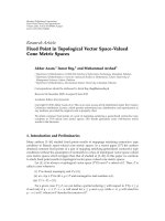
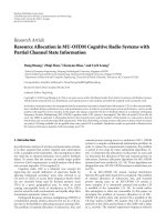
Dynamic backhauling implies the possibility of handing
over an RN and all its associated UEs to another eNB.
In order to support this, the handover mechanism of LTE
specified in [9] has to be extended, as shown in Figure 3
[14]. Based on the measurement results it is getting from
the RN, and also on other conditions such as energy
saving settings and load-balancing communication from
neighbouring cells, the donor eNB (source eNB) decides
to hand over the RN to another eNB (target eNB). This
handover decision is communicated to the target eNB. In
this handover request message, the donor eNB summarizes
the total resources required to accommodate the RN to be
handed over including its associated users.
The donor eNB can at least indicate the overall (back-
haul) traffic demands of the RN and its cell with necessary
UE contexts in detail. It can also inform the target eNB
the RN location and RN measurement reports about the
RN-target eNB radio link. The target eNB can use this
information to estimate the required radio resources to
admit the RN.
If the required resources are available, which is checked
by the admission control procedure in the target eNB,
a handover request acknowledgement message is sent to
the source eNB. The source eNB then sends a handover
command to the RN (RRC connection reconfiguration
including mobility control information), and from then on,
the data destined to the RN is forwarded to the target eNB
until the handover process is finalized.
Upon the reception of the handover command, the RN
reacts differently depending on the scenario: the source and
target eNBs have the same modes of operation (i.e., they both
use the same duplexing mode, frame structure, etc.), and
they are also synchronized with each other; or the two eNBs
operate in different modes, or they are not synchronized.
In the first case, the RN can maintain its timing, and the
UEs that it is serving do not have to change their timings.
Thus, the UEs do not have to be aware of the RN handover,
that is, the handover is transparent to the UEs, and as such
the messages in the orange box in Figure 3 are not required.
Thus in the first case, the RN detaches itself from the source
and immediately starts synchronizing with the target when it
gets the handover command.
The second case is more complex as the RN has to change
its timing and possibly other parameters such as frame struc-
ture, cell ID, scrambling code, and reference signal structure.
In this case the RN has to command the UEs to handover
to the new cell, that is, the RN after the reconfiguration
and timing changes. The messages inside the orange box in
Figure 3 arethusrequired.Thehandovercommandhasto
be sent to the UEs before the reconfiguration of the RN, that
is, before the RN synchronizes to the target eNB, because the
RN will typically change its timing or other configurations at
that time.
Once the RN has achieved L1/L2 synchronization with
the target eNB (and in the second case, in addition to
this, also when all the UEs have resynchronized with the
RN), the RN sends a handover confirmation message (RRC
connection reconfiguration complete) to the new donor
eNB. This confirmation is a composite message that includes
information about each UE that is being served through the
RN. The new donor eNB then sends out a path switch request
to the Mobility Management Entity (MME), which initiates a
user plane update request to the serving gateway. User plane
update is then performed by the serving gateway for each UE
indicated in the composite handover confirmation message.
A user plane update basically switches the downlink data
path to the target eNB. The serving gateway then sends “end
marker” packets to the source eNB, to indicate that the old
path is not going to be used anymore for the concerned UEs.
After the route update is performed, packets destined to the
UEs served by the RN will be properly routed via the new
donor eNB.
The source eNB is then advised that it can release the
resources pertaining to the RN (Release RN-UE context, as
the RN is seen as a special UE from the eNB’s point of view),
and the link between the source eNB and the RN is released.
After the forwarding of the final packet in flight to the target
eNB, the final resources are released by the source eNB and
the handover is finalized.
It should be noted that the load-balancing handover
described here is not as delay critical as a regular handover
of a UE. Thus, enough time could be taken to negotiate
and settle resource issues for the RN cell and its UEs. Upon
receiving a handover command, the RN might have to take
time to reconfigure its cell and UEs first, some UEs might
need to be downgraded or even dropped due to lack of
resources.
This need to downgrade or drop calls can be gathered
from some indication about the available resources for the
RN and its UEs in the new target cell, which can be included
either in the HO request acknowledged command or an
EURASIP Journal on Wireless Communications and Networking 5
12. Synchronization
13. UL allocation
14. RRC conn.
reconf. complete
15. RRC conn.reconf. complete
UE
RN
Source eNB
Ta rget eNB
MME
Serving gateway
0. Area restriction provided
1. Msmt control
Packet data
Packet data
Packet data
Packet data
Packet data
Packet data
Packet data
Packet data
Packet data
UL allocation
4. RN HO decision
5. HO request
6. Admission control
7. HO req. ACK
2. Msmt reports
8. RRC conn. reconf
DL allocation
DL allocation
Incl. mobility ctrl info
Detach from old cell
and synchronize
to new cell
Deliver buffered and in
transit packets to target
eNB
DL data forwarding
Buffer packets from
source eNB
9. RRC conn. reconf
10. Synchronization
11. UL allocation + TA for RN
Incl. mobility ctrl info
16. Path switch request
End maker
End maker
17. User plane update
request
18. Switch DL path
19. User plane update
response
20. Path switch request ACK
21. Release RN-UE
context
22. Release resources
L3 signalling
L1/L2 signalling
User data
Figure 3: Handover of an RN and all its associated UEs in an LTE network that supports dynamic RN deployment.
6 EURASIP Journal on Wireless Communications and Networking
additional signal sent from the target eNB. However, the RN
might avoid these downgrades and call drops by initiating
a separate handover of the concerned UEs to another RN
or eNB. These additional handovers can be initiated either
after the RN handover is finalized or even before that
once the HO command is received. Doing these additional
handovers before the RN handover is finalized will save
the UEs from performing two consecutive handovers and
thus it reduces the total handover delay. However, such pre-
emptive handovers are not foolproof as resource reallocation
and repartitioning after the RN handover is finalized might
have been sufficient to provide the required quality for all
the connections. Thus, the pre-emptive handovers should be
initiated only when there is a very high disparity between
the required resources of the relayed UEs and the available
resources in the target cell.
Some UEs may have to be assigned to different resources,
if the currently used resources collide with resources used
for other purposes in the new eNB, for example, resources
that the target eNB intends to use to communicate with the
RN. It is possible to assign resources fully dynamically in
LTE via fast scheduling and these allocations can be changed
accordingly on the fly. On the other hand, for semipersistent
scheduling, UEs are granted resources for a longer time
interval and these grants need to be reconfigured for the
handover. This can possibly happen even before handover
initiation (i.e., before sending the handover command to the
UE), immediately afterwards or after the re-establishment of
the link.
Apart from dynamic association of RNs and eNBs,
dynamic backhauling also allows the operator to activate and
deactivate RNs in a certain area as needed in order to deploy
extra capacity needed to satisfy peaks in users’ demand,
but at the same time save energy when it is not needed by
simply powering off unnecessary RNs. Figure 4 illustrates the
deactivation procedure.
Based on the measurements from the RN and load
conditions in neighbouring cells, the donor eNB decides to
deactivate the RN, as shown in Figure 4.ThedonoreNB
sends out a deactivation command to the RN, and the RN
initiates a handover procedure for all its users. Once the
handover for each relayed UE is finalized, the RN deactivates
itself and sends a deactivation confirmation message to the
donor eNB.
The deactivation command from the donor eNB to the
RN can contain parameters needed for future reactivation of
the RN. This can include timer values such as a sleep interval
during which the RN completely shuts down its transceiver,
and also on-duration periods during which the RN will listen
on a common control channel such as a paging channel to
determine if the donor eNB is trying to reactivate it. This
procedure can be done in a way similar to the Discontinuous
Reception (DRX) procedure of LTE [9].
4. Multimode Relays
As one of the main driving forces behind the deployment
of RNs is the low infrastructure cost, RNs in LTE-Advanced
use in-band wireless links based on the LTE-Advanced air
interface instead of using wired links or dedicated out-of-
band (e.g., microwave) wireless links.
Though this is a cheap and simple solution, there might
be a need to support out-of-band wireless links. This is
especially significant in scenarios/durations where the radio
resources are limited and not enough resources can be
reserved to the backhaul link without compromising the
quality of users that are directly being served by the eNB.
Thus, it can be beneficial to use multiple interfaces in the
backhaul link, not only to increase the system performance,
but also to add robustness to the system by switching
between the interfaces, or even sharing the load between
the multiple interfaces when the need arises. The prevalence
of overlay networks where multiple networks (e.g., GPRS,
UMTS, HSPA, etc.) are available at a given site facilitates the
possibility of switching/load-sharing.
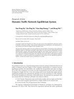
Figure 5(a) shows the different interfaces in a relay
enhanced LTE network. As can be seen in the figure,
the backhaul link is using the LTE-Advanced air interface
while the access link between the RN and the UE is using
LTE Release 8 air interface for backward compatibility
purposes. In Figure 5(b),weproposeanewarchitecture
where additional interfaces are available (Ib2 to IbN in the
figure) in the backhaul link apart from the LTE-Advanced air
interface.
Multimode RNs should coexist with single mode RNs
(those that support only the LTE-Advanced interface), and
as such, it is necessary for the eNBs to find out the
interfacing options available at the RN. The exchange of
the interfacing capability of the RN can be done either
during the association of the eNB and the RN (i.e., when
the RN is first activated or handed over to another eNB
as described in Section 3), or using separate RRC interface
capability messages after the association is finalized. This
interface capability request will be ignored by single mode
RNs as they are not aware of this procedure, and thus the eNB
can safely assume that the concerned RN is a single mode
RN if it does not get a response after a certain number of
repetitions of the interface capability request.
The LTE-Advanced air interface is the default interface to
be used between the donor eNB and the RN. However, once
the association procedure is complete and the donor eNB is
aware of the interfaces supported by the RN, the interface
to be used can be modified according to system need. The
interface selection decision is controlled by the eNB.
The optimal interface can be chosen based on several
criteria. The interface that belongs to the network with
the lowest load, or in other words, the network that can
provide the highest capacity for the relay link is an obvious
choice. However, the cheapest network, from the operator’s
operating expense (OPEX) point of view, or the network that
optimizes certain resources like energy can also be chosen.
The main advantage of using multimode RNs is to
dynamically modify the interface to be used for the backhaul
link for optimum system performance. Thus, there is a need
to deactivate the currently active interface and (re)activate
another interface. The decision to change the interface is
done in a similar fashion as in the case of the interface
EURASIP Journal on Wireless Communications and Networking 7
UE
Source eNBSource RN Target eNB Target RN
MME
Serving gateway
0. Area restriction provided
1. Msmt ctrl
1. Msmt ctrl
UL allocation
Packet data
Packet data
Packet data
2. Msmt
reports
2. Msmt
reports
5. HO each relayed UE to source eNB, target eNB or target RN
3. RN deactivation
decision
4. Deactivate
6. Deactivate
confirm
L3 signalling
L1/L2 signalling
User data
Figure 4: Deactivation of an RN in an LTE network that supports dynamic RN deployment.
selection procedure, that is, based on load, throughput, cost
factors, or other reasons.
Based on the aforementioned factors, measurement
results that it is getting from the RN, and other conditions
such as load-balancing communication from neighbouring
cells, the donor eNB decides to change the interface for the
backhaul link. This decision is communicated to the RN and
the RN deactivates the current interface and (re)activates
the new one. The relayed UEs should not be aware of the
interface changes.
Several factors have to be considered in order to make
sure that no user data is lost and all active bearers that
belong to relayed UEs are not disconnected. Adequate radio
resources have to be allocated on the new network before the
interface modification is initiated to ensure that the Quality
of Service (QoS) of active bearers will still be satisfied.
Also, any outstanding data on the old interface should be
forwarded to the new interface, both in the donor eNB and
RN, before the old interface is deactivated.
Though the possibility to switch between the different
interfaces available to a multimode RN is important to
transfer the connection to the network for optimal overall
system utilization, there might be cases when one network
is not able to provide all the needed resources for all the
relayed UEs. Thus, it is essential to enable the simultaneous
activation of multiple interfaces of a multimode RN.
The measurement reports from the RNs that may
lead to interface activation/deactivation can be sent either
periodically or triggered when certain thresholds related to
the allowable load values on a given interface are reached.
A combination of periodic and event based measurement
reporting can also be used. For example, periodic reporting
with a long reporting period can be used under nor-
mal conditions to minimize measurement overhead, but
threshold-based triggering can override the periodicity and
send the reports in order to avoid unnecessary delay in the
interface activation/deactivation which can possibly lead to
the downgrading or even the dropping of active bearers.
Just as in the case of a simple UE handover between two
eNBs, ping-pong effects can be prevented using hysteresis
thresholds.
The two main reasons for activating multiple interfaces
are either that a new bearer has to be established by a relayed
UE and there are not enough resources for the backhaul link
for this connection, or that a new bearer is to be established
by a directly connected UE but there are not enough radio
resources, unless some resources being used for the backhaul
link are freed. In the first case, the new bearer will be
8 EURASIP Journal on Wireless Communications and Networking
MME/EPC
gateway
UE
RN
LTE-A
LT E
S1
Donor eNB
(a)
MME/EPC
gateway
UE
RN
LT E
S1
Donor eNB
Ib1
(LTE-A)
Ib2
IbN
(b)
Figure 5: Interfaces between different network elements, (a) single mode RNs, (b) multimode RNs.
associated with the new interface and the rest of the bearers
is not affected. In the second case, on the other hand, the
donor eNB has to select a relayed bearer or even directly
connected bearers which have to be transferred to the new
network, so that the new direct bearer can be admitted to the
cell. Measures have to be taken on the data of the selected
bearers in order to avoid user data loss and dropped bearers.
5. Relay Node-Home Enhanced NB Integration
3GPP is currently standardizing home eNBs, also known
as “femto-cells” [15]. Home eNBs are similar to WLAN
access points and will be installed in residence and office
buildings where there is already an access to Internet, for
example, via a wired system. They will appear as normal
eNBs to the UEs and they will access the core network
of the operator via the Internet. Generic Access Network
(GAN), also known as Unlicensed Mobile Access (UMA),
is chosen by 3GPP as the way to provide the interfacing to
the operator’s core network through the Internet. Though
home eNBs seem to be an attractive solution for nonreal
time (NRT) services, there might be some real time (RT)
services that have very strict QoS requirements that might
not be met via the Internet connection (e.g., when there
is congestion). In order to resolve this issue, we extend the
concept of multimode RNs described in Section 4 to support
also home eNB functionality.
Figure 6 shows a multimode RN enhanced to support
home eNB functionality. As can be seen from the figure, there
is a new interface, which we refer to as S1
RN
, between the
RN and the core network elements using DSL or cable, in
a similar fashion as a home eNB. Note that S1
RN
does not
necessarily have to be a wired interface, as long as it gives a
direct connection to the Internet, which is then routed to the
core network of the operator. Note that L3 or higher layer
relays are required to enable this functionality as routing via
the Internet is required.
MME/EPC
gateway
UE
RN
Internet
LT E
S1
S1
RN
Donor eNB
.
.
.
Ib1
(LTE-A)
Ib2
IbN
Figure 6: A multimode RN enhanced with home eNB functionality.
Such an RN that is equipped with a wired/wireless access
to the Internet can act as a home eNB when the need arises,
and can operate in several modes.
(1) It can use the Internet as an alternative interface to
the LTE-Advanced interface; that is, the data for the
relayed users will be routed from the eNB to the RN
via the core network and the Internet, and the RN
forwards it to the relayed UEs via the LTE air interface
(and vice versa for uplink traffic).
(2) It can use the Internet for load balancing where some
of the bearers will be supplied via the Internet as
in the first case, and the rest is provided by LTE-
Advanced or/and the other wireless interfaces in the
backhaul.
(3) It can operate as a stand alone home eNB where the
RN is directly connected via the S1
RN
interface to the
core network.
EURASIP Journal on Wireless Communications and Networking 9
The first two options require that the system has to be
configured to support home eNBs (i.e., connection to the
operator’s network via the Internet) and a modification in
the GAN in order to route the data back and forth via the
eNB instead of the gateways. This means, while the RN is
connected to the eNB logically, this connection is realized
physically via the Internet and the GAN instead of a direct
physical link between the RN and eNB that has been assumed
so far in the previous sections.
The third option is basically the same as a home eNB
operation, and the donor eNB does not have to be concerned
with the data for the relayed UEs any more as they are
transported directly to the gateway without the need to reach
the donor eNB. However, it is still beneficial to maintain a
connection between the donor eNB and the RN, which uses
very few radio resources, in order to enable the RN to switch
back to the “normal RN” mode when enough radio resources
become available for the backhaul.
The deployment of RNs that can also simultaneously act
as home eNBs will not only make the system more flexible by
creating alternatives for load sharing and load switching, it
also makes the system more robust to failures. That is, when
the radio resources in one of the backhaul links of the RN
are exhausted, there is still a way to transfer the load via the
home eNB interface and vice versa.
A typical usage scenario for a home eNB enabled RN
is to use the wireless backhaul connections for RT services
with very strict QoS requirements while using the Internet
for NRT services and for RT services with more relaxed QoS
requirements. This is due to the fact that the operator has full
control over the different (wireless) networks available for
the backhaul link, but not on the Internet. Notable latency
may be expected due to the longer path needed for the
packets if the RN is operating as a home eNB for the first two
options. For example in the uplink, in the home eNB case the
path is UE-RN-GAN-Gateways while for the first and second
options (in the home eNB mode), it will be UE-RN-GAN-
donor eNB-GAN-Gateways. That is, option 1 and home eNB
mode of option 2 are more suitable for NRT services or RT
services with relaxed QoS requirements, while the normal
relay mode of option 2 (and to some extent, option 3) is more
suitable for RT services with strict QoS requirements.
6. Distributed Relaying
When we refer to relaying, especially in the context of relay
enhanced LTE, the normal assumption is that there is a one-
to-one association between RNs and eNBs (i.e., multiple RNs
can be connected through an eNB, but an RN is connected
only to one eNB). Though such an architecture, as shown
in Figure 2, is a straightforward and simple solution to
enable relaying in LTE, it might limit the system performance
because the end-to-end performance of relayed UEs will be
constrained by the capacity available on the backbone link
between the donor eNB and the core network (i.e., the link
that is accessible through the S1 interface). For example, even
if there are sufficient radio resources for the relay link, the
performance of relayed UEs can degrade if there is congestion
MME/EPC
gateway
MME/EPC
gateway
UERN
Un
Un
Un
X2
X2 X2
S1S1
S1 S1
UE
eNB
eNB
Donor eNB
Figure 7: Architecture for enabling distributed relaying in LTE.
in the backbone. In practice, S1 links are expensive, and
usually operators do not deploy enough capacity to support
the maximum cell capacity offered by the air interface.
Apart from the backbone that can turn out to be a
bottleneck, we can have insufficient resources on the relay
link with the donor eNB while we have a lightly loaded
neighbouring cell. In [12], it is proposed that neighbouring
cells can communicate their load information via the X2
interface, which will then probably lead to the handover of
some of the users to the neighbour cell. However, the S1
links of the two eNBs (assuming they use different S1 links)
are not shared; that is, the load sharing is performed by
handing over some of the users to the slightly loaded cell.
Though handover to the lightly loaded cell is an option, it
is not a totally flexible solution as back and forth handover
of the relay and all its relayed UEs between eNBs can be
an expensive procedure. Not only that, with handover we
are only able to use the capacity of just one neighbour
cell, instead of the sum of the available capacity in all the
neighbouring cells.
In order to enable many-to-many connections between
RNs and eNBs, the RNs can be connected to multiple eNBs
through the Un interface, or one connection can be kept
with the donor eNB and this eNB distributes the data to
neighbouring eNBs via the X2 interface. Since the focus of
this paper is on the radio access network, rather than the
transport network, we will focus only on the first approach.
Figure 7 shows the architecture of a relay enhanced
LTE system modified to support multiple Un connections.
Originally, the RN is associated only with the donor eNB,
and it remains so if the required QoS can be achieved for
the relayed UEs. Then, due to congestion on the S1 link
and/or unfavourable conditions on the Un radio link, the
performance of the relayed UEs starts to degrade. At this
point, based on the latest measurement reports by the RN
regarding neighbouring eNBs, the donor eNB may contact
suitable neighbouring eNBs to find out how much and which
10 EURASIP Journal on Wireless Communications and Networking
resources they are willing to share in providing additional Un
radio links for the RN. These include all the necessary radio
network identifiers and radio configuration information for
the RN to establish and communicate with and via the
relevant neighbouring eNB(s).
Once an agreement is reached between the donor eNBs
and its neighbours, the donor eNB may contact a central
network controller (i.e., a new functionality introduced in,
e.g., the gateway to support SONs) to set up corresponding
coordinated S1 links with indicated neighbouring eNBs for
the RN and request the RN to establish additional Un
radio connection with the concerned eNBs according to the
assigned configurations.
The RN will still have only one donor eNB that is
responsible for network coordination and control but this
donor eNB role can be switched between the different eNBs
depending on the resources available in the different cells.
The RN will be notified either by the donor eNB or by the
new eNB(s) as to which resources it can use to communicate
with the new eNB(s).
Thus, in the uplink, the RN from then onwards will send
data to a given eNB if the resources used are those assigned
for communicating with that eNB. The data is delivered via
multiple S1 links to the gateway. The gateway may have to
resequence the data arriving from the different eNBs before
forwarding them to the destination, similar to the case of
handover.
The downlink operation may require the gateway to
distribute the data to multiple eNBs. The gateway can
be informed which eNBs are connected to the RN and
depending on the load of the S1 links of these involved eNBs,
the gateway will route the data over the different S1 links.
Data belonging to the same bearer may end up being routed
via different S1 links, and thus there should be a mechanism
on the RN to resequence the data flow. Though this way of
data distribution is optimal from the usage of the S1 link, it
is suboptimal as it does not consider the load on the relay
link of the different eNBs. A periodic reporting of the relay
link load of the different eNBs could thus be beneficial for
the gateway in order to distribute the load reasonably.
Another way to distribute the data is to let the eNBs
and the gateway collaborate to decide which bearers should
be delivered through which eNBs, and the gateway routes
the downlink data based on this agreement. This is simpler
than the fully gateway controlled data distribution described
above, as it does not require the resequencing of data that
belong to the same bearer. However, it is not as flexible and
might lead to suboptimal decisions.
In case multimode RNs are used, the distributed S1
comes handy when the available resources in one network
are not enough for the backhaul link and some of the
connections have to be transferred to another network (i.e.,
the RN will have active connections with several eNBs via
different network interfaces).
The support of distributed S1 relaying described in
this paper is completely transparent to the UEs. However,
changes are required in the RN, eNB, and the gateways.
For distributing S1 via several X2 links, actually no changes
are required at the RN. The most significant change is
the decision mechanism at the eNB, RN, and gateways as
to where to route the data, and the resequencing of data
arriving via several S1 interfaces at the gateway and data
coming via several Un interfaces at the RN. The support
of distributed S1 interface will not only make the system
more robust to problems related to transport network
under dimensioning, but it will also make the system more
flexible by creating alternatives for load sharing and load
switching.
7. Conclusions
Relaying is expected to play a pivotal role in LTE-Advanced
networks, by helping to extend the coverage around cell
edges and high shadowing environments and also increas-
ing the capacity in hotspots. Thus, we have proposed a
flexible architecture that will enable dynamic relaying in
LTE networks, while still maintaining backward compati-
bility with LTE Release 8 user equipments. The dynamic
backhauling configuration proposed in this paper paves
the way to flexible, efficient, and self-optimizing multihop
cellular networks. Operators do not have to put extensive
effort in finding the most optimal locations for placing
relay nodes through exhaustive radio planning as optimal
eNB-RN associations can be made on the fly. This can
lead to big reductions in the planning costs required for
enabling relaying in future releases of LTE, enabling even
end-users to be able to install relays as easily as WLAN
access points. We have also proposed multimode relays that
support several network interfaces. This will not only make
the system more flexible by creating alternatives for load
sharing/switching between different links; it also makes the
system more robust to failures. That is, when the resources
of one network are exhausted, there is still a possibility
to transfer the load fully or partially to other networks,
or even using a connection via the Internet, if the RN is
enabled to support home eNB functionality. Finally, we have
proposed a distributed relaying architecture with many-to-
many connections between relay nodes and eNBs, to make
the system more robust to problems related to transport
network under dimensioning, and also enable load sharing
between different cells.
References
[1] H. Yanikmoeroglu, “Fixed and mobile relaying technologies
for cellular networks,” in Proceedings of the 2nd Workshop in
Applications and Services in Wireless Networks (ASWN ’02),pp.
75–81, Berlin, Germany, July 2002.
[2] “IST-WINNER Project,” />[3] IEEE STD.2007.4312731, “Draft Standard for Local and
Metropolitan Area Networks–Part 16: Air Interface for Fixed
and Mobile Broadband Wireless Access Systems : Multihop
Relay Specification,” 2007.
[4] IEEE P802.16j Base Line Document, “Part 16: Air Interface
for Fixed and Mobile Broadband Wireless Access Systems:
Multihop Relay Specification,” 2007.
[5] P. E. Mogensen, et al., “LTE-Advanced: The path towards giga-
bit/s in wireless communications,” Wireless Vitae Conference,
May 2009.
EURASIP Journal on Wireless Communications and Networking 11
[6] 3GPP TR 36.813 v0.1.1, “Further advancements for E-UTRA,
physical layer aspects,” November 2008.
[7] S. Valentin, et al., “Cooperative wireless networking beyond
store-and-forward: perspectives for PHY and MAC design,” in
Proceedings of the Wireless World Research Forum (WWRF ’06),
WG3 whitepaper, 2006.
[8]R.Pabst,B.H.Walke,D.C.Schultz,etal.,“Relay-based
deployment concepts for wireless and mobile broadband
radio,” IEEE Communications Magazine, vol. 42, pp. 80–89,
2004.
[9] 3GPP TS 36.300 v8.7.0, “E-UTRA and E-UTRAN overall
description : stage 2 (release 8),” December 2008.
[10] E. Dahlman, et al., 3G Evolution: HSPA and LTE for Mobile
Broadband, Academic Press, New York, NY, USA, 2007.
[11] T. Ruuska, “Adaptive power management in telecommunica-
tion network,” US patent no. 6584330, June 2003.
[12] 3GPP TR 36.902, “Self-configuring and self-optimizing net-
work use cases and solutions (release 9),” September 2008.
[13] T. Wirth, V. Venkatkumar, and T. Haustein, “LTE-Advanced
relaying for outdoor range extension,” in Proceedings of the
IEEE Vehicular Technolog y Conference (VTC ’09), Anchorage,
Alaska, USA, September 2009.
[14] O. Teyeb, V. Van Phan, B. Raaf, and S. Redana, “Handover
framework for relay enhanced LTE networks,” in Proceedings
of the IEEE International Conference on Communications (ICC
’09), Dresden, Germany, June 2009.
[15] 3GPP TS 25.467 V9.0.1, “UTRAN architecture for 3G Home
Node B (HNB);Stage 2,” Sep. 2009.