Báo cáo hóa học: " Research Article Effects of Carrier Frequency Offset, Timing Offset, and Channel Spread Factor on the Performance of Hexagonal Multicarrier Modulation Systems" doc
Bạn đang xem bản rút gọn của tài liệu. Xem và tải ngay bản đầy đủ của tài liệu tại đây (1.01 MB, 8 trang )
Hindawi Publishing Corporation
EURASIP Journal on Wireless Communications and Networking
Volume 2009, Article ID 802425, 8 pages
doi:10.1155/2009/802425
Research Article
Effects of Carrier Frequency Offset, Timing Offset, and
Channel Spread Factor on the Perfor mance of Hexagonal
Multicarrier Modulation Systems
KuiXuandYuehongShen
Institute of Communications Engineering, PLA University of Science and Technology, No. 2 Biaoying Road,
Yudao Street, Nanjing 210007, China
Correspondence should be addressed to Kui Xu, xiancheng
Received 17 May 2008; Revised 6 October 2008; Accepted 31 January 2009
Recommended by Mounir Ghogho
Hexagonal multicarrier modulation (HMM) system is the technique of choice to overcome the impact of time-frequency dispersive
transmission channel. This paper examines the effects of insufficient synchronization (carrier frequency offset, timing offset) on
the amplitude and phase of the demodulated symbol by using a projection receiver in hexagonal multicarrier modulation systems.
Furthermore, effects of CFO, TO, and channel spread factor on the performance of signal-to-interference-plus-noise ratio (SINR)
in hexagonal multicarrier modulation systems are further discussed. The exact SINR expression versus insufficient synchronization
and channel spread factor is derived. Theoretical analysis shows that similar degradation on symbol amplitude and phase caused
by insufficient synchronization is incurred as in traditional cyclic prefix orthogonal frequency-division multiplexing (CP-OFDM)
transmission. Our theoretical analysis is confirmed by numerical simulations in a doubly dispersive (DD) channel with exponential
delay power profile and U-shape Doppler power spectrum, showing that HMM systems outperform traditional CP-OFDM systems
with respect to SINR against ISI/ICI caused by insufficient synchronization and doubly dispersive channel.
Copyright © 2009 K. Xu and Y. Shen. This is an open access article distributed under the Creative Commons Attribution License,
which permits unrestricted use, distribution, and reproduction in any medium, provided the original work is properly cited.
1. Introduction
Multicarrier modulation (MCM) is a popular transmission
scheme in which the data stream is split into several sub-
streams and transmitted, in parallel, on different subcarriers.
We consider MCM over time-varying multipath propagation
channels which spread the MCM signal simultaneously
in both the time and frequency domains. This spreading
induces both intersymbol interference (ISI) and intercarrier
interference (ICI) which complicate data demodulation. We
will refer to channels that are time dispersive and frequency
dispersive as doubly dispersive (DD) channels.
Orthogonal frequency-division multiplexing (OFDM)
systems with guard time interval or cyclic prefix can prevent
ISI, but do not combat ICI because they are based on
rectangular-type pulses. In order to overcome the aforemen-
tioned drawbacks of OFDM systems, several pulse-shaping
OFDM systems were proposed [1–15]. Most works on pulse
design exclusively dealt with rectangular time-frequency
(TF) lattices. It is shown that transmission in rectangular
lattices is suboptimal for doubly dispersive channels [9]. By
using sphere covering theory, the authors have demonstrated
that lattice OFDM (LOFDM) systems, which are OFDM
systems based on hexagonal-type lattices, provide better
performance against ISI/ICI. However, LOFDM confines
the transmission pulses to a set of orthogonal ones. As
pointed out in [2, 10, 13, 16], these orthogonalized pulses
destroy the time-frequency (TF) concentration of the initial
pulses, hence lower the robustness to the time and frequency
dispersion caused by the propagation channel.
In [16], the authors abandoned the orthogonality con-
dition of the modulated pulses and proposed a multicar-
rier transmission scheme on hexagonal lattice named as
hexagonal multicarrier modulation (HMM) by regarding
signal transmission as tiling of the TF plane. To optimally
combat the impact of the propagation channels, the lattice
parameters and the pulse shape of modulation waveform are
jointly optimized to adapt to the channel scattering function.
2 EURASIP Journal on Wireless Communications and Networking
It is shown that the hexagonal multicarrier transmission
systems obtain lower energy perturbation, hence outperform
OFDM and LOFDM systems from the robustness against
channel dispersion point of view.
Synchronization is considered as a key factor of designing
multicarrier modulation system receiver. The synchroniza-
tion precision significantly affects the receiver performance
and usually depends on the precision of carrier frequency
offset estimation and symbol timing. A generalized frame-
work for the prediction of OFDM system performance in
the presence of carrier frequency offset (CFO) and timing
offset (TO), including the transmitter and receiver pulse
shapes as well as the channel, is presented in [17]. The
signal-to-interference-plus-noise ratio (SINR) performance
low bound on the effects of Doppler spread in OFDM system
is studied in [18].
In this paper, our attention is focused on the analysis
of the effects of CFO and TO on the amplitude and phase
of the demodulated symbol by using a straightforward but
suboptimum projection receiver [2, 9, 10, 12, 13]inhexag-
onal multicarrier modulation systems. Furthermore, effects
of CFO, TO, and channel spread factor on the performance
of SINR in hexagonal multicarrier modulation systems are
further discussed. The exact SINR expression versus CFO,
TO, and channel spread factor is derived. Both theoretical
analysis and simulation results show that similar degradation
on symbol amplitude and phase caused by insufficient syn-
chronization is incurred as in CP-OFDM transmission. Our
theoretical analysis is confirmed by numerical simulations,
showing that HMM systems outperform traditional CP-
OFDM systems with respect to SINR against ISI/ICI caused
by CFO, TO, and doubly dispersive channel.
2. Sig n al Transmission and TF Latt i ce
It is shown in [16, 19] that signal transmission can be
viewed as tiling of the TF plane. In practice, almost all
communication systems transmit the information symbols
in a regular way, and the underlying tiling forms a lattice
in the TF plane. In a nutshell, a lattice V in K-dimensional
Euclidean space
R
K
is a set of points arranged in a highly
regular manner. Since we consider the signal transmission
in the TF plane in this correspondence, we only confine our
attention to two-dimensional (2D) case.
Specifically, in OFDM system with symbol period T
and subcarrier separation F, the transmission functions of
OFDM system consist of translations and modulations of a
single prototype g(t), which constitute a Weyl-Heisenberg
system and create a 2D rectangular lattice with generator
matrix
V
=
T 0
0 F
. (1)
Conventional time-division multiplex (TDM) mode and
frequency-division multiplex (FDM) mode can be viewed as
transmission on a one-dimensional (1D) lattice along the
time axis and frequency axis, with generators
T 0
T
and
F 0
T
, respectively, where the superscript (·)
T
represents
the transpose.
The lattice density is given by ρ
= 1/
det(V
T
V),
where det(
·) denotes the determinant. The quantity ρ
corresponds to the symbol density in the TF plane, which
was known as signaling efficiency to represent the number of
symbols per second per hertz. For signal transmission with
general transmission pattern V, the transmitted signal can be
expressed as
s(t)
=
z
c
z
g
t, Vz
,(2)
where c
z
is the data symbol indexed by z, which is usually
taken from a specific signal constellation and assumed to
be independent and identically distributed (i.i.d.) with zero
mean and average power σ
2
c
; g(t, Vz) is the modulation pulse
associated with c
z
and z = [m,n]
T
, m ∈ M, n ∈ N , while
m and n can be regarded as the generalized time index and
subcarrier index, respectively. Moreover, M and N denote
the sets from which m, n can be taken.
It is well known that when a signal is transmitted over
mobile radio channel, the energy of one symbol data will
spread out to neighboring symbols due to the time and
frequency dispersion, which produces ISI/ICI and degrades
the system performance. In the view of signal transmission
on lattice in the TF plane, the system performance is mainly
determined by two factors:
(i) the time-frequency localization of pulse shape g(t);
(ii) the distance between adjacent time-frequency lattice
point.
A better TF-concentrated pulse would lead to more
robustness against the energy leakage. It is obvious that
the larger the distance, the less the perturbation among the
transmitted symbols.
3. Hexagonal Multicarrier Transmission
System [16]
It is well known that the Gaussian pulse
g
σ
(t) =
2
σ
1/4
e
−(π/σ)t
2
(3)
has the best energy concentration in the sense that it
achieves the equality in the Heisenberg uncertainty principle
W
t
W
f
≥ 1/4π,whereW
2
t
and W
2
f
are the centralized
temporal and spectral second-order moments, respectively
[20]. By the Heisenberg uncertainty principle, any signal
cannot be arbitrarily concentrated in the time and frequency
directions simultaneously, which suggests that they must
occupy some area in the TF plane.
The product W
t
W
f
characterizes the energy concentra-
tion of a pulse in the TF plane. The smaller the value of
W
t
W
f
is, the more concentrated the pulse will be. Hence,
EURASIP Journal on Wireless Communications and Networking 3
the Gaussian pulse is the natural choice as modulation
waveform, in an attempt to achieve minimum energy pertur-
bation over TF dispersive channels. Note that the parameter
σ determines the energy distribution of the Gaussian pulse in
the time and frequency directions, respectively. To be more
specific, we have σ
= W
t
/W
f
.
The ambiguity function of prototype is defined by
A
g
σ
(τ, υ) =
∞
−∞
g
σ
(t)g
σ∗
(t −τ)e
−j2πυt
dt
= e
−(π/2)((1/σ)τ
2
+σv
2
)
e
−jπτv
,
(4)
where (
·)
∗
denotes the complex conjugate. It can be viewed
as the 2D correlation between g(t) and its shifted version by τ
in time and υ in frequency in the TF plane. We can conclude
from (4) that the ambiguity function of the Gaussian pulse is
an ellipse in the TF plane.
As pointed out in [16], for a given signaling efficiency, the
information-bearing pulses arranged on a hexagonal lattice
can be separated as sufficiently as possible in the TF plane.
An example of hexagonal transmission pattern
V
hex
=
⎡
⎢
⎢
⎢
⎣
T
2
0
F
2
F
⎤
⎥
⎥
⎥
⎦
(5)
which is named as hexagonal multicarrier modulation is
illustrated in Figure 1.
For signal transmission with general transmission pat-
tern V
hex
, the transmitted signal can be expressed as
s(t)
=
z
c
z
g
σ
t, V
hex
z
=
m
n
c
m,n
g
σ
t −m
T
2
e
j2π(m+2n)(F/2)t
,
(6)
where g(t, V
hex
z) is the modulation pulse associated with
c
z
. The signaling efficiency can be easily calculated as ρ =
1/
det(V
T
hex
V
hex
) = 2/TF.
It is shown in [16] that the symbol energy perturbation
function is dependent on the channel scattering function and
the pulse shape. To optimally mitigate ISI/ICI caused by the
mobile radio channels, the choices of modulation pulse and
lattice generate matrix parameters should be matched to the
maximum multipath delay spread and Doppler shift. The
optimal system parameters for TF dispersive channels with
exponential-U scattering function can be chosen as [16]
σ
=
W
t
W
f
= α
τ
rms
f
d
=
√
3
T
F
,
σ
=
W
t
W
f
= α
τ
rms
f
d
=
1
√
3
T
F
.
(7)
Time
Frequency
F
T
Figure 1: Partition of the hexagonal lattice into a rectangular
sublattice V
rect1
(denoted by ) and its coset V
rect2
(denoted by ).
The baseband doubly dispersive channel can be modeled
as a random linear operator H:
H[s(t)]
=
τ
max
0
f
d
−f
d
H(τ, υ)s(t −τ)e
j2πυt
dτ dυ,(8)
where H(τ, υ) is called the delay-Doppler spread function,
which is the Fourier transform of the time-varying impulse
response of the channel h(t, τ)withrespecttot.Moreover
τ
max
and f
d
are the maximum multipath delay spread and
the maximum Doppler frequency, respectively. In wide-sense
stationary uncorrelated scattering (WSSUS) assumption, the
channel is characterized by the second-order statistics:
E
H(τ, υ)H
∗
τ
1
, υ
1
=
S
H
(τ, υ)δ
τ −τ
1
δ
υ − υ
1
,(9)
where E[
·] denotes the expectation and S
H
(τ, υ) is called the
scattering function, which characterizes the statistics of the
WSSUS channel. We assume that E[H(τ, υ)]
= 0. Without
loss of generality, we use
τ
max
0
f
d
−f
d
S
H
(τ, υ)dτ dυ = 1, which
means that the channel has no overall path loss.
It is shown in Figure 1 that the original hexagonal lattice
can be expressed as the disjoint union of a rectangular
sublattice V
rect1
and its coset V
rect2
. The transmitted signal
(6) can be expressed as
s(t)
=
m
n
c
1
m,n
g(t −mT)e
j2πnFt
+ c
2
m,n
g
t −
m +
1
2
T
e
j2π(n+1/2)Ft
=
m
n
c
1
m,n
g
1
m,n
(t)+c
2
m,n
g
2
m,n
(t)
,
(10)
where c
1
m,n
and c
2
m,n
represent the symbols coming from V
rect1
and V
rect2
,respectively.
The received signal is
r(t)
= H[s(t)] + n(t), (11)
4 EURASIP Journal on Wireless Communications and Networking
where n(t) is the AWGN having variance σ
2
n
. To obtain the
data symbol
c
i
m,n
, the receiver [2, 9, 10, 12, 13]projectson
g
i
m,n
(t), i = 1, 2, that is,
c
i
m,n
=
r(t), g
i
m,n
(t)
=
H[s(t)], g
i
m,n
(t)
+
n(t), g
i
m,n
(t)
=
j
m
,n
c
j
m
,n
H
g
j
m
,n
(t)
, g
i
m,n
(t)
+
n(t), g
i
m,n
(t)
.
(12)
4. Effects of Nonideal Transmission Conditions
Without loss of generality, we assume a timing offset Δt
and carrier frequency offset Δ f ; the received data symbol
by using a projection receiver [2, 9, 10, 12, 13]canbe
expressed as
c
i
m,n
=
e
j2πΔ ft
r(t), g
i
m,n
(t −Δt)
=
m
,n
c
i
m
,n
e
j2πΔ ft
H
g
i
m
,n
(t)
, g
i
m,n
(t −Δt)
+
n(t), g
i
m,n
(t −Δt)
=
c
i
m,n
e
j2πΔ ft
H
g
i
m,n
(t)
, g
i
m,n
(t −Δt)
ξ
N+I
⇐=
⎧
⎪
⎪
⎪
⎪
⎪
⎪
⎪
⎨
⎪
⎪
⎪
⎪
⎪
⎪
⎪
⎩
+
m
/
=m, n
/
=n
c
i
m
,n
e
j2πΔ ft
H
g
i
m
,n
(t)
, g
i
m,n
(t−Δt)
+
m
,n
, j
/
=i
c
j
m
,n
e
j2πΔ ft
H
g
j
m
,n
(t)
, g
i
m,n
(t−Δt)
+
n(t), g
i
m,n
(t −Δt)
= e
−j2π(Δ f (m+(i−1)/2)T+(n+(i−1)/2)FΔt)
×c
i
m,n
A
H
τ
max
, f
d
, Δt, Δ f
+ ξ
N+I
,
(13)
where
A
H
τ
max
, f
d
, Δt, Δ f
=
τ
max
0
f
d
−f
d
H(τ, υ)A
∗
g
(τ + Δt, υ + Δ f )
·e
j2πυ(m+(i−1)/2)T
e
−j2π(n+(i−1)/2)Fτ
dτ dυ.
(14)
The demodulated signal now consists of a useful portion
and disturbances ξ
N+I
caused by ISI, ICI, and AWGN.
Concerning the useful portion, the transmitted symbols c
i
m,n
are attenuated by A
H
(τ
max
, f
d
, Δt, Δ f )whichiscausedby
doubly dispersive channel, timing offset, and carrier fre-
quency offset. Meanwhile, the transmitted symbols rotated
by a time-variant phasor
φ
=−j2π
Δ f
m +
(i
−1)
2
T +
n +
(i
−1)
2
FΔt
.
(15)
5. Effects of TO, CFO, and DD Channels
on SINR
The energy of received signal with TO and CFO over DD
channels can be expressed as
E
r
(Δt, Δ f ) =E
m
,n
c
i
m
,n
e
j2πΔ ft
H
g
i
m
,n
(t)
, g
i
m,n
(t−Δt)
+
n(t), g
i
m,n
(t −Δt)
2
.
(16)
Using the assumption of transmitted symbols and the
WSSUS channel, we get from (16) that
E
r
(Δt, Δ f )
= σ
2
c
τ
v
S
H
(τ, υ)
×
m,n
A
g
(mT + τ − Δt, nF + υ + Δ f )
2
+
A
g
m+
1
2
T+τ −Δt,
n+
1
2
F+υ+Δ f
2
dτ dυ
+ σ
2
n
A
g
(0, 0)
.
(17)
Let E
s
(Δt, Δ f , τ
rms
, f
d
) denote the signal energy
E
s
Δt, Δ f , τ
rms
, f
d
=
σ
2
c
τ
v
S
H
(τ, υ)
A
g
(τ−Δt, υ+Δ f )
2
dτ dυ.
(18)
Moreover, let E
N
(Δt, Δ f , τ
rms
, f
d
) denote the interference-
plus-noise energy
E
N
Δt, Δ f , τ
rms
, f
d
=
σ
2
c
τ
v
S
H
(τ, υ)
×
⎡
⎢
⎣
z=[m,n]
T
/
=[0,0]
T
A
g
(mT + τ − Δt, nF + υ + Δ f )
2
+
A
g
m +
1
2
T + τ−Δt,
n +
1
2
F
+υ+Δ f
2
dτ dυ+σ
2
n
A
g
(0, 0)
.
(19)
We consider a DD channel with exponential delay power
profile and U-shape Doppler power spectrum; the scattering
function [21]
S
H
(τ, υ) =
1
1 −
υ/ f
d
2
τ
rms
e
−τ/τ
rms
1/π f
d
(20)
with τ
≥ 0, |υ| <f
d
,whereτ
rms
denotes the rms delay spread
and f
d
denotes the maximal Doppler spread.
EURASIP Journal on Wireless Communications and Networking 5
0
1
2
3
4
5
6
7
8
9
10
SINR (dB)
−0.50 0.5
Timing offset
SNR
= 10 dB
HMM τ
rms
f
d
= 0.02
HMM τ
rms
f
d
= 0.01
HMM τ
rms
f
d
= 0.005
OFDM τ
rms
f
d
= 0.02
OFDM τ
rms
f
d
= 0.01
OFDM τ
rms
f
d
= 0.005
0
2
4
6
8
10
12
14
16
18
SINR (dB)
−0.500.5
Timing offset
SNR
= 20 dB
0
2
4
6
8
10
12
14
16
18
20
SINR (dB)
−0.500.5
Timing offset
SNR
= 30 dB
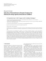
Figure 2: SINR for hexagonal multicarrier system for Δt ∈ [−0.5, 0.5].
Upon substituting the scattering function (20) into (18)
and (19), we have
E
s
Δt, Δ f , τ
rms
, f
d
=
σ
2
c
πτ
rms
f
d
∞
0
e
−τ/τ
rms
e
−(π/σ)(τ−Δt)
2
dτ
f
d
−f
d
e
−σπ(υ+Δ f )
2
1 −
υ/ f
d
)
2
dυ,
E
N
Δt, Δ f , τ
rms
, f
d
=
σ
2
c
πτ
rms
f
d
(m,n)
/
=(0,0)
∞
0
e
−τ/τ
rms
e
−π(mT+τ−Δt)
2
/σ
dτ
×
f
d
−f
d
e
−σπ(nF+υ+Δ f )
2
1 −
υ/ f
d
2
dυ
+
(m,n)
/
=(0,0)
∞
0
e
−τ/τ
rms
e
−π((m+1/2)T+τ−Δt)
2
/σ
dτ
×
f
d
−f
d
e
−σπ((n+1/2)F+υ+Δ f )
2
1−
υ/ f
d
2
dυ
+σ
2
n
A
g
(0, 0)
.
(21)
SINRofreceivedsignalcanbeexpressedas
R
SIN
Δt, Δ f , τ
rms
, f
d
=
E
s
Δt, Δ f , τ
rms
, f
d
E
N
Δt, Δ f , τ
rms
, f
d
. (22)
Plugging (21) into (22), we find
R
SIN
Δt, Δ f , τ
rms
, f
d
=
σ
2
c
πτ
rms
f
d
∞
0
e
−τ/τ
rms
−((π/σ)(τ−Δt)
2
)
dτ
f
d
−f
d
e
−σπ(υ+Δ f )
2
1−
υ/ f
d
2
dυ
·
σ
2
c
πτ
rms
f
d
(m,n)
/
=(0,0)
∞
0
e
−τ/τ
rms
−(π(mT+τ−Δt)
2
/σ)
dτ
×
f
d
−f
d
e
−σπ(nF+υ+Δf)
2
1 −
υ/ f
d
2
dυ
+
(m,n)
/
=(0,0)
∞
0
e
−τ/τ
rms
−(π((m+1/2)T+τ−Δt)
2
/σ)
dτ
×
f
d
−f
d
e
−σπ((n+1/2)F+υ+Δ f )
2
1 −
υ/ f
d
2
dυ
+ σ
2
n
A
g
(0, 0)
−1
.
(23)
Equation (23) indicates that R
SIN
(Δt, Δ f , τ
rms
, f
d
)canbe
modeled as a function of CFO, TO, and channel spread factor
τ
rms
f
d
.
6 EURASIP Journal on Wireless Communications and Networking
3
4
5
6
7
8
9
10
SINR (dB)
−0.50 0.5
Frequency offset
SNR
= 10 dB
HMM τ
rms
f
d
= 0.02
HMM τ
rms
f
d
= 0.01
HMM τ
rms
f
d
= 0.005
OFDM τ
rms
f
d
= 0.02
OFDM τ
rms
f
d
= 0.01
OFDM τ
rms
f
d
= 0.005
4
6
8
10
12
14
16
18
SINR (dB)
−0.500.5
Frequency offset
SNR
= 20 dB
4
6
8
10
12
14
16
18
20
SINR (dB)
−0.500.5
Frequency offset
SNR
= 30 dB
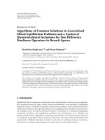
Figure 3: SINR for hexagonal multicarrier system for Δ f ∈ [−0.5, 0.5].
6. Numerical Results and Disscussion
Here, we examine the SINR performance of hexagonal
multicarrier systems over a DD channel. All experiments
employed N
= 80, σ = T/
√
3F hexagonal multicarrier
system, and τ
rms
/f
d
of DD channel is fixed. Obviously,
the hexagonal transmission pattern is fixed while the rms
delay spread and the maximal Doppler spread increase
simultaneously with the increasing of channel spread factor
τ
rms
f
d
. The center carrier frequency is set to f
c
= 5GHz
and the sampling intervals T
s
= 10
−6
s, F = 25 kHz, and
T
= 1 ×10
−4
s. Δt in all simulation results are normalized to
T/2, and Δ f are normalized to F/2.
We fixed Δ f to 0 and the product τ
rms
f
d
to 0.02, 0.01,
and 0.005. We repeat this simulation for a variety of values
SNR in the range of 10 dB
∼30 dB. The result is shown in
Figure 2. We see that the power of the ISI and ICI caused
by TO strongly depends on the channel spread factor of
DD channel. The maximum SINR timing decreases with the
product τ
rms
f
d
increasing, and the timing offset Δt increases
as the product τ
rms
f
d
increases, that is, there is a delay
between the maximum SINR timing and the first tap of
DD channel from the SINR point of view. It can be seen
from Figure 2 that the aforementioned delay increases as
the product τ
rms
f
d
increases. HMM does an excellent job of
maintaining high SINR. CP-OFDM with guard N
g
= N/4
perfectly suppresses ISI caused by TO within cyclic prefix, but
does a poor job of combating the DD channel, and there is
an SINR gap between HMM and CP-OFDM about 4
∼ 7dB
at SNR
= 30 dB.
In Figure 3,wefixedΔt to the maximum SINR timing
and the product τ
rms
f
d
to 0.02, 0.01, and 0.005. It is seen
that the SINR depends on the channel spread factor of
DD channel and the SINR obtains its maximum value at
Δ f . Meanwhile, SINR decreases with the product τ
rms
f
d
increasing. From Figure 3, we see that HMM also does a
good job of ISI/ICI suppression, and there is also an SINR
gap between HMM and CP-OFDM about 4
∼ 8dB at
SNR
= 30 dB and CFO in the range of −0.5 ∼ 0.5. Effects
of both CFO and TO on the SINR performance of hexagonal
multicarrier systems and CP-OFDM systems at SNR
= 30 dB
are shown in Figure 4, τ
rms
f
d
is set to 0.02.
The maximum SINR with the variety of SNR and τ
rms
f
d
is depicted in Figure 5. A lower bound (LB) on the effects
of Doppler spread in SINR performance of OFDM system
[18] is depicted for comparison. It can be seen that there is
a degradation of SINR with the increasing of τ
rms
f
d
.Thereis
about 1 dB SINR loss of HMM system with τ
rms
f
d
from 0.01
to 0.02 while OFDM SINR loss is about 3 dB. HMM system
does a good job of combating DD channel. The degradation
of SINR in CP-OFDM system increases as the channel spread
factor increases.
7. Conclusion
This paper examines the effects of insufficient synchroniza-
tion on the amplitude and phase of the demodulated symbol
by using a projection receiver in hexagonal multicarrier
modulation systems. Furthermore, effects of CFO, TO, and
EURASIP Journal on Wireless Communications and Networking 7
−5
0
5
10
15
20
SINR (dB)
−0.5
−0.25
0
0.25
0.5
Timing offset
−0.5
−0.3
−0.1
0.1
0.3
0.5
Frequency offset
HMM
CP-OFDM
Figure 4: Effects of TO and CFO on SINR for hexagonal
multicarrier system with τ
rms
f
d
= 0.02 at SNR = 30dB.
−10
−5
0
5
10
15
20
SINR (dB)
0 5 10 15 20 25 30 35 40
SNR (dB)
HMM τ
rms
f
d
= 0.02
HMM τ
rms
f
d
= 0.01
HMM τ
rms
f
d
= 0.005
OFDM τ
rms
f
d
= 0.02
OFDM τ
rms
f
d
= 0.01
OFDM τ
rms
f
d
= 0.005
LB[18] τ
rms
f
d
= 0.02
LB[18] τ
rms
f
d
= 0.01
LB[18] τ
rms
f
d
= 0.005
Figure 5: Effects of channel spread factor on SINR for hexagonal
multicarrier system.
channel spread factor on the performance of SINR in hexag-
onal multicarrier modulation systems are further discussed.
The exact SINR expression versus insufficient synchroniza-
tion and channel spread factor is derived. Both theoretical
analysis and simulation results show that similar degradation
on symbol amplitude and phase caused by insufficient syn-
chronization is incurred as in common OFDM transmission:
(1) CFO and TO introduce interference among subcarriers
and symbols; (2) the transmitted symbols experience an
amplitude reduction and a time variant phase shift due to
CFO; (3) the transmitted symbols are attenuated and rotated
by a phasor whose phase is proportional to the subcarrier
index and TO; (4) the SINR of received symbols decreases
as the channel spread factor increases. Our theoretical
analysis is confirmed by numerical simulations, showing that
HMM systems outperform traditional CP-OFDM systems
with respect to SINR against ISI/ICI caused by insufficient
synchronization and doubly dispersive channel.
Acknowledgment
This research was supported by China National Science Fund
under Contract no. 60772083.
References
[1] T. S. Rappaport, A. Annamalai, R. M. Buehrer, and W. H.
Tranter, “Wireless communications: past events and a future
perspective,” IEEE Communications Magazine, vol. 40, no. 5,
pp. 148–161, 2002.
[2] W. Kozek and A. F. Molisch, “Nonorthogonal pulseshapes for
multicarrier communications in doubly dispersive channels,”
IEEE Journal on Selected Areas in Communications, vol. 16, no.
8, pp. 1579–1589, 1998.
[3] D. Schafhuber, G. Matz, and F. Hlawatsch, “Pulse-shaping
OFDM/BFDM systems for time-varying channels: ISI/ICI
analysis, optimal pulse design, and efficient implementa-
tion,” in Proceedings of the 13th IEEE International Sympo-
sium on Personal, Indoor and Mobile Radio Communications
(PIMRC ’02), vol. 3, pp. 1012–1016, Lisbon, Portugal, Septem-
ber 2002.
[4] R. Haas and J C. Belfiore, “A time-frequency well-localized
pulse for multiple carrier transmission,” Wireless Personal
Communications, vol. 5, no. 1, pp. 1–18, 1997.
[5]B.LeFloch,M.Alard,andC.Berrou,“Codedorthogonal
frequency division multiplex [TV broadcasting],” Proceedings
of the IEEE, vol. 83, no. 6, pp. 982–996, 1995.
[6] H. B
¨
olcskei, P. Duhamel, and R. Hleiss, “Design of pulse shap-
ing OFDM/OQAM systems for high data-rate transmission
over wireless channels,” in Proceedings of the IEEE International
Conference on Communications (ICC ’99), vol. 1, pp. 559–564,
Vancouver, Canada, June 1999.
[7] S. Mirabbasi and K. Martin, “Overlapped complex-modulated
transmultiplexer filters with simplified design and superior
stopbands,” IEEE Transactions on Circuits and Systems II, vol.
50, no. 8, pp. 456–469, 2003.
[8] P. Martin, F. Cruz-Roldan, and T. Saramaki, “A windowing
approach for designing critically sampled nearly perfect-
reconstruction cosine-modulated transmultiplexers and filter
banks,” in Proceedings of the 3rd International Symposium on
Image and Signal Processing and Analysis (ISPA ’03), vol. 2, pp.
755–760, Rome, Italy, September 2003.
[9] T. Strohmer and S. Beaver, “Optimal OFDM design for
time-frequency dispersive channels,” IEEE Transactions on
Communications, vol. 51, no. 7, pp. 1111–1122, 2003.
[10] K. Liu, T. Kadous, and A. M. Sayeed, “Orthogonal time-
frequency signaling over doubly dispersive channels,” IEEE
Transactions on Information Theor y, vol. 50, no. 11, pp. 2583–
2603, 2004.
[11] V. Kumbasar and O. Kucur, “ICI reduction in OFDM systems
by using improved sinc power pulse,” DigitalSignalProcessing,
vol. 17, no. 6, pp. 997–1006, 2007.
8 EURASIP Journal on Wireless Communications and Networking
[12] P. Jung and G. Wunder, “The WSSUS pulse design problem in
multicarrier transmission,” IEEE Transactions on Communica-
tions, vol. 55, no. 10, pp. 1918–1928, 2007.
[13] S. Das and P. Schniter, “Max-SINR ISI/ICI-shaping multicar-
rier communication over the doubly dispersive channel,” IEEE
Transactions on Signal Processing, vol. 55, no. 12, pp. 5782–
5795, 2007.
[14] M. Ma, B. Jiao, and W. C. Y. Lee, “A dual-window technique
for enhancing robustness of OFDM against frequency offset,”
IEEE Communications Letters, vol. 12, no. 1, pp. 17–19, 2008.
[15] G. Lin, L. Lundheim, and N. Holte, “Optimal pulses robust
to carrier frequency offset for OFDM/QAM systems,” IEEE
Communications Letters, vol. 12, no. 3, pp. 161–163, 2008.
[16] F M. Han and X D. Zhang, “Hexagonal multicarrier mod-
ulation: a robust transmission scheme for time-frequency
dispersive channels,” IEEE Transactions on Signal Processing,
vol. 55, no. 5, part 1, pp. 1955–1961, 2007.
[17] P. Jung and G. Wunder, “On time-variant distortions in multi-
carrier transmission with application to frequency offsets and
phase noise,” IEEE Transactions on Communications, vol. 53,
no. 9, pp. 1561–1570, 2005.
[18] X. Cai and G. B. Giannakis, “Bounding performance and sup-
pressing intercarrier interference in wireless mobile OFDM,”
IEEE Transactions on Communications, vol. 51, no. 12, pp.
2047–2056, 2003.
[19] J. H. Conway and N. J. A. Sloane, Sphere Packings, Lattices and
Groups, Springer, New York, NY, USA, 2nd edition, 1993.
[20] L. Cohen, Time-Frequency Analysis, Prentice-Hall, Englewood
Cliffs, NJ, USA, 1995.
[21] M. P
¨
atzold, Mobile Fading Channels, John Wiley & Sons, West
Sussex, UK, 2002.