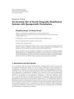
Báo cáo hóa học: " Research Article On the Ability of the 802.11p MAC Method and STDMA to Support Real-Time Vehicle-to-Vehicle Communication" pdf
Bạn đang xem bản rút gọn của tài liệu. Xem và tải ngay bản đầy đủ của tài liệu tại đây (923.38 KB, 13 trang )
Hindawi Publishing Corporation
EURASIP Journal on Wireless Communications and Networking
Volume 2009, Article ID 902414, 13 pages
doi:10.1155/2009/902414
Research Article
On the Ability of the 802.11p MAC Method and STDMA to
Support Real-Time Vehicle-to-Vehicle Communication
Katrin Bilstrup,
1, 2
Elisabeth Uhlemann,
1, 3
Erik G. Str
¨
om,
1, 2
and Urban Bilstrup
1
1
Centre for Research on Embedded Systems, Halmstad University, P.O. Box 823, 301 18 Halmstad, Sweden
2
Department of Signals and Systems, Chalmers University of Technology, 412 96 G
¨
oteborg, Sweden
3
Transport, Information and Communication M 1.6, Volvo Technology Corporation, 405 08 G
¨
oteborg, Sweden
Correspondence should be addressed to Katrin Bilstrup,
Received 1 May 2008; Revised 17 October 2008; Accepted 7 December 2008
Recommended by Onur Altintas
Tr affic safety applications using vehicle-to-vehicle (V2V) communication is an emerging and promising area within the intelligent
transportation systems (ITS) sphere. Many of these new applications require real-time communication with high reliability,
meaning that packets must be successfully delivered before a certain deadline. Applications with early deadlines are expected
to require direct V2V communications, and the only standard currently supporting this is the upcoming IEEE 802.11p, included
in the wireless access in vehicular environment (WAVE) stack. To meet a real-time deadline, timely and predictable access to the
channel is paramount. However, the medium access method used in 802.11p, carrier sense multiple access with collision avoidance
(CSMA/CA), does not guarantee channel access before a finite deadline. In this paper, we analyze the communication requirements
introduced by traffic safety applications, namely, low delay, reliable, real-time communications. We show by simulation of a simple,
but realistic, highway scenario, that vehicles using CSMA/CA can experience unacceptable channel access delays and, therefore,
802.11p does not support real-time communications. In addition, we present a potential remedy for this problem, namely, the use
of self-organizing time division multiple access (STDMA). The real-time properties of STDMA are investigated by means of the
same highway simulation scenario, with promising results.
Copyright © 2009 Katrin Bilstrup et al. This is an open access article distributed under the Creative Commons Attribution License,
which permits unrestricted use, distribution, and reproduction in any medium, provided the original work is properly cited.
1. Introduction
Some of the new, emerging applications for enhancing
traffic safety found within the intelligent transportation
systems (ITS) sphere can be classified as real-time sys-
tems, that is, the transmitted messages have deadlines. In
addition, requirements on high reliability and low delay
are imposed on the wireless communication systems in
use. For example, it is vital that an event-driven message
reaches its intended recipient(s) before a particular time
instant, for example, before a traffic accident. Information
that is delivered correctly, but after the deadline in a real-
time communication system, is not only useless, but can
also have severe consequences for the trafficsafetysystem.
This problem has been pointed out also in [1–3]. In most
cases, the extremely low delays required by trafficsafety
applications imply the need for ad hoc network architectures,
supporting direct vehicle-to-vehicle (V2V) communication
in peer-to-peer mode. The IEEE 802.11p draft standard,
intended for V2V ad hoc communication in high-speed
vehicular environments, has received a lot of attention since
its project authorization request (PAR) was approved by
IEEE [4], which states amongst other things that multiple
data exchanges should be completed within 50 milliseconds
time frames.
The original IEEE 802.11, intended for wireless local area
networking (WLAN), has two well-known drawbacks within
its medium access control (MAC) technique carrier sense
multiple access (CSMA): it can cause unbounded delays
before channel access as well as collisions on the channel.
The MAC protocol decides who has the right to transmit
next on the shared communication channel. In a carrier
sense system, such as CSMA, the node first listens to the
channel and if the channel has been free for a certain time
period, the node transmits directly with the implication that
another node can have conducted the exact same procedure,
2 EURASIP Journal on Wireless Communications and Networking
resulting in a collision on the channel. Moreover, a node can
experience very long channel access delays due to the risk
of the channel being busy during its listening period. These
two phenomena occur primarily during high utilization
periods in the network. CSMA is used by the whole IEEE
802.11 family as well as its wired counterpart IEEE 802.3
Ethernet. One of the reasons for the success of both WLAN
and Ethernet is the straightforward implementation of the
standard resulting in reasonably priced equipment. Due to
this WLANs and Ethernet are often applied to other domains
than they originally were designed for. Even though CSMA
is unsuitable for real-time communication because of the
unbounded channel access delays, Ethernet has paved its
way into the industrial communication scene where many
real-time systems are found. However, the problems with
the MAC method can be solved here by introducing more
network equipment, such as switches and routers, and
thereby reducing the number of nodes competing for the
shared channels, that is, breaking up collision domains. In
the wireless domain, however, there is no such easy solution
since the wireless channel has to be shared by all users.
Further, when the CSMA algorithm is applied in the wireless
domain, an interferer could easily jam a geographical area,
intentionally or unintentionally, and the nodes in this area
would defer their access even though there is no “real” data
traffic present. A wireless carrier sense system is thus more
susceptible to interference since no access will occur as long
as activity is detected on the channel.
The upcoming standard IEEE 802.11p, intended for
vehicular ad hoc networks (VANET), will use CSMA as
its MAC method, despite its inability to support real-time
deadlines. The argument is that the problems with CSMA are
most pronounced at high network loads, and traffic smooth-
ing can be introduced to keep the data traffic at an acceptable
level. However, traffic smoothing is typically used in centrally
controlled networks or networks in restricted geographical
areas. A VANET is neither a restricted geographical area,
nor can it be made predictable by a central controller due
to its highly dynamic characteristics and requirements on
low delay. In addition, traffic smoothing only reduces the
average delay, and the main problem with unbounded worst
case delay remains. A remedy to the problem with potentially
unbounded channel access delays when using CSMA could
be to use a self-organizing time division multiple access
(STDMA), a decentralized, yet predictable, MAC method
with a finite channel access delay, making it suitable for
real-time ad hoc vehicular networks. An STDMA algorithm
is already in commercial use in a system called automatic
identification system (AIS), where it focuses on collision
avoidance between ships.
This paper analyzes the particular communication re-
quirements introduced by traffic safety applications, namely,
low-delay, reliable, real-time communications. The require-
ment on low delay implies the need for an ad hoc V2V net-
work, whereas the reliability constraint poses high demands
on the physical layer in terms of adaptive channel coding
and modulation. The ad hoc network together with the real-
time constraints requires a decentralized predictable MAC
method capable of meeting real-time deadlines. We compare
two MAC methods: CSMA of 802.11p and STDMA of AIS
in terms of channel access delays by means of simulating a
highway scenario. We have selected a data trafficscenario
that is typically found in traffic safety applications: time-
triggered periodic position messages having deadlines such
that they expire when the next updated message arrives.
The predictability in terms of channel access delays and the
distance to concurrent transmitters are evaluated from the
perspective of the sending node.
Related research is presented next in this paper in
Section 2, followed by an introduction to real-time com-
munication systems in Section 3 and the importance of the
MAC method in Section 4. The paper continues with a per-
formance comparison of CSMA and STDMA for real-time
V2V communications by means of computer simulations in
Section 5, followed by our conclusions in Section 6.
2. Related Work
The MAC schemes in the literature that are targeting VANETs
can be divided into two classes: CSMA-based and TDMA-
based. The CSMA-based protocols considered, for example,
in [5, 6] are enhanced by providing different priority levels
allowing packets with higher priorities to have shorter
listening period before a channel access attempt is made.
However, the channel may still be busy and when it is,
a transmitter with higher priority trafficwillrandomizea
shorter backoff time than transmitters with lower priority
traffic. This type of prioritization mechanism where the
delay before channel access together with the backoff time
is manipulated according to packet priorities is also found
in the standard IEEE 802.11e which is included in IEEE
802.11p. In [5], there is also an additional feature where
a potential transmitter sends a busy tone using a reserved
frequency to get the attention from the intended recipient,
which then polls the busy tone sender. However, busy tones
and prioritizing packets do not eliminate the problem and
there is still no upper bound on when channel access can take
place.
The TDMA-based protocols in [7–10] use time slots to
achieve collision-free transmissions of data. The difference
between these protocols lies in how they assign their time
slots. In [7, 8], space division multiplexing (SDM) is used,
where the road is first divided into spaces, and within each
space a TDMA scheme is mapped. Each vehicle will use dif-
ferent time slots depending on where it is currently situated.
This approach is promising but likely to be impractical in a
real system. The overall network utilization will be low since
many time slots are unused when the vehicle trafficissparse.
The authors of [7, 8] do propose algorithms for increasing
the time slot usage, but other problems remain. For example,
a spatial division of each road needs to be set up, possibly
offline. In [9], the 3G radio interface UMTS terrestrial radio
access time division duplex (UTRA TDD) is used as physical
layer (PHY), and at the MAC level, the available time is also
divided into slots. To achieve a transmission opportunity in
the TDMA frame in [9, 10], a random access channel (i.e.,
CSMA) is deployed. The request for time slots during high
EURASIP Journal on Wireless Communications and Networking 3
utilization periods on a contention-based random access
channel will face the same problem as in [5, 6]. Another
drawback with almost all of the above MAC protocols [5, 6,
9, 10] proposed for the vehicular environment is that they do
not incorporate the dynamics of the network and, therefore,
they are still only applicable to slow moving objects and
ordinary ad hoc networks.
The physical layer (PHY) of the upcoming IEEE 802.11p
and its capabilities has been treated in a series of articles
[11–13]. The investigation of the PHY is very important to
increase the transmission reliability, but still if no channel
access is possible, we will never use the PHY facilities.
Enhancements to the MAC layer of 802.11p have been
suggested and evaluated in [14–16], which all have in
common that they want to decrease the data trafficload
by, for example, prioritizing better. An attempt to avoid
packet collisions by using a polling scheme is suggested
in [14]. However, none of these articles clearly points out
the MAC layer to be the weak part of 802.11p in order to
support emerging traffic safety systems with low-delay real-
time requirements. The direct communication enabled by
the ad hoc mode and the prioritization does decrease the
average delay, but the worst case collision scenario is still the
same. In [17], a reliability analysis of the 802.11p is made
from an application and a communication point of view.
No enhancements are suggested, but the 802.11p together
with real-world application data traffic was evaluated and
found to provide sufficient reliability. However, the real-
world data was collected when three vehicles in a highway
scenario were communicating, which has to be regarded
as a very lightly loaded system. In such a scenario with
few competing nodes, almost any type of MAC method
will function satisfactory. A more realistic setting with
more communicating nodes is likely to stress the MAC
method further. An analytical performance evaluation of
802.11p together with simulations is presented in [18]. It is
concluded that 802.11p cannot ensure time-critical message
dissemination and that the solution ought to be a reduction
in the number of high priority messages.
3. Real-Time Communication
Real-time communication implies that the communication
task has demands on timely delivery, that is, messages should
reach their intended recipients before a certain deadline
in time and with a certain reliability (error probability).
Communicating real-time messages does not necessarily
require a high transmission rate or a low delay, but it
does require a predictable behavior such that the message
is delivered before the deadline with the requested error
probability. Therefore, real-time communication tasks are
characterized by two important parameters: deadline and
reliability [19]. Depending on the application, a missed
deadline could potentially have severe consequences for the
system user or simply lead to temporarily performance
degradation. Emerging traffic safety systems based on vehic-
ular communication are real-time systems in accordance
with the above classification. Examples of real-time deadlines
within traffic safety applications are lane-change warnings,
rear-end collision warnings, and conveying slippery road
conditions, all of which include messages which must reach
the intended recipients before the event takes place.
A Voice over IP (VoIP) conversation over the Internet
is an example of a real-time system that has data packets
with deadlines since it is better to drop VoIP packets that are
late than to introduce longer and longer delays. The antilock
braking system (ABS) in a vehicle is another example of a
real-time system; but contrary to the VoIP application, the
requirement on error probability is significantly higher in
this control application and also packets delivered shortly
after the deadline could be used with diminishing returns.
Consequently, applications have different requirements on
the values of the parameters deadline and reliability,for
example, a VoIP conversation can tolerate packet losses,
implying relaxed constraints on reliability, but puts stringent
demands on keeping the deadlines and in the ABS case
it is almost the other way around. Vehicle safety systems,
communicating to avoid or mitigate traffic accidents, are
real-time systems where it is equally important that the
packet loss rate is close to zero (high reliability) as it is to keep
the deadlines. One way to improve the ability of the real-time
communication system to meet deadlines is to prioritize the
data traffictoprovideclassesofdifferent importances, but
obviously if all nodes in the network have traffic from the
same priority class to transmit this will not have any effect.
Real-time communication systems are a mature research
area within, for example, wired industrial networks and
there exists a plethora of standards intended for real-time
communication in industrial environments, for example,
fieldbuses [2] or control networks [20], often with its own
manufacturer. Since the industrial communication society
has not agreed upon one common network technology,
the local area network (LAN) standard Ethernet has won
terrain due to its affordable equipment and the literature
about the use of Ethernet in industrial environments is
vast, for example, [21–23]. An attempt to make Ethernet
predictable and more suitable for real-time traffic is RETHER
[21], where a token ring-based protocol is used on top
of the normal CSMA protocol. Despite the MAC method
being CSMA, Ethernet can be used in industrial real-time
applications due to the following reasons: (i) an industrial
network is a controlled environment where the number of
network members is known in advance, (ii) the controlled
environment also implies that the data traffic including
priorities is known or can be determined in the worst
case, and (iii) the communication takes place via a wire
implying significantly lower bit error rates than for wireless
communication. These three things help the designer to
either keep the network load low such that we are not
operating close to what the network can handle or to
introduce real-time enhancements to CSMA possible in
stationary networks, such as token ring.
One of the most important parts of a real-time commu-
nication system is the MAC method. In this paper, we are
investigating the ability of a sending node to get access to the
channel within a finite upper bound. Therefore, we define
the MAC channel access delay as the time it takes from when
4 EURASIP Journal on Wireless Communications and Networking
a packet arrives to the MAC from the layer above it, until
the packet is delivered to the PHY layer for transmission. For
brevity, we also denote the MAC channel access delay by T
acc
.
An MAC method is defined to be deterministic if the worst
case MAC channel access delay is finite. A nondeterministic
MAC method (i.e., an MAC method for which T
acc
is
not finite) is unsuitable for real-time data traffic having
deadlines. The set of deterministic MAC methods includes
master-slave schemes, token passing schemes, TDMA, fre-
quency division multiple access (FDMA), and code division
multiple access (CDMA). These methods are well suited
for real-time data traffic but they typically require a central
coordinator that can distribute channel resources among the
users (i.e., allot time slots/frequency bands/spreading codes).
CSMA, on the other hand, is easily deployed in decentralized,
ad hoc networks but is also nondeterministic. VANET is
a special case of ad hoc networks and is characterized by
the fact that the nodes constituting the VANET are highly
mobile and can reach very high speeds. This mobility has a
great impact on the choice of MAC scheme, since it must be
designed to cope with rapid changes in the network topology,
where communication links constantly form and break. The
problem with VANETs is threefold; (i) it is hard to foresee the
number of members of the network, (ii) it is hard to predict
the amount of data traffic generated by the nodes, that is,
the aggregated bandwidth, and (iii) the wireless channel is
stochastic and time-varying in its nature and influenced by
many parameters. In a static wireless ad hoc network, (i) and
(ii) could be controlled but (iii) remains a challenge. Coding
and diversity schemes play a vital role to increase the data
reliability and mitigate the effects of fading and interference
of the channel, but before these techniques can be applied,
a transmission must take place, that is, the node must get
access to the channel.
4. The 802.11p and STDMA MAC Methods
In this paper, we analyze the real-time properties of two MAC
methods: CSMA of 802.11p and STDMA of AIS. Since CSMA
is nondeterministic, we are interested in knowing how it is
affected by the network load, that is, how many deadlines
are missed when the network load increases? STDMA, on the
other hand, being deterministic, we are interested in knowing
any potential drawbacks such as increased interference. This
section describes the functionality of the two MAC methods.
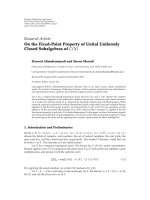
4.1. The MAC method of 802.11p. Wireless access in vehicular
environment (WAVE) is the protocol stack concept for the
vehicular environment developed by IEEE. It contains an
MAC and PHY layer derived from IEEE 802.11 [24], a new
transport/network layer protocol (IEEE 1609.3), security
issues specified in 1609.2, and an application protocol
called 1609.1. The MAC method of the upcoming standard
IEEE 802.11p is a CSMA/CA derived from the 802.11,
and 802.11p will also use the quality-of-service (QoS)
amendment 802.11e, Figure 1. The PHY layer of 802.11p
is the 802.11a, based on orthogonal frequency division
multiplexing (OFDM), with some minor changes to fit the
high-speed vehicular environment. The 802.11p together
with the 1609.4 standard is designed for 10 MHz wide
channels instead of 20 MHz as it is in the original 802.11a.
Due to this, the transfer rates will be halved in 802.11p
compared to 802.11a, implying transfer rates of 3, 4.5, 6,
9, 12, 18, 24, and 27 Mbps. The different transfer rates are
obtained through changing modulation scheme and channel
code rate. Another big difference in the 802.11p compared to
the original 802.11 is that there is no difference between the
nodes in the network, that is, all nodes are peers including
the roadside units. There exists no access point functionality
in 802.11p even though the vehicular network will contain
roadside units at certain spots.
IEEE 802.11p will use enhanced distributed channel
access (EDCA) from the QoS amendment IEEE 802.11e [25]
as MAC method, which is an enhanced version of the basic
distributed coordination function (DCF) found in 802.11.
The DCF is based on CSMA/CA, meaning that the station
starts by listening to the channel, and if it is free for a
time period called an arbitration interframe space (AIFS),
the sender can start transmitting directly. If the channel is
busy or becomes occupied during the AIFS, the station must
perform a backoff, that is, the node has to defer its access
according to a randomized time period. In 802.11p, QoS is
obtained by putting the data traffic within each node into
four different priority queues. These queues have different
AIFS and backoff parameters, that is, the higher priority,
the shorter AIFS. The backoff procedure in 802.11 works
as follows: (i) draw an integer from a uniform distribution
[0, CW], where CW refers to the current contention window,
(ii) multiply this integer with the slot time derived from
the PHY layer in use, and set this as the backoff value, (iii)
decrease the backoff value only when the channel is free, (iv)
upon reaching a backoff value of 0, send immediately. The
MAC protocol of 802.11 is a stop-and-wait protocol and the
sender will wait for an acknowledgment (ACK). If no ACK is
received by the sender for some reason (that the transmitted
packet never reached the recipient, the packet was incorrect
at reception, or the ACK never reached the sender), a backoff
procedure must also be invoked. For every attempt to send a
specific packet, the size of the contention window, CW,will
be doubled from its initial value (CW
min
) until it reaches a
maximum value (CW
max
). This is done since during high
utilization periods, it is convenient to distribute the nodes
that want to send over a longer time period. After a successful
transmission or when the packet had to be thrown away
because the maximum number of channel access attempts
was reached, the contention window will be set to its initial
value again. In Table 1, default parameter settings for the
different queues in 802.11p are found together with the
CW setting. In a broadcast situation, the receiving nodes
will not send ACKs. Therefore, a sender never knows if
anyone has received the transmitted packet correctly or not.
Due to this, the sender will perform at most one backoff,
which occurs when the initial channel access attempt senses a
busy channel. Hence, broadcast packets will never experience
multiple backoffs, and the contention window will always be
CW
min
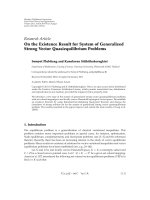
.InFigure 2(a), a flow diagram presents the CSMA
procedure in the broadcast situation with periodic traffic.
EURASIP Journal on Wireless Communications and Networking 5
Medium access control (MAC)
802.11e QoS
FHSS
2.4GHz
1–2 Mbps
DSSS
2.4GHz
1–2 Mbps
IR
1–2 Mbps
OFDM
5GHz
6–54 Mbps
802.11a
DSSS/HR
2.4GHz
1–11 Mbps
802.11b
DSSS/
CCK/OFDM/
PBCC
2.4GHz
1–54 Mbps
802.11g
Parts that 802.11p uses
Physical
layers
Figure 1: An overview of the WLAN family 802.11, showing in bold which parts that 802.11p will use and modify.
Table 1: Default parameter settings in 802.11p for the different
queues.
Queue no. 1 Queue no. 2 Queue no. 3 Queue no. 4
Priority Highest −→ Lowest
AIFS 34 μs34μs43μs79μs
CW
start
3 7 15 15
CW
end
511 1023 1023 1023
4.2. Self-Organizing TDMA. The STDMA algorithm pre-
sented herein is found in a standard for the shipping
industry, automatic identification system (AIS) [26]. There
are international regulations saying that ships larger than 300
grosstonmustuseAIS,whichisatranspondertechnique.
Every ship will transmit messages containing information
about its position, heading, and so on, at a predetermined
heartbeat rate. The AIS system is used for identifying ships
in the vicinity and it is of great help in, for example, bad
weather situation since false radar images are a problem.
With AIS, the ship will build its own surveillance picture
about the neighborhood using the messages received from
other ships. Ships all over the world can meet and track
each other through this system. AIS divides the time
into one minute frames where each frame contains 2250
time slots and a transfer rate of 9.6 kbps is supported.
Two different frequency channels, 161 MHz and 162 MHz,
are used for communication and the ships will divide its
messages between these two channels (called channel A and
channel B). A message is 256 bits long and it fits into one
time slot.
STDMA [26] is a decentralized scheme where the
network members themselves are responsible for sharing
the communication channel and due to the decentralized
network topology, the synchronization among the nodes is
done through a global navigation satellite system such as GPS
or Galileo. The algorithm is dependent on that all nodes in
the network regularly send messages containing information
about their own position. The STDMA algorithm will use
this position information when choosing slots in the frame.
All network members start by determining a report rate, that
is, deciding the number of position messages that will be sent
during one frame and this translates into the number of slots
required in ditto. When a node is turned on, four different
phases will follow: initialization, network entry, first frame,
and continuous operation. During the initialization, the node
will listen for the channel activity during one frame to
determine the slot assignments, that is, listen to the position
messages sent in each slot. In the network entry phase, the
station determines its own slots to use for transmission
of position messages within each frame according to the
following rules: (i) calculate a nominal increment, NI, by
dividing the number of time slots with the report rate, (ii)
randomly select a nominal start slot (NSS) drawn from the
current slot up to the NI, (iii) determine a selection interval
(SI) of slots as 20% of the NI and put this around the NSS
according to Figure 3, (iv) now the first actual transmission
slot is determined by picking a slot randomly within SI that
is not currently occupied by someone else and this will be
the nominal transmission slot (NTS). If all slots within the SI
are occupied, the slot used by a station located furthest away
from oneself will be chosen. Upon reaching the first chosen
NTS, the station will enter the first frame phase where the
rest of the report rate decided transmission slots (NTSs) are
determined (e.g., a report rate of 10 messages/frame implies
10 NTSs). An NI is added to the NSS and a new SI area is
made available to choose a slot from. This is repeated until
a frame has elapsed and all position messages are assigned a
transmission slot, Figure 3. Every node has only one NSS and
this is used to keep track of when the frame starts for this
particular node, that is, all nodes keep track of its own frame
andtheylookatitasaringbuffer with no start and no end.
Modulo operations are used to avoid static numbering of
slots. The parameters NSS, NS, SI, and NI are kept constant
as long as the node is up running. However, if the report rate
is changed during operation (increased or decreased number
of position messages in the frame for some reason) then the
parameters will be changed since NI is dependent on the
report rate.
When all slots within one frame duration are selected, the
station will enter the continuous operation phase, using the
NTSs decided during the first frame phase for transmission.
During the first frame phase, the node will draw a random
integer n
∈{3, ,8} foreachNTS.AftertheNTShasbeen
used for the n frames, a new NTS will be allocated in the
same SI as the original NTS. This procedure of changing slots
after a certain number of frames is done to cater for network
changes, that is, two nodes that use the same NTS which were
6 EURASIP Journal on Wireless Communications and Networking
CSMA/CA
Listen AIFS
Randomize
backoff
No
Listen AIFS
after channel
has been busy
Channel idle?
Decrement
backoff
Next packet
arrived?
Transmit
Current packet
is thrown, i.e.,
packet drop
Channel idle?
Yes
Next packet
arrived?
No
No
No
Yes
Yes
Yes
No
Yes
Backoff > 0?
(a)
STDMA
Draw a new slot
from the SI
where this slot
is found
Slot counter,
Choose
a new
slot
within
SI
All slots
occupied
within SI?
Choose the slot
in the SI used
by the furthest
away node
Slot counter;
draw a random
integer
announce this
new slot in the
current slot
My own
transmission
slot?
Listen
Slot
occupied?
Transmit
Continuous
operation phase
No
Yes
Yes
Yes
No
No
No
Yes
n ∈{3, ,8},
n>0?
(b)
Figure 2: The two MAC procedures examined in this paper using a data traffic model with broadcasted time-driven messages at
predetermined heartbeat rates, (a) the CSMA procedure according to 802.11p and (b) continuous operation phase of STDMA.
SI SI SI
NSS NS NS
NI NI
NTS
NTS
NTS
··· ···
Figure 3: The frame structure for one node. The NSS and NSs are
equally spaced with an interval of size NI. The SI parameter is also
fixed.
not in radio range of each other when the NTS was chosen
could now have come closer and will then interfere if the NTS
allocation was not changed. In Figure 2(b), the continuous
operation phase of STDMA is depicted.
5. Simulator
The aim of this simulator is to analyze the real-time
properties of the MAC protocols described in Section 4
and especially their behavior in a typical highway scenario,
Figure 4. Due to the real-time properties of the system,
the interesting issue here is how the two MAC methods
will influence the capability of each sending node to timely
deliver data packets, that is, meeting real-time deadlines.
Note that we are dealing with an uncontrolled network since
the number of network nodes cannot be determined in
advance as we are considering vehicles controlled by humans.
On the highway, the highest relative speeds are found and
this causes the network topology to change often and more
rapidly. If a traffic accident occurs, many vehicles could
quickly be gathered in a small geographic area implying
troubles with access to the shared wireless communication
EURASIP Journal on Wireless Communications and Networking 7
channel for individual nodes. As we are studying the MAC
channel access delay for time-driven position messages, we are
not considering the reception of messages at the nodes at this
time.
A promising emerging application within ITS is a
cooperative awareness system such as the AIS for the ships,
where the vehicles will exchange position messages with each
other to build up a map of its surrounding and use this
for different trafficsafetyandefficiency applications. In the
European project SAFESPOT [27], applications that are built
on this kind of message exchange are developed. Routing
in highly mobile networks is also dependent on positions
(i.e., geographical routing) rather than specific addresses
when trying to find ways through the network. Therefore,
time-driven position messages are likely to be of uttermost
importance in future vehicular networks. Consequently,
we have chosen to use broadcasted, time-driven position
messages (the so-called heartbeat messages) as the data traffic
model in the simulator. All vehicles broadcast data packets
at two different heartbeat rates, 5Hz and 10 Hz. There is no
other data traffic in addition to the heartbeat messages. The
highway is 10 000 meter long and contains 5 lanes in each
direction, Figure 4. The vehicles are entering each lane of
the highway according to the Poisson process with a mean
interarrival time of 3 seconds (the 3 seconds are chosen in
accordance with the Swedish 3-second rule, where vehicles
should maintain a 3-second space to the vehicle in front).
The speed of each vehicle is modeled as a Gaussian random
variable with different mean values for each lane, 23 m/s
(
∼83 km/h), 30m/s (∼108 km/h), and 37 m/s (∼133 km/h),
and a standard deviation of 1 m/s. The different speeds
are chosen with the speed regulations of Sweden in mind.
The vehicles will have the same speed as long as they are
staying on the highway and the vehicles do not overtake.
The purpose of this simplistic mobility model is to achieve
a realistic density of vehicles on the highway to test the
communication system. It is of limited interest to use a
more advanced mobility model since we are not studying
applications such as lane change warning or merge assistance
here. Moreover, there is no universally prevailing mobility
model, and the required level of accuracy for the mobility
of vehicular networks is not yet clear [28].
The channel model is a simple circular sensing range
model, Figure 4, in which every node within the sensing area
receives the message perfectly (i.e., without errors). Note that
nodes could be exposed to two concurrent transmissions,
Figure 4, where transmitters TX
1
and TX
2
are sending at
the same time since the transmitters cannot hear each
other: The receivers RX
1
,RX
2
,andRX
3
in Figure 4 will
then experience collisions of the two ongoing transmissions,
unless some sort of power control or multiuser detection
is used. However, since the focus of this simulation is to
characterize the MAC channel access delay, T
acc
,problems
such as exposed and hidden terminals are not addressed
here. As soon as the nodes enter the highway, they will
start to transmit after an initial random delay of between
0 and 100 milliseconds. The simulation has been carried
out with three different packet lengths: N
= 100, 300, and
500 bytes and two different sensing ranges: 500 and 1000
Table 2: Simulation parameters settings for CSMA and STDMA.
Parameter Value
Slot time, T
slot
9 μs
SIFS, T
SIFS
16 μs
AIFS for voice, T
AIFS
34 μs
CW
min
3
CW
max
Will never be used due to broadcast
Backoff time, T
backoff
0, 9, 18, 27 μs
Tr an sfe r r a te, R 3Mbps
Packet sizes, N 100, 300, 500 bytes
Sensing ranges 500, 1000 meters
No. of lanes 2
×5
meters. The sensing range of 1000 meters was chosen because
the PAR of 802.11p [4] states that communication ranges
of up to 1000 meters must be supported and the different
packet lengths are chosen because of the security issues. It
is very important that heartbeat messages can be trusted
since many traffic safety applications will be depending on
these. One way to handle the security issue is to use a
digital signature being approximately 125 bytes [29] and in
worst case this signature must be included in every packet.
Therefore, 500 byte packets should be the worst case length of
heartbeat packets including a signature of 125 bytes, together
with the header, trailer, and position data.
In our CSMA simulations, all vehicles use the MAC
method of 802.11p as described above, and hence each
vehicle must listen before sending and backoff if the channel
is busy or becomes busy during the AIFS. As explained in
Section 4.1, a broadcast packet will experience at most one
backoff procedure due to the lack of ACKs in a broadcast
system. The contention window will never be doubled since
at most one failed channel access attempt can occur. In
Ta bl e 2, parameters used in the simulation of 802.11p are
listed. Since all data traffic in our simulation scenario has
the same priority, only the highest priority AIFS and CW
min
have been used (Tables 1 and 2) and therefore all transmitters
will have the same T
AIFS
value (34 microseconds). The
backoff time is the product of the slot time, T
slot
,anda
random integer uniformly distributed in the interval [0, 3]
implying four possible backoff times, T
backoff
:0,9,18,and
27 microseconds, respectively. In Figure 2(a), a flow diagram
presents the CSMA procedure in the broadcast situation
with periodic position messages from every node. The “Next
packet arrived?” box tests if the new position message has
arrived from the layer above the MAC layer, in which case
the old packet awaiting channel access is outdated and will
be dropped.
The STDMA algorithm found in AIS cannot be used
right away since the dynamics of a vehicular network and a
shipping network are quite different. Further, the AIS system
is using lower frequencies for transmission to reach further
away and the ships need to know much further ahead about
ships in the vicinity to take the right decisions early on. There
is a natural inertia inherent in a shipping system that is not
present in the vehicular environment, that is, braking a truck
8 EURASIP Journal on Wireless Communications and Networking
TX
1
RX
1
TX
2
RX
2
RX
3
37 m/s
30 m/s
30 m/s
23 m/s
23 m/s
37 m/s
30 m/s
30 m/s
23 m/s
23 m/s
Figure 4: Simulation setup.
0
0.2
0.4
0.6
0.8
1
CDF for channel access delay
0 20 40 60 80 100
Channel access delay (ms)
Best case
Average
Wor st ca se
Sensing range
= 500 m
(a)
0
0.2
0.4
0.6
0.8
1
CDF for channel access delay
0 20 40 60 80 100
Channel access delay (ms)
Best case
Average
Wor st ca se
Sensing range
= 1000 m
Missed deadline ratio
=
packet drop probability
(b)
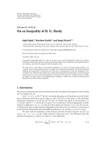
Figure 5: Cumulative distribution function of channel access delay, in a highway scenario with 10 lanes, 500 byte packets, 10 Hz heartbeat.
(a) Sensing range of 500 meters and (b) sensing range of 1000 meters.
and turning a ship in an emergency situation are two very
different tasks. For the most part, we have much shorter
time frames to work with in the vehicular environment. Both
MAC protocols used in the simulation are assumed to use
the same physical layer from 802.11p. The frame duration,
T
frame
, in our simulated STDMA scheme has been set to 1
second and the number of slots is changed inside the frame to
cater for different packet lengths. A transfer rate, R,of3Mbps
has been used and this rate is available with the PHY layer of
802.11p, which has support for eight transfer rates in total
where 3 Mbps is the lowest. This choice is made since the
system under consideration requires high reliability rather
than high throughput, and the lowest transfer rate has the
most robust modulation and coding scheme.
In the STDMA simulations, the vehicles will go through
three phases: initialization, network entry,andfirst frame,
before it ends up in the continuous operation.Thephases
are described in Section 4.2, and in Figure 2(b) the contin-
uous operation phase is depicted. The vehicle stays in the
continuous phase after it has been through the other three.
STDMA always guarantees channel access even when all slots
are occupied within an SI, in which case a slot belonging to
the node located furthest away will be selected.
Unless otherwise stated, the time parameters involved
in the simulation are selected from the PHY specification
of 802.11p. The CSMA transmission time, T
CSMA
, consists
of an AIFS period (listening), T
AIFS
, of 34 microseconds, a
20 microseconds preamble, T
preamble
, and the actual packet
EURASIP Journal on Wireless Communications and Networking 9
0.4
0.6
0.8
1
CDF for number of consecutive dropped packets
510152025
Number of consecutive dropped packets
Sensing range
= 500 m
Sensing range
= 1000 m
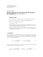
Figure 6: Number of consecutive dropped packets due to no
channel access.
0
0.2
0.4
0.6
0.8
1
CDF for channel access delay in STDMA
SI
lower
× T
STDMA
NS SI
upper
× T
STDMA
Channel access delay (μs)
Figure 7: The CDF for channel access delay when using STDMA.
transmission, T
packet
. The STDMA transmission time,
T
STDMA
, which is the same as the slot time, consists of two
guard times, T
GT
, of 3 microseconds each, T
preamble
, T
packet
,
and two SIFS periods, T
SIFS
, of 16 microseconds each derived
from the PHY layer in use. SIFS stands for short interframe
space and accounts for the transceiver to switch from sending
to receiving state (and vice versa) plus the MAC processing
delay. The total transmission time for CSMA is
T
CSMA
= T
AIFS
+ T
preamble
+ T
packet
(1)
and the total transmission time for STDMA is
T
STDMA
= 2T
GT
+2T
SIFS
+ T
preamble
+ T
packet
. (2)
In Ta bl e 3, the different timing parameters are shown for
different packet lengths.
We assume that all vehicles in the system are perfectly
synchronized with each other in both MAC scenarios and
that in the STDMA case they are also aware of when the
frame starts and how many time slots it contains.
6. Results
The simulated highway scenario described earlier has a
vehicle density of approximately one vehicle every 100 meters
in each lane. The vehicle density is chosen to examine the
scaling performance of the two MAC layers considered in
this paper. The vehicular environment is uncontrolled in
terms of node density and the scalability issue, hence plays
an important role when designing an MAC protocol for
VANETs. Computer simulations have been carried out in
MATLAB with the parameter settings in Tables 2 and 3, yield-
ing 12 different scenarios (all combinations of three packet
lengths, two sensing ranges, and two heartbeat frequencies).
The most demanding case is, of course, when 500 bytes long
packets are sent 10 times per second and the nodes have
a sensing range of 1000 meters, since this corresponds to
the largest aggregated bandwidth requirements per unit area.
In this situation, an ideal MAC method (that schedules all
transmissions perfectly) can handle 70 nodes that are in
radio range of each other without packet collisions. However,
the simulation contains situations that are overloaded and a
node has around 210 neighbors within radio range when the
range is 1000 meters, and consequently, we have to accept
some packet drops by the transmitter or packet collisions in
the air (that might also lead to packet drops at the receiver
side). A packet drop at the transmitter occurs when a new
position message has arrived from the layer above the MAC
layer, before the old packet awaiting channel access has been
transmitted.
Cumulative distribution functions (CDFs) for the chan-
nel access delay, that is, F
T
acc
(x) Pr{T
acc
<x},forCSMA
are shown in Figures 5(a) and 5(b) for two different sensing
ranges, respectively. To avoid edge effects in the simulation,
statistics were only collected from the middle part of the
highway and only when the highway is filled with vehicle
traffic. Dropped packets are considered to have infinite
channel access delays, and the CDFs will, therefore, not reach
unity at a finite delay. We can interpret F
T
acc
(1/f
h
), where f
h
is the heartbeat frequency, as the packet drop probability or,
equivalently, as the missed deadline ratio (since 1/f
h
is the
deadline). The three plots in each figure represents the CDF
for the node performance in the best, worst, average cases.
For a sensing range of 500 meters, approximately 100 nodes
are within radio range and packet drops are unavoidable.
The best case node will drop 5% of its generated packets
and the worst case node will drop 65% of its packets. When
the sensing range is extended to 1000 meters in Figure 5(b),
the situation becomes untenable and, on average, nodes will
drop around 50% of their packets.
The average missed deadline ratios, average over all
vehicles and all messages, for all simulated scenarios using
CSMA are shown in Tabl e 4 . Hence, for a sensing range of
1000 meters and a heartbeat frequency of 10 Hz, only 47% of
the packets are transmitted.
10 EURASIP Journal on Wireless Communications and Networking
0
0.1
0.2
0.3
0.4
0.5
0.6
0.7
0.8
0.9
1
CDF for the distance
0 100 200 300 400 500 600 700 800 900 1000
Minimum distance between two nodes utilizing the same slot (m)
500 byte
300 byte
100 byte
STDMA
(a)
0
0.1
0.2
0.3
0.4
0.5
0.6
0.7
0.8
0.9
1
CDF for the distance
0 100 200 300 400 500 600 700 800 900 1000
Minimum distance between two nodes sending at the same time (m)
500 byte
300 byte
100 byte
CSMA/CA
(b)
Figure 8: The CDF of the minimum distance between two nodes (a) utilizing the same time slot in STDMA and (b) sending at the same
time in CSMA/CA, using 500 byte packets, heartbeat of 10 Hz, sensing range of 1000 m.
Table 3: The transmission times for CSMA and STDMA, respectively, together with packet sizes and number of slots per frame in STDMA.
Packet length N (byte) T
packet
(μs) T
CSMA
(μs) T
STDMA
(μs) No. of slots
100 267 321 325 3076
300 800 854 858 1165
500 1333 1387 1391 718
The distribution of packet errors over time for a certain
node is also of interest. Clearly, it is undesirable to lose many
consecutive packets since this will make the node invisible to
the surrounding vehicles for a period of time. The CDF for
the number of consecutive packet drops is shown in Figure 6
for two different sensing ranges. In the worst case, a node
experienced over 100 consecutive packet drops, implying
invisibility for over 10 seconds. However, in more than 90%
of the cases, fewer than 5 consecutive packets were dropped.
The STDMA algorithm always grants packets channel
access since slots are reused if all slots are currently occupied
within the selection interval of a node. When a node is forced
to reuse a slot, it will choose the slot that is used by a node
located furthest away. Hence, there will be no packet drops at
the sending side when using STDMA and the channel access
delay is always bounded and relatively small. In Figure 7, the
CDF for the channel access delay for STDMA is depicted and
as can be seen, all nodes will choose a slot for transmission
during their selection interval. Therefore, the CDF for T
acc
in STDMA is ending at unity after a finite delay as compared
to the CDF for T
acc
in CSMA according to Figures 5(a) and
5(b).
This finite upper bound on T
acc
in STDMA does,
however, come at the expense of increased interference on the
channel (i.e., more packet collisions in the air will occur) as
compared with CSMA. The intentional slot reuse probability
is a parameter that can be used to indicate the interference
level and thereby the reception performance of an STDMA
system. In Tab le 5 , the intentional slot reuse probability is
tabulated for the different data traffic settings. The worst
case is found when the nodes are transmitting 500 bytes long
packets having a heartbeat of 10 Hz and a sensing range of
1000 meters, and then 50% of the slots are intentionally
reused.
In Figure 8(a), the CDF for the minimum distance
between nodes intentionally utilizing the same slot within
sensing range is depicted for different packet lengths. With
asmallerpacketsize,morenodescanbehandledby
the network since smaller packets imply that every node
keeps the channel occupied during a shorter time period.
When long packets are used, the distance between two
nodes intentionally reusing the same slot is reduced. In the
CSMA/CA case, all channel requests did not make it to a
channel access and then the nodes started to drop packets.
However, in the CSMA/CA case when a node gets a channel
access, there is always a risk that someone else sends at the
same time, that is, a collision in the air. This is due to the
fact that nodes can experience the channel idle at the same
time, either because the channel actually is idle or because
ongoing transmissions are not detected (see Figure 2). In
EURASIP Journal on Wireless Communications and Networking 11
Table 4: Probability of packets drop averaged over nodes in a network using CSMA.
CSMA
Sensing range
500 meters 1000 meters
5 Hz 10 Hz 5 Hz 10 Hz
Packet length
100 bytes 0% 0% 0% 0%
300 bytes 0% 0% 0% 35%
500 bytes 0% 22% 33% 53%
Table 5: The intentional reuse of slots within sensing range for different data traffic scenarios in the STDMA case.
STDMA
Sensing range
500 meters 1000 meters
5 Hz 10 Hz 5 Hz 10 Hz
Packet length
100 bytes 0% 0% 0% 0%
300 bytes 0% 0% 0% 34%
500 bytes 0% 22% 15% 50%
Figure 8(b), the CDF for the minimum distance between two
nodes in the CSMA/CA scenario sending at the same time
for three different packet lengths is depicted. The minimum
distance can be interpreted as the distance between the
nodes whose packets will, on the average, interfere the
most with each other. In the 500 bytes, 1000 meters sensing
range scenario, about 47% of the channel requests were
granted (see Tab l e 4), and, from Figure 8(b),weconclude
that the transmitted packets will be interfered by another
transmission within 500 meters in approximately 53% of the
cases.
7. Conclusions
The new emerging cooperative trafficsafetysystemscanbe
classified as real-time communication systems, and they are
characterized by two important parameters: deadline and
reliability (error probability). At the PHY layer, the reliability
could be increased by using tailored channel coding and
diversity techniques to overcome the impairments of the
wireless channel, but first and foremost a timely channel
access must be granted. Otherwise, the PHY layer techniques
are irrelevant. To meet real-time deadlines, the MAC scheme
must be predictable so that it can provide some sort of finite
channel access delay, T
acc
, to guarantee that communication
tasks meet their deadlines, that is, the MAC scheme must be
deterministic (T
acc
is finite).
The upcoming standard IEEE 802.11p intended for
VANET used for safety traffic applications with real-time
communication demands will use CSMA as its MAC method
despite its two well-known drawbacks: unbounded channel
access delays as well as collisions on the wireless channel.
When the node density increases, CSMA has huge troubles
with solving all channel access requests into channel access.
We have proposed to use STDMA as a remedy to the CSMA
scaling problems. STDMA is a decentralized, predictable
MAC method with a finite channel access delay, making it
suitable for real-time ad hoc vehicular networks. An STDMA
algorithm is already in commercial use in a system called
automatic identification system (AIS) where it focuses on
collision avoidance between ships.
We have analyzed the particular communication require-
ments introduced by traffic safety applications, namely, low-
delay, reliable, real-time communications. The requirement
on low delay favors the use of an ad hoc V2V network,
whereas the reliability constraint poses high demands on
the physical layer in terms of adaptive channel coding
and modulation. The ad hoc network together with the
real-time constraints requires a decentralized predictable
MAC method capable of meeting real-time deadlines. We
have, therefore, compared the real-time properties of two
decentralized MAC methods, CSMA of 802.11p and STDMA
of AIS, in terms of channel access delays and interference
(due to packet collisions in the air), by simulating a
highway scenario with periodic broadcast traffic, where the
packets contain information about the sending node, such as
position and speed. The deadline in this case is simply the
time between consecutive packets.
As an example, the results revealed that on a 10-lane
highway where nodes send 500 bytes long packets every 100
milliseconds and the sensing range is 1000 meters, a node
with the CSMA MAC layer can drop up to 80% of the packets
in the worst case (i.e., channel access was not granted during
the 100 milliseconds between two consecutive packets).
Moreover, in this scenario, a vehicle can experience up to 100
consecutive heartbeat packet drops, implying that the vehicle
will become invisible to the surrounding nodes during as
long as 10 seconds. The STDMA algorithm, on the other
hand, always grants packets channel access since slots are
reused if all slots are currently occupied within the selection
interval of a node. When a node is forced to reuse a slot, it
will choose the slot that is used by a node located further
away. Hence, there will be no packet drops at the sending side
when using STDMA and the channel access delay is always
bounded and relatively small.
Packet collisions in the air will occur in both CSMA
(unintentionally) and STDMA networks (intentionally and
12 EURASIP Journal on Wireless Communications and Networking
unintentionally). We have shown that small distances
between the closest interfering nodes are more probable for
CSMA compared to STDMA, indicating, somewhat counter-
intuitively, that the packet collision problem is actually worse
in CSMA compared to STDMA.
Acknowledgment
This work was funded in part by the Knowledge Foundation,
/>References
[1] J. J. Blum, A. Eskandarian, and L. J. Huffman, “Challenges of
intervehicle ad hoc networks,” IEEE Transactions on Intelligent
Transportation Systems, vol. 5, no. 4, pp. 347–351, 2004.
[2] K. Bilstrup, E. Uhlemann, and E. G. Str
¨
om, “Medium access
control in vehicular networks based on the upcoming IEEE
802.11p standard,” in Proceedings of the 15th World Congress
on Intelligent Transport Systems (ITS ’08), pp. 1–12, New York,
NY, USA, November 2008.
[3] K. Bilstrup, E. Uhlemann, E. G. Str
¨
om, and U. Bilstrup,
“Evaluation of the IEEE 802.11p MAC method for vehicle-
to-cehicle communication,” in Proceedings of the 68th IEEE
Vehicular Technology Conference (VTC ’08), pp. 1–5, Calgary,
Canada, September 2008.
[4] The latest version of the PAR for IEEE 802.11p,
/>[5] S. Yang, H. H. Refai, and X. Ma, “CSMA based inter-vehicle
communication using distributed and polling coordination,”
in Proceedings of the 8th International Conference on Intelligent
Transportation Systems (ITSC ’05), pp. 167–171, Vienna,
Austria, September 2005.
[6]A.Pal,A.Dogan,F.
¨
Ozg
¨
uner, and
¨
U.
¨
Ozg
¨
uner, “A MAC
layer protocol for real-time inter-vehicle communication,”
in Proceedings of the IEEE 5th International Conference on
Intelligent Transportation Systems (ITSC ’02), pp. 353–358,
Singapore, September 2002.
[7] S. V. Bana and P. Varaiya, “Space division multiple access
(SDMA) for robust ad hoc vehicle communication networks,”
in Proceedings of the IEEE International Conference on Intelli-
gent Transportation Systems (ITSC ’01), pp. 962–967, Oakland,
Calif, USA, August 2001.
[8] J. J. Blum and A. Eskandarian, “A reliable link-layer protocol
for robust and scalable intervehicle communications,” IEEE
Transactions on Intelligent Transportation Systems, vol. 8, no.
1, pp. 4–12, 2007.
[9] M. Lott, R. Halfmann, E. Schulz, and M. Radimirsch,
“Medium access and radio resource management for ad hoc
networks based on UTRA TDD,” in Proceedings of the 2nd
ACM International Symposium on Mobile Ad Hoc Networking
& Computing (MobiHoc ’01), pp. 76–86, Long Beach, Calif,
USA, October 2001.
[10] F. Borgonovo, L. Campelli, M. Cesana, and L. Coletti, “MAC
for ad-hoc inter-vehicle network: services and performance,”
in Proceedings of the 58th IEEE Vehicular Technology Conference
(VTC ’03), vol. 5, pp. 2789–2793, Orlando, Fla, USA, October
2003.
[11] L. Stibor, Y. Zang, and H J. Reumerman, “Evaluation of
communication distance of broadcast messages in a vehicular
ad-hoc network using IEEE 802.11p,” in Proceedings of the
IEEE Wireless Communications and Networking Conference
(WCNC ’07), pp. 254–257, Kowloon, China, March 2007.
[12] M. Wellens, B. Westphal, and P. M
¨
ah
¨
onen, “Performance eval-
uation of IEEE 802.11-based WLANs in vehicular scenarios,”
in Proceedings of the 65th IEEE Vehicular Technology Conference
(VTC ’07), pp. 1167–1171, Dublin, Ireland, April 2007.
[13] W. Xiang, P. Richardson, and J. Guo, “Introduction and pre-
liminary experimental results of wireless access for vehicular
environments (WAVE) systems,” in Proceedings 3rd Annual
International Conference on Mobile and Ubiquitous Systems:
Networking & Services, MobiQuitous, pp. 1–8, San Jose, Calif,
USA, July 2006.
[14] N.Choi,S.Choi,Y.Seok,T.Kwon,andY.Choi,“Asolicitation-
based IEEE 802.11p MAC protocol for roadside to vehicular
networks,” in Proceedings of the Mobile Networking for Vehicu-
lar Environments (MOVE ’07), pp. 91–96, Anchorage, Alaska,
USA, May 2007.
[15] C. Suthaputehakun and A. Ganz, “Priority based inter-vehicle
communication in vehicular ad-hoc networks using IEEE
802.11e,” in Proceedings of the 65th IEEE Vehicular Technology
Conference (VTC ’07), pp. 2595–2599, Dublin, Ireland, April
2007.
[16] S. Shankar and A. Yedla, “MAC layer extensions for improved
QoS in 802.11 based vehicular ad hoc networks,” in Proceed-
ings of IEEE International Conference on Vehicular Electronics
and Safety (ICVES ’07), pp. 1–6, Beijing, China, December
2007.
[17] F. Bai and H. Krishnan, “Reliability analysis of DSRC wireless
communication for vehicle safety applications,” in Pro ceed-
ings of IEEE Intelligent Transportation Systems Conference
(ITSC ’06), pp. 355–362, Toronto, Canada, September 2006.
[18] S. Eichler, “Performance evaluation of the IEEE 802.11p
WAVE communication standard,” in Proceedings of the 66th
IEEE Vehicular Technology Conference (VTC ’07), pp. 2199–
2203, Baltimore, Md, USA, September-October 2007.
[19] E. Uhlemann, T. M. Aulin, L. K. Rasmussen, and P A. Wiberg,
“Deadline dependent coding—a framework for wireless real-
time communication,” in Proceedings of the 7th Interna-
tional Conference on Real-Time Systems and Applications
(RTCSA ’00), pp. 135–142, Cheju Island, Korea, December
2000.
[20] D. Caro, Automation Network Selection, ISA, Research Triangle
Park, NC, USA, 2004.
[21] C. Venkatramani and T. Chiueh, “Supporting real-time traffic
on the Ethernet,” in Proceedings of the IEEE Real-Time
Systems Symposium, pp. 282–286, San Juan, Puerto Rico, USA,
December 1994.
[22] S. R
¨
uping, E. Vonnahme, and J. Jaspernite, “Analysis of
switched Ethernet networks with different topologies used in
automation systems,” in Proceedings of the Fieldbus Technology
Conference (FeT ’99), pp. 351–358, Springer, Magdeburg,
Germany, September 1999.
[23] P. S. Marshall and J. S. Rinaldi, Industrial Ethernet,ISA,
Research Triangle Park, NC, USA, 2005.
[24] “IEEE P802.11p/D3.0, Part 11: Wireless LAN Medium Access
Contrl (MAC) and Physical Layer (PHY) Specifications:
Amendment: Wireless Access in Vehicular Environments
(WAVE),” Draft 3.0, July 2007.
[25] “IEEE Std. 802.11e-2005, Part 11: Wireless LAN Medium
Access Control (MAC) and Physical Layer (PHY) Specifica-
tions: Amendment 8: Medium Access Control (MAC) Quality
of Service Enhancements,” 2005.
[26] Recommendations ITU-R M.1371-1, “Technical characteris-
tics for universal shipborne automatic identification system
using time division multiple access in the VHF maritime
mobile band”.
EURASIP Journal on Wireless Communications and Networking 13
[27] “Safespot project,” .
[28] H. Hartenstein and K. P. Laberteaux, “A tutorial survey on
vehicular ad hoc networks,” IEEE Communications Magazine,
vol. 46, no. 6, pp. 164–171, 2008.
[29] J. J. Blum, A. Tararakin, and A. Eskandarian, “Efficient
certificate distribution for vehicle heartbeat messages,” in
Proceedings of the 68th IEEE Vehicular Technology Conference
(VTC ’08), pp. 1–5, Calgary, Canada, September 2008.