Báo cáo hóa học: "Research Article Implementation of a Smart Antenna Base Station for Mobile WiMAX Based on OFDMA" pot
Bạn đang xem bản rút gọn của tài liệu. Xem và tải ngay bản đầy đủ của tài liệu tại đây (2.3 MB, 9 trang )
Hindawi Publishing Corporation
EURASIP Journal on Wireless Communications and Networking
Volume 2009, Article ID 950674, 9 pages
doi:10.1155/2009/950674
Research Article
Implementation of a Smart Antenna Base Station for
Mobile WiMAX Based on OFDMA
Seungheon Hyeon, Changhoon Lee, Chang-eui Shin, and Seungwon Choi
Department of Electronics and Computer Engineering, Hanyang University, 17 Haengdang-Dong, Seongdong-Gu,
Seoul 133-791, South Korea
Correspondence should be addressed to Seungwon Choi,
Received 1 August 2008; Revised 7 January 2009; Accepted 12 February 2009
Recommended by Alister G. Burr
We present an implementation of a mobile-WiMAX (m-WiMAX) base station (BS) that supports smart antenna (SA) functionality.
To implement the m-WiMAX SA BS, we must address a number of key issues in baseband signal processing related to symbol-
timing acquisition, the beamforming scheme, and accurate calibration. We propose appropriate solutions and implement an m-
WiMAX SA BS accordingly. Experimental tests were performed to verify the validity of the solutions. Results showed a 3.5-time
(5.5 dB) link-budget enhancement on the uplink compared to a single antenna system. In addition, the experimental results were
consistent with the results of the computer simulation.
Copyright © 2009 Seungheon Hyeon et al. This is an open access article distributed under the Creative Commons Attribution
License, which permits unrestricted use, distribution, and reproduction in any medium, provided the original work is properly
cited.
1. Introduction
Modern mobile communication requires not only a high
data rate transmission but also a relatively fast mobility.
The mobile WiMAX (m-WiMAX) based on orthogonal fre-
quency division multiple access (OFDMA) is believed to be a
solution that addresses both of these requirements [1]. More-
over, the application of smart antenna (SA) technologies to
OFDMA is regarded as a key solution for increasing the data
rates and the mobility of fourth generation (4G) wireless
communication systems operating in frequency-selective
fading environments. However, there are several things to
consider in baseband signal processing when implementing
SA systems in OFDMA. These include the performance of
symbol-timing acquisition, the beamforming scheme, and
accurate calibration.
The SA system enlarges cell coverage through beamform-
ing. However, to obtain effectively enlarged cell coverage,
performance of the initial acquisition and symbol synchro-
nization should also be enhanced. Since initial acquisition
is performed prior to calculating the weight vector, an
algorithm to enlarge the acquisition coverage is required.
Moreover, in the contention-based ranging used in m-
WiMAX, since classification of the ranging signal by the user
is impossible prior to decoding, it is difficult to properly
apply a weight to the desired ranging signal.
Various beamforming algorithms for OFDMA commu-
nications have been investigated [2, 3]. However, most of
the research focuses on beamforming per subcarrier using
the conventional single-carrier beamforming algorithm. This
approach causes high computational loads and increases
system complexity.
The calibration technique is essential for the SA system
to apply a proper beamforming weight to the transmission.
Without an accurate calibration technique, the advantages of
SA technology cannot be provided in the downlink [4]. More
specifically, even if the optimal weight vector is computed
from the received signal, downlink (DL) beamforming
can never be optimized without accurate calibration. The
primary reason is that the beamforming parameter for the
DL is, in most cases, heavily dependent upon the parameter
values computed during the uplink (UL). Thus, the overall
communication quality of the SA base-station (BS) system
cannot be improved without a proper calibration technique.
In this paper, we propose solutions for these prob-
lems and implement an m-WiMAX SA BS accordingly. In
Section 2, we propose our solutions, and Section 3 shows
2 EURASIP Journal on Wireless Communications and Networking
the implementation of the m-WiMAX SA BS. Each signal-
processing module is described in detail in this section.
The performance of the m-WiMAX SA BS is presented
in comparison to the conventional single-antenna BS in
Section 4, and computer-simulation results are shown to
verify our experimental results. Finally, we conclude this
paper in Section 5.
2. Considerations for Implementation of
the m-WiMAX SA BS
This section addresses some essential problems that must be
considered when implementing the m-WiMAX SA BS. These
include the performance of symbol-timing acquisition, an
optimized beamforming scheme, and accurate calibration.
For SA BS to provide effective coverage, the coverage of the
symbol-timing acquisition must be enhanced. The optimized
beamforming scheme is essential to implement an SA BS.
Finally, to provide proper downlink and uplink beamform-
ings, a pragmatic procedure for automatic calibration is
required for the SA BS. In the following subsections, we
propose solutions to these problems.
2.1. Ranging Processing. The problem of ranging arises
because the propagation delays between the SA BS and each
of the mobile stations (MSs) in a given cell is different,
so the arrival time of the signal associated with each of
the subscribers cannot be the same. Beamforming gain
can be obtained in the SA BS only when symbol time
synchronization is performed properly. Thus, proper symbol
time synchronization is a prerequisite if the SA BS is to
enhance communication capacity and cell coverage.
Time synchronization, which is used to compensate for
differences in propagation delays, is referred to as “ranging”
in the mobile-WiMAX system. Each subscriber randomly
selects a ranging code, allocates that code to the ranging
channel, and transmits it in the form of a ranging symbol.
The BS then checks whether or not the ranging code has
been transmitted in a given uplink frame at each frame
time throughout the code detection procedure. When the BS
detects the ranging code transmitted by a subscriber, it finds
the ranging code index and estimates the propagation delay
associated with that MS.
Figure 1 illustrates the ranging channel receiver in an m-
WiMAX SA BS. This algorithm is less complex and more
efficient than conventional correlation-based algorithms [5,
6]. In other words, for an N-subcarrier m-WiMAX system,
the conventional correlation-based algorithm requires N
complex multipliers while the proposed ranging algorithm
requires only log
4
N −1. Assuming that the propagation delay
of the ranging symbol arriving at the BS is τ, the receiving
(RX) signal of each antenna is not retrieved correctly
because of the propagation delay. Based on the correlation
characteristics of the pseudorandom binary sequence (PRBS)
and the circular shift property of the discrete Fourier
transform operator, after the fast Fourier transform (FFT)
operation, the signal of each antenna is descrambled using
the ranging code transmitted by the target subscriber and
then becomes a rectangular function with its phase rotated in
proportion to the propagation delay. After taking the inverse-
FFT (IFFT) of the descrambled signal, the absolute value of
the signal of each antenna is summed. This value is denoted
as Z[n] and has its maximum value when n
= τ.The
structure of the ranging channel receiver shown in Figure 1
provides a diversity gain in both ranging code detection and
propagation delay estimation because the detection variable
is obtained through a noncoherent combination at each
antenna path.
The signal received through antenna path, l,canbe
written as
r
l
[n] = x
m
[n − τ]·e
−j2π(d
l
/λ
c
) sinθ
m
+ w
l
[n],
n
= 0, 1, ,N −1,
(1)
where x
m
[n] is the time-domain symbol obtained as the
result of an IFFT at subscriber m, d
l
is the distance between
the lth and reference antenna element, θ
m
is the direction
of arrival (DOA), and λ
c
is the wavelength of the received
signal at its carrier frequency. For simplicity, but without loss
of generality, we have assumed that there are no other user
signals. The FFT of (1) can then be written as
R
l
[k] =
⎧
⎪
⎪
⎪
⎨
⎪
⎪
⎪
⎩
X
m
[k]e
−j(2π/N)kτ
×e
−j2π(d
l
/λ
c
) sinθ
m
+ W
l
[k], N −C ≤ k ≤ N − 1,
W
l
[k], 0 ≤ k<N−C,
(2)
where C is length of the ranging code. To apply the proposed
algorithm, the received signal shown in (2)isdescrambled
with the ranging code, X
m
[k], and processed with the IFFT
operator as shown in Figure 1. In the case of i
= m, the result
of the IFFT operation can be written as
h
l,m
[n]=
1
N
1
−e
j(2π/N)C(n−τ)
1 − e
j(2π/N)(n−τ)
e
j(2π/N)(N−C)(n−τ)
e
−j2π(d
l
/λ
c
) sinθ
m
+ w
l
[n]∗x
m
[n], n = 0, 1, , N − 1.
(3)
The received signal shown in (3) is a complex Gaussian
random process with a mean of C/N, which implies that the
detection variable obtained at each antenna channel, Z
l
[τ],
is a noncentral chi-square random process with two degrees
of freedom. The detection variable of the array antenna
system consisting of L antenna elements is consequently a
noncentral, chi-square distributed random variable with 2L
degrees of freedom, and can be written as
p
Z
(α) =
⎧
⎪
⎪
⎪
⎪
⎪
⎪
⎪
⎨
⎪
⎪
⎪
⎪
⎪
⎪
⎪
⎩
α/
σ
2
·γ
(L−1)/2
2σ
2
×exp
−
1
2
α
σ
2
+γ
I
L−1
γα
σ
2
for α ≥ 0,
0, otherwise,
(4)
where γ
= (μ
2
I
+ μ
2
Q
)(L/σ
2
), I
L−1
(·) is the modified Bessel
function of the first kind of order L
− 1, and where μ
I
and
EURASIP Journal on Wireless Communications and Networking 3
FFT
Tile
permutation
Ranging code
generator
IFFT
CP
remover
FFT
Tile
permutation
IFFT
CP
remover
FFT
Tile
permutation
IFFT
CP
remover
1st ant.
2nd ant.
Lth ant.
.
.
.
.
.
.
r
1
[n]
r
2
[n]
r
L
[n]
R
1
[k]
R
2
[k]
R
L
[k]
H
1,m
[k]
H
2,m
[k]
H
L,m
[k]
X
i
[k]
h
1,m
[n]
h
2,m
[n]
h
L,m
[n]
2
2
2
Z
1
[n]
Z
2
[n]
Z
L
[n]
Z[n]
m
τ
Select first peak
with threshold
Z[n] >β
Figure 1: Ranging processing for the m-WiMAX SA system.
μ
Q
denote the real and imaginary parts of h
l,m
[n]. The mean
and variance of the detection variable in an array system
consisting of L antenna elements are expressed as
E[Z]
= L
2σ
2
+
μ
2
I
+ μ
2
Q
,
E
Z −Z
2
=
L
4σ
2
+4σ
2
μ
2
I
+ μ
2
Q
,
(5)
where
Z denotes E[Z]. The mean and variance of the
detection variable increase linearly in accordance with the
number of antenna elements, as shown in (5). This means
that the SNR of the ranging code detector increases in
proportion to L, where the SNR of the ranging channel
receiver is defined as (E[Z])
2
/E[(Z −Z)
2
].
On the contrary, if the signal of each antenna is
descrambled with a code that is different from the one
transmitted by the target subscriber, Z[n] approaches zero
due to the correlation characteristics of the ranging codes.
Figure 2 illustrates the probability, P
C
, of estimating the
exact propagation delay provided by the proposed ranging
channel receiver in terms of the number of antenna elements.
As shown in the figure, the performance of the propaga-
tion delay estimation improves as the number of antenna
elements increases. For a P
C
of at least 99%, the minimum
E
b
/N
o
of the communication channel with an array system of
four antenna elements is about
−4.4 dB. Compared to the BS
consisting of a single-antenna element, the BS consisting of
four antenna elements provides a performance enhancement
of approximately 6.0 dB in the SNR.
2.2. Beamforming Scheme. The conventional beamforming
algorithms for OFDMA use samples in time to estimate
the statistical characteristic of the spatial channel [2, 3].
This approach avoids the effect of frequency selective fading.
However, it is difficult to obtain enough samples to estimate
the statistical characteristic of a spatial channel in an m-
WiMAX waveform which is a packet-based communication.
Note that the spatial-channel basis is independent of both
0.8
0.82
0.84
0.86
0.88
0.9
0.92
0.94
0.96
0.98
1
Exact time estimation probability, P
c
−10 −9 −8 −7 −6 −5 −4 −3 −2 −10 1 2 3
E
b
/N
0
(dB)
L
= 4
L
= 3
L
= 2
L
= 1
Figure 2: Symbol-timing acquisition probability of the proposed
ranging algorithm.
time and frequency in narrowband communications. There-
fore, we can obtain enough samples to estimate the spatial-
channel basis in both the time and frequency domains.
In this paper, we propose a beamforming scheme that
uses samples from both the time and frequency domains
to estimate a spatial-channel basis which is used as the
beamforming-weight vector. The processing procedure for
the proposed scheme is depicted in Figure 3.InFigure 3,
n and k are the time and frequency indices, and N and
K are the total number of pilot subcarriers in the time
and frequency domains of a given packet. Compared to
conventional beamforming, the biggest advantage of the
proposed scheme is that more samples can be obtained from
the given OFDMA symbols (i.e., NK > K)tocalculate
the weight vector. The second advantage is that the delay
for converging the weight vector calculated by the adaptive
4 EURASIP Journal on Wireless Communications and Networking
Time
Frequency
w(C)
w(1)
w(2)
w(k)
w(K)
w
k
(C) w
k
(1) w
k
(n) w
k
(N)
···
W(NK −1)
Data subcarrier
Pilot subcarrier
Proposed scheme
Conventional scheme
Figure 3: Calculation of autocorrelation matrix for the m-WiMAX
SA system.
algorithm is reduced. In this paper, the Lagrange multiplier-
based algorithm [7] is used for the beamforming scheme.
Figure 4 shows the performance comparison between the
conventional beamforming and the proposed beamforming
when the m-WiMAX packet consists of 15 OFDMA symbols.
In this computer simulation, quadrature phase-shift keying
(QPSK) was used as the modulation and the SA BS had
a four-element array. The channel environment for the
simulation was a Rayleigh fading channel of which the
maximum Doppler-frequency component was 266.77 Hz.
Note that the channel environment did not correspond to
the experimental test in Section 4. As shown in Figure 4, the
performance of the conventional beamforming was reduced
by 1.2 dB in bit error rate (BER) due to the lack of samples.
2.3. Calibration. The problem of calibration occurs be-
cause the phase characteristics of the radio frequency
(RF)/intermediate frequency (IF) chains associated with
each antenna are different in both the receiving (RX) and
transmitting (TX) modes. Several calibration techniques
for the SA system have been proposed [8–11]. Of these
techniques, we chose to use [11] because it offers simple
and accurate calibration. Although the experimental data in
[11] was obtained using the CDMA2000 1x standard, it is
noteworthy that this technique can be applied to the OFDMA
standard. Another advantage is that this technique can be
applied while the SA system is operating.
The chosen calibration technique requires the installa-
tion of an additional antenna which is used to TX or RX
a test signal to or from each antenna element for RX and
TX calibrations. This additional antenna transmits the test
signal through an RX carrier frequency and receives the
test signal through a TX carrier frequency. The calibration
10
−4
10
−3
10
−2
10
−1
10
0
Bit error rate
0 5 10 15 20 25 30 35 40
E
b
/N
0
(dB)
L
= 1, SISO
Conventional beamforming
Proposed beamforming
L
= 4, QPSK, ray leighfading, f
d
= 266.667 Hz
Figure 4: Performance comparison of the proposed beamforming
scheme to the conventional scheme.
is performed separately, since the RX and TX modes exist
separately in the frame format of mobile WiMAX. By using a
test signal orthogonal to the RX/TX signal, the influence on
the SA BS can be minimized when the calibration operation
is performed.
The RX path calibration was performed using the
following procedure.
(1) The additional calibration antenna generates and
transmits a test signal.
(2) Each RX path in the SA system receives the signal
simultaneously.
(3) The calibration processor calculates a calibration
value for each RX path in the SA system.
An exact numerical analysis of the procedure is given
in [11]. The phase delay of the wireless path between each
antenna and the additional antenna can be calculated by
making a connection between each antenna path and the
additional antenna path with a cable. The phase difference
between each antenna RX path is obtained by correlating the
received signal from each antenna path with the test signal.
The TX path calibration is performed separately from the
RX path calibration using the following procedure.
(1) The calibration processor generates N (the number
of antenna elements) orthogonal test signals for each
TX path of the SA system.
(2) Each path transmits the signals.
(3) The additional calibration antenna receives the sig-
nals.
(4) The calibration processor calculates the calibration
value for each TX path of the SA system.
As shown in [6], the phase difference between each
antenna and the reference antenna is almost eliminated using
EURASIP Journal on Wireless Communications and Networking 5
MAC GPP
module
Power
block
DL
DSP
UL
DSP
BF
DSP
CAL
DSP
ROM
ROM
ROM
ROM
SDRAM SDRAM
SDRAM
SDRAM
SDRAM
ROM
RNG
DSP
rear
FPGA
front
FPGA
LVDS
block
Reserved DSPs for redundancy
Figure 5: Photograph of the SA modem for the m-WiMAX SA
system.
the calibration. As a result, a proper beam pattern can be
obtained.
3. Implementation of the m-WiMAX SA BS
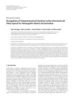
Figure 5 shows the baseband-SA modem for the m-WiMAX
SA BS. The SA modem consists of eight fixed point digital
signal processors (DSPs), two field programmable gate arrays
(FPGAs), and a general purpose processor (GPP). In the
modem, three DSPs exist for redundancy and are not used for
signal processing. Five DSPs are used for encoding/decoding,
beamforming, calibration, and ranging processing. Two
FPGAs perform FFT/IFFT and permutations. Finally, the
GPP is used for medium access control (MAC) to interface
between the SA BS and the network. The detailed function-
ality of each device is described as follows.
Figure 6 shows the signal flow of the baseband as well
as the allocation of the signal processing components to the
devices in the SA modem. In the case of UL, the received
signal is fed into the frontFPGA via low-voltage differential
signaling (LVDS). The frontFPGA removes the CP of the
received OFDMA symbols and passes it to the rearFPGA. The
rearFPGA performs FFT, tile permutation, and UL weight-
ing. The ranging code is also descrambled in the rearFPGA.
The descrambled ranging channel is passed to RNG
DSP
for estimating the symbol timing, and the data channel is
passed to UL
DSP for decoding. The beamforming-weight
vector is calculated by BF
DSP using the pilots embedded
in the permutated data channel. The BF
DSP returns the
weight vector to the rearFPGA. The weight vector is used
for both UL and DL, since the m-WiMAX is operated in
time-division duplex (TDD) mode. The decoded data is
analyzed in MAC
GPP and sent to the network. In DL,
the MAC protocol data unit (PDU) is fed into DL
DSP for
encoding. The encoded data is passed to the rearFPGA for DL
weighting, cluster permutation, and IFFT. The frontFPGA
receives the OFDMA symbol and adds the CP. When the DL
frame clock is enabled, the frontFPGA sends the OFDMA
symbol to the intermediate frequency (IF) module via
LVDS. The calibration is performed independently of UL/DL
processing. The result of the calibration is multiplied with the
weight vector in BF
DSP to compensate for the amplitude
and phase differences among the RF/IF chains.
Figure 7 describes how the signal processing is performed
in synchronization with the system clock. The system clock
(sysClk in Figure 7) generates a 10 MHz pulse. The frmSync
is raised at the beginning of every frame duration, and
UL
DL is toggled at every DL and UL duration. In Figure 7,
we can see that all signal processes in Figure 6 are performed
in parallel.
Figure 8 is a photograph of the up-down converter unit
(UDCU) employed in our SA BS. The UDCU consists
of an analog-to-digital (A/D) converter, a digital-to-analog
(D/A) converter, an Up/Down converter, and automatic gain
control (AGC). When transmitting, the digital data from the
SA modem is converted to the corresponding analog signal
through D/A conversion. This analog signal is converted
to an RF signal via the Up-converter. Then, the RF signal
is transmitted through the front-end unit (FEU). When
receiving, the received signal obtained from the FEU is first
fed into the AGC. Then, the output of the AGC is converted
to a digital signal which is sent to the SA modem.
The FEU, shown in Figure 9, includes a TDD switch and
a low-noise amplifier (LNA). The TDD switch isolates the
transmit and receive signals from each other in accordance
with the DL and UL duration. The LNA amplifies the
received signal with a noise level that is as low as possible.
The array antenna was implemented using five patch-
type elements. The element spacing was a half-wavelength
(6.52 cm). Four elements were used for transmitting and
receiving signals, and the other element was used for
calibration.
The signal processing modules presented in this section
were integrated into the m-WiMAX SA BS. A photograph
of the entire SA BS is provided with a description of the
experimental environment in the next section.
4. Experimental Results
In this section, experimental results obtained from the
implemented m-WiMAX SA BS are presented, including
the symbol-timing estimation probability for the ranging
process, the accuracy of the phase-delay compensation for
the calibration, and throughput. In addition, various com-
puter simulations supported the validity of our experimental
results.
Figure 10 shows the experimental environment that
included the implemented m-WiMAX SA BS, a six-element
array antenna, mobile-station emulator, signal generator,
spectrum analyzer, and server and client laptops which were
6 EURASIP Journal on Wireless Communications and Networking
Remove
CP
Remove
CP
FFT
FFT
Tile
permutation
Channel
estimation
IFFT
Add
CP
Buffer
frontFPGA
IFFT
Add
CP
Buffer
Buffer
Tile
permutation
Cluster
permutation
Cluster
permutation
Subcarrier
rearrange
Digital
demodulation
Slot
concatenation
Bit
deinterleaver
Zero
padding
Channel
decoding
Randomization
Ranging code
correlator
Slot
concatenation
Randomization
Channel
coding
Puncturing
Bit
interleaver
Digital
modulation
Subcarrier
arrange
Pilot
insertion
Ranging code
detector
RNG_DSP
Delay
estimation
ranging_code_num
propagation_delay
MAC_GPP
MAC
PDU
MAC
PDUUL_DSP
DL_DSP
CAL_DSP
Calibration
processing
Weight
calculation
BF_DSP
rearFPGA
DL
weighting
UL
weighting
LVDS RX/TX
Figure 6: Functional allocation for baseband modem of the SA system.
sysClk
frmSync
UL_DL
UL
DL
UL
DL
frontFPGA
Buffering OFDM symbol transmiting
Buffering
Buffering
OFDM symbol transmiting
Add CP
Add CP
OFDM symbol receiving
OFDM symbol receiving
Remove CP Remove CP
RX_Calibration signal transmiting
TX_Calibration signal transmiting
RX_Calibration signal transmiting TX_Calibration signal transmiting
Buffering Buffering
Receiving RX_Calibration signal
Receiving TX_Calibration signal Receiving RX_Calibration signal Receiving TX_Calibration
rear FPGA
IFFT
IFFT
Cluster permutation Cluster permutation
DL_weighting DL_weighting
FFT
FFT
Tile permutation
UL_weighting UL_weighting
Turbo decoding
ranging_code correlation
BF_DSP
Weight calculating
Weight calculating
CAL_DSP
RX_Cal calculation
TXCal signal generating
TX_Cal calculation
TXCal signal generating
TX_Cal calculation
RXCal signal generating
RX_Cal calculation
RNG_DSP
Ranging processingRanging processing
DL_DSP
UL_Symbol processing UL_Symbol processing
UL_Symbol processing
DL_Symbol processing DL_Symbol processing
UL_DSP
Tu rbo decoding
Tile permutation
Ranging_code correlation
Figure 7: Timing diagram for baseband signal processing.
connected to the BS and MS via Ethernet. Four elements
of the array antenna were used to transmit and receive the
m-WiMAX signal, and the other element was used for the
proposed calibration. An additional element, connected by
the spectrum analyzer, was used for measuring the signal-
to-noise ratio (SNR) at the RF input of the SA BS. The
signal generator radiated additive white Gaussian noise for
handling the SNR. To compare the performance between
the SA BS and the conventional single antenna BS, two SA
modems for the SA BS were used simultaneously. One SA
modem was set to the conventional single-antenna mode by
receiving the signal from an element of the array antenna,
and the other modem was set to the SA mode. The system
parameters used in this test are summarized in Tab le 1 .
Figure 11 shows a comparison of the symbol-timing
estimation probability of the conventional ranging process
and the proposed ranging process. The experimental results
were obtained by averaging the measurements during 10 000
frames, that is, a 50-second period. In addition, the exper-
imental results coincided well with the results of computer
EURASIP Journal on Wireless Communications and Networking 7
UD/AD
converter #0
UD/AD
converter #1
AGC
LVDS block
Figure 8: Photograph of the UDCU for the m-WiMAX SA BS.
Figure 9: Photograph of the FEU for the m-WiMAX SA BS.
Table 1: System parameters of the implemented m-WiMAX SA BS.
System parameter Value
Channel bandwidth 8.75 MHz
FFT size 1024 point
CP ratio 1/8
Subcarrier spacing 11.156 KHz
OFDMA symbol duration 100.840 μs
Number of symbols (DL/UL) 27/15
Frame length 5 ms
Modulation scheme QPSK
Number of antennas (BS/MS) 4/1
simulations which were calculated by compensating for the
SNR in Figure 2. As shown in Figure 11, the proposed rang-
ing process provided about a 5.7 dB enhancement in symbol-
timing estimation probability compared to the conventional
ranging process.
Figures 12 and 13 show the measurements of the relative
phase differences between each RF/IF chain and a reference
RF/IF chain before and after the proposed calibration.
As shown in Figure 12, the relative phase delay at each
RF/IF chain differed from the others but remained nearly
constant over time. From the measurements, we observed
that the phase delay of the RF/IF chain associated with each
MS emulator
m-WiMAX SA BS
Spectrum
analyzer
Server/client
laptop
Signal
generator
Antenna for
signal generator
Array antenna for BS
Antenna for
MS
Figure 10: Photograph of experimental environment.
0.8
0.82
0.84
0.86
0.88
0.9
0.92
0.94
0.96
0.98
1
Symbol-timing estimation probability
−22 −20 −18 −16 −14 −12 −10
SNR @ RF input (dB)
L
= 4, computer simulation
L
= 4, experimental result
L
= 1, computer simulation
L
= 1, experimental result
Figure 11: Experimental results of the proposed ranging algorithm.
antenna element remained steady for a duration of over 500
symbols. Figure 13 shows the phase delay after the proposed
calibration. The standard deviation of the residual phase
error of the relative phase delay at each antenna element was
2-3
◦
andremainedsteadyforfivehours.Figure 13 shows
that the proposed calibration technique eliminated the phase
difference of the RF/IF chain associated with the antenna
elements.
Finally, Figure 14 shows the measured uplink throughput
of the conventional single-antenna BS and SA BS. The
experimental results were averaged over five minutes per
given SNR. To measure the throughput of both BSs, a
movie file was uploaded from the client laptop, which was
connected to the MS, to the server laptop connected to
the BS. In other words, the experiment was performed
with packet-based communication. As shown in Figure 14,
8 EURASIP Journal on Wireless Communications and Networking
−180
−120
−60
0
60
120
180
Phase characteristic (deg)
0 50 100 150 200 250 300 350 400 450 500
Time (OFDMA symbol duration)
Antenna 1
Antenna 0
Antenna 3
Antenna 2
Figure 12: Phase characteristics obtained by experiment before
calibration.
−180
−120
−60
0
60
120
180
Phase characteristic (deg)
0 50 100 150 200 250 300 350 400 450 500
Time (OFDMA symbol duration)
Antenna 0–3
Figure 13: Phase characteristics obtained by experiment after
calibration.
the proposed beamforming scheme provides a 5.5 dB link-
budget enhancement. These results mean that the proposed
beamforming scheme can be implemented. In addition, the
experimental results are consistent with the results from the
computer simulation.
5. Conclusion
In this paper, we addressed three key issues in implementing
the m-WiMAX SA BS: ranging, beamforming, and calibra-
tion.
First, the proposed ranging process significantly reduced
calculation loads using IFFT instead of a correlation opera-
tion. Moreover, the proposed process achieved diversity gain
in the received signals from each antenna path.
Second, the proposed beamforming scheme addressed
the lack of samples in OFDM-based packet communications.
The proposed scheme used time and frequency samples for
obtaining the statistical properties of the spatial channel.
Finally, the calibration method, which can be applied
while the SA system is operating, was proposed. Although
additional antenna chains are required, the proposed method
provided fast and accurate performance.
The experimental results and computer simulations
verified the validity of these solutions. As shown in Section 4,
the proposed solutions can be applied to the m-WiMAX SA
0
10
20
30
40
50
60
70
Throughput (Kbps)
−26 −24 −22 −20 −18 −16 −14 −12 −10 −8
SNR @ RF input (dB)
L
= 1, experimental result
L
= 4, experimental result
L
= 1, computer simulation
L
= 4, computer simulation
Figure 14: Throughput of implemented SA system obtained by
experiment.
BS. In addition, the m-WiMAX SA BS increased the link-
budget by 5.5 dB.
It should be noted that the experiments described in this
paper represent lab tests only, which might be quite different
from the outdoor environments in which m-WiMAX is used.
As shown in Figure 10, the MS in our lab tests was located
just 4-5 meters away from the BS in a direct line of sight.
Since a mobile fading environment cannot easily be set up
in the laboratory, we checked the proposed beamforming
scheme in fading environments through various computer
simulations. As shown in Figures 2 and 4, it is clear that
the proposed beamforming scheme provided a remarkable
improvement in mobile fading environments as well as in the
static circumstances of the lab tests. Another limitation of the
experimental tests was that the calibration performance was
not verified in the throughput tests shown in Figure 14.Note
that as the calibration was used for downlink beamforming,
the uplink performance shown in this paper does not
confirm the validity of the proposed calibration procedure
except that the phase differences at each antenna channel
were equalized as shown in Figures 12 and 13. Future tests
could include the downlink measurements to verify the
actual performance of the proposed calibration procedure.
Acknowledgments
This work was partly supported by the IT R&D program
of MIC/IITA (2007-S001-01, Implementation of Advanced-
MIMO system) and the HY-SDR research center at Hanyang
University, Seoul, South Korea under the ITRC program of
MIC, South Korea.
EURASIP Journal on Wireless Communications and Networking 9
References
[1] WiMAX Forum, “Mobile WiMAX—part I: a technical over-
view and performance evaluation,” axforum
.org/.
[2] Y. Li and N. R. Sollenberger, “Adaptive antenna arrays for
OFDM systems with cochannel interference,” IEEE Transac-
tions on Communications, vol. 47, no. 2, pp. 217–229, 1999.
[3] Y F. Chen and C P. Li, “Adaptive beamforming schemes for
interference cancellation in OFDM communication systems,”
in Proceedings of the 59th IEEE Vehicular Technology Conference
(VTC ’04), vol. 1, pp. 103–107, Milan, Italy, May 2004.
[4] M. Wennstr
¨
om, T.
¨
Oberg, and A. Rydberg, “Effects of finite
weight resolution and calibration errors on the performance of
adaptive array antennas,” IEEE Transactions on Aerospace and
Electronic Systems, vol. 37, no. 2, pp. 549–562, 2001.
[5] J. J. van de Beek, M. Sandell, and P. O. B
¨
orjesson, “ML
estimation of timing and frequency offset in OFDM systems,”
IEEE Transactions on Signal Processing, vol. 45, no. 7, pp. 1800–
1805, 1997.
[6] X. Fu and H. Minn, “Initial uplink synchronization and power
control (ranging process) for OFDMA systems,” in Proceedings
of the IEEE Global Telecommunications Conference (GLOBE-
COM ’04), vol. 6, pp. 3999–4003, IEEE Communications
Society, Dallas, Tex, USA, November-December 2004.
[7] S. Choi and D. Shim, “A novel adaptive beamforming
algorithm for a smart antenna system in a cdma mobile
communication environment,” IEEE Transactions on Vehicular
Technology, vol. 49, no. 5, pp. 1793–1806, 2000.
[8]J.LitvaandT.K.Lo,Digital Beamforming in Wireless
Communications, Artech House, Norwood, Mass, USA, 1996.
[9] S. Mano and T. Katagi, “A method for measuring amplitude
and phase of each radiating element of a phased array
antenna,” Journal of the Institute of Electronics and Communi-
cation Engineers of Japan, vol. 65, no. 5, pp. 555–560, 1982.
[10] K. Nishimori, K. Cho, Y. Takatori, and T. Hori, “Automatic
calibration method of adaptive array for FDD systems,” in
Proceedings of the IEEE Antennas and Propagation Society
International Symposium (APS ’00), vol. 2, pp. 910–913, Salt
Lake, Utah, USA, July 2000.
[11] S. Hyeon, Y. Yun, and S. Choi, “Novel automatic calibration
technique for smart antenna systems,” DigitalSignalProcess-
ing, vol. 19, no. 1, pp. 14–21, 2009.