Báo cáo hóa học: " Research Article Centroid Localization of Uncooperative Nodes in Wireless Networks Using a Relative Span Weighting Method" pot
Bạn đang xem bản rút gọn của tài liệu. Xem và tải ngay bản đầy đủ của tài liệu tại đây (911.39 KB, 10 trang )
Hindawi Publishing Corporation
EURASIP Journal on Wireless Communications and Networking
Volume 2010, Article ID 567040, 10 pages
doi:10.1155/2010/567040
Research Article
Centroid Localization of Uncooperative Nodes in
Wireless Networks Using a Relative Span Weighting Method
Christ ine Laurendeau and Michel Barbeau
School of Computer Science, Carleton University, 1125 Colonel By Drive, Ottawa, ON, Canada K1S 5B6
Correspondence should be addressed to Christine Laurendeau,
Received 19 August 2009; Accepted 21 September 2009
Academic Editor: Benyuan Liu
Copyright © 2010 C. Laurendeau and M. Barbeau. This is an open access article distributed under the Creative Commons
Attribution License, which permits unrestricted use, distribution, and reproduction in any medium, provided the original work is
properly cited.
Increasingly ubiquitous wireless technologies require novel localization techniques to pinpoint the position of an uncooperative
node, whether the target is a malicious device engaging in a security exploit or a low-battery handset in the middle of a critical
emergency. Such scenarios necessitate that a radio signal source be localized by other network nodes efficiently, using minimal
information. We propose two new algorithms for estimating the position of an uncooperative transmitter, based on the received
signal strength (RSS) of a single target message at a set of receivers whose coordinates are known. As an extension to the concept
of centroid localization, our mechanisms weigh each receiver’s coordinates based on the message’s relative RSS at that receiver,
with respect to the span of RSS values over all receivers. The weights may decrease from the highest RSS receiver either linearly or
exponentially. Our simulation results demonstrate that for all but the most sparsely populated wireless networks, our exponentially
weighted mechanism localizes a target node within the regulations stipulated for emergency services location accuracy.
1. Introduction
Given the pervasiveness of cellphones and other wireless
devices, compounded with the associated expectation of
permanent connectivity, it is perhaps not surprising that the
abrupt dashing of such presumptions makes headline news.
A recent spate of cases in Canada has highlighted the tragic
consequences of failing to locate the source of an emergency
911 cellphone call. In one incident, a New Year’s Eve reveler
lost in a snowstorm in the middle of the British Columbia
woods called 911 for help, but the police were only able to
find the teen over 12 hours later, after he had perished [1]. In
September 2008, the body of a badly beaten man in Alberta
was located four days after his ill-fated call for help [2]. A
more recent case had two children lost in snowy conditions
who were lucky to survive when discovered several hours
after their initial 911 call [3]. These and similar events have
spurred the Canadian Radio-television Telecommunications
Commission (CRTC) to regulate the same wireless Enhanced
911 (E911) provisions [4] as the Federal Communications
Commission (FCC) in the U.S. [5]. Under Phase II of the
FCC and CRTC plans, localization efforts based on a handset
device (handset-based) must yield a location accuracy of 50
meters in 67% of cases and 150 meters 95% of the time.
Network-based localization, where other nodes (whether
base stations or other handsets within range) estimate the
position of a device, must accurately reveal a target location
within 100 meters 67% of the time and within 300 meters in
95% of cases.
Self-localization achieved with handset-based techniques
can produce granular results. For example with the Global
Positioning System (GPS), a precision of ten meters may
be achieved [6]. But self-localization is not feasible in all
scenarios. An uncooperative node is one that cannot be relied
upon to determine its coordinates, for example, a defective
sensor, a malicious device engaging in a security exploit,
or a low-battery handset in a critical situation. A malicious
node broadcasting an attack message cannot be expected
to cooperate with efforts to uncover its position. In other
situations, a malfunctioning device or one whose battery
is nearly drained may be unable to compute and report
its coordinates to other nodes. Network-based localization
schemes are thus essential in order to fill the gap. A large
body of location estimation literature already exists, much
2 EURASIP Journal on Wireless Communications and Networking
of it centered on self-localization. With GPS technology
becoming more affordable, highly performing and well adept
at filling the handset-based requirements, we focus our
efforts on network-based localization and the inherently
more complex scenarios it addresses.
In a sufficiently densely populated wireless network, the
source location of a given message may be approximated
from the coordinates of receiving devices, assuming an omni-
directional propagation pattern. We propose two localization
algorithms that estimate a transmitting node’s position as
the weighted average of receiver coordinates, assuming that a
single message is received from the target node. We compute
a received signal strength (RSS) span as the difference
between the maximum and minimum RSS values for the
transmitted message over all receivers. We assign greater
weight to the receiver coordinates whose RSS value is closer
to the maximum of the RSS span and thus closer to the
transmitter. Conversely, lesser weight is ascribed to receivers
with lower RSS values, as they are deemed farther from the
transmitter. We describe a relative span we ighted localization
(RWL) mechanism, where the concept of weighted moving
average is adapted to provide a linear mapping between the
weight assigned to a receiver’s coordinates and the relative
placement of its RSS value within the overall RSS span. We
further propose an exponential variation of RWL, dubbed
relative span exponential w eighted localization (REWL). This
approach is conceptually related to an exponential moving
average and relies on an exponential weight correspondence
between a receiver’s coordinates and its relative situation
within the RSS span. We evaluate the RWL and REWL
algorithms using simulated RSS reports featuring a variety
of node densities, number of receivers, and amount of
signal shadowing representative of environment-based RSS
fluctuations. We also test our localization mechanisms with
RSS values harvested from an outdoor field experiment.
We find that the exponentially weighted variation achieves
better results and that, except for cases with a small number
of receivers and a large amount of signal shadowing, our
mechanism meets the E911 mandated location accuracy
requirements.
Section 2 provides an overview of existing work in
wireless node localization. Section 3 outlines the centroid
localization schemes on which our new algorithms are based.
Section 4 describes our linearly and exponentially weighted
location estimation mechanisms. Section 5 evaluates the
performance of both algorithms using simulated and experi-
mental RSS values. Section 6 concludes the paper.
2. Related Work
The problem of wireless node localization may be
approached from one of two main directions: device
based (also known as handset-based) and network based.
Device-based self-localization involves a node seeking to
learn its own position, occasionally with the help of other
trusted devices within radio range. For example, the use of
GPS can be seen as a device-based approach, since a node
uses information supplied by a set of satellites in order
to determine its coordinates. In techniques based on time
of arrival (TOA), a device may situate its position with
respect the known locations of other nodes by correlating
arrival time of received messages and thus determining its
distance to each node. A large proportion of the localization
techniques proposed for sensor networks assume a device-
based approach. For example, the three/two neighbor
algorithm proposed by Barbeau et al. [7]allowsfora
sensor of unknown position to estimate its location from
the coordinates of neighboring nodes, based on their
respective TOA-approximated distances. While device-based
mechanisms can achieve high localization accuracy, they are
unsuitable for positioning attackers or uncooperative nodes.
Given that such devices may supply erroneous location
information, either willfully or accidentally, they must be
located by other network nodes using measurements that
cannot easily be forged.
The concept of triangulation was first introduced by Fri-
sius [8] for map surveying and locating far-off geographical
points. In more recent years, this approach has also served
as a network-based technique to localize a transmitting
device using two receivers of known coordinates and the
transmission’s angle of arrival. A significant drawback of
the triangulation method is the necessity that receivers
be equipped with directional antennas, so that the angle
at which an incoming transmission originates may be
measured. Without this specialized hardware, triangulation
is not feasible.
We focus our research efforts on network-based location
estimation mechanisms that assume the more commonly
available omnidirectional antennas. In existing work, such
schemes typically yield results in either open-form, where a
target node is localized to an estimated area in Euclidean
space, or in closed-form, where the coordinates of a single
point are determined.
Open-form solutions may be constructed as the intersec-
tion of rings, or annuli, around the receivers of a particular
message, as suggested by Barbeau and Robert [9], as well
as Liu et al. [10]. In such mechanisms, the minimum and
maximum distances between a transmitter and each receiver
are approximated from a signal path loss propagation model,
such as the log-normal shadowing model [11]. However, the
effective isotropic radiated power (EIRP) must be known,
which may not be feasible in an attack message scenario. In
hyperbolic position bounding, first described by Laurendeau
and Barbeau [12], the EIRP is assumed to be unknown, and
hyperbolic areas are computed from an estimated distance
difference range between a transmitter and each pair of
receivers. The intersection of constructed hyperbolic areas
suggests a candidate area for the location of a transmitter.
While open-form solutions may localize a node within an
area with a suitable degree of granularity for certain types
of applications, other scenarios may require a more precise
localization result.
Closed-form solutions abound in the literature as well.
The time difference of arrival (TDOA) approach translates
the difference in arrival times of a given message at two
receivers into a distance difference and plots a hyperbola with
the receiver coordinates as foci. Multiple receiver pairs yield
EURASIP Journal on Wireless Communications and Networking 3
multiple hyperbolas, with a transmitter location determined
at the common intersecting point. With this technique,
the clocks at receiving devices must be synchronized with
nanosecond precision; otherwise a common intersecting
point may not exist. Even highly correlated GPS clocks
may exhibit up to one microsecond of clock drift between
receivers [13]. At the speed of light, a one microsecond drift
translates into a distance difference of 300 meters, resulting in
a margin of location error greater than the FCC regulations
for E911 location accuracy. The RSS values of a given message
may be used to estimate a set of transmitter-receiver (T-
R) distances using a least squares approach, as suggested
by Zhong et al. [14] and Liu et al. [15, 16]. Disadvantages
of these schemes include their reliance upon a nearly-ideal
radio propagation environment, with little signal noise, as
well as the availability of multiple transmitted messages so
that the signal fluctuations can be averaged out. Even in a
moderately shadowed environment, such approaches may
fail to yield any solution.
In the realm of sensor networks, centroid localization
(CL) has been suggested as an efficient closed-form method
that never fails to produce a solution. The original incarna-
tion of CL is described by Bulusu et al. [17] and localizes the
transmitting source of a message to the (x, y) coordinates
obtained from averaging the coordinates of all receiving
devices within range. Weighted centroid localization (WCL),
as proposed by Blumenthal et al. [18], assigns a weight to
each of the receiver coordinates, as inversely proportional to
either the known T-R distance or the link quality indicator
available in ZigBee/IEEE 802.15.4 sensor networks [19].
Behnke and Timmermann [20] extend the WCL mechanism
for use with normalized values of the link quality indicator.
Schuhmann et al. [21] conduct an indoor experiment to
determine a set of fixed parameters for an exponential inverse
relation between T-R distances and the corresponding
weights used with WCL. Orooji and Abolhassani [22]suggest
a T-R distance-weighted averaged coordinates scheme, where
each receiver’s coordinates is inversely weighted according to
its distance from the transmitter. But this approach assumes
that the receivers are closely colocated and that the T-R
distance to at least one of the receivers is known a priori.
3. Centroid Localization
We outline the centroid localization approaches on which
our novel algorithms are based and introduce the notation
used throughout the description of our mechanisms.
Notation. The estimated coordinates of the transmitter we
are striving to locate are denoted as
p = (x, y). Each receiver
R
i
is situated at a point of known coordinates p
i
= (x
i
, y
i
).
For the sake of simplicity in our algorithm descriptions,
we depict operations on receiver points p
i
. In fact, two
separate calculations occur. The approximated
x coordinate
is computed from all the receiver x
i
coordinates, and y is
calculated from the y
i
coordinates.
Given a set of known points p
i
in a Euclidian space, for
example, a number of receivers within radio range of a target
transmitter to be localized, Bulusu et al. [17] approximate the
location
p of a node from the centroid of the known points
p
i
as follows:
p =
1
n
×
n
i=1
p
i
,
(1)
where n represents the number of points.
In the simple CL approach, all points are assumed to be
equally near the target node. Blumenthal et al. [18] argue
that some points are more likely than others to be close to
target node. Their WCL scheme aims to improve localization
accuracy by assigning greater weight to those points which
are estimated to be closer to the target and less weight to the
farther points. The weighted centroid is thus computed as
p =
n
i=1
w
i
× p
i
n
i
=1
w
i
(2)
with
w
i
=
1
(
d
i
)
g
,(3)
where d
i
is the known distance between the target node and
point p
i
, and the exponent g influences the degree to which
remote points participate in estimating the target location
p.
Valu es o f g are determined manually, with Blumenthal et al.
[18] and Schuhmann et al. [21] promoting different optimal
values, depending on the experimental setting.
4. Relative Span Weighted Localization
Assuming an uncooperative node, we cannot presume to
know apriorithe set of T-R distances d
i
or the optimal
value of g in a given outdoor environment. Further, we
cannot estimate values of d
i
from the log-normal shadowing
model, as the transmitter EIRP may not be known. We
therefore introduce the concept of relative span weighted
localization in order to estimate the location of a transmitter
with minimal information available at a set of receivers.
Our approach adapts the concept of moving average from
a weighting method over time and applies it to WCL in the
space domain. But rather than ascribing weights according
to known or approximated T-R distances, we weigh each
receiver coordinates according to the relative placement of
its RSS value within the span of all RSS reports for a
given transmitted message. The receiver coordinates may be
weighted linearly or exponentially.
Definition 4.1 (minimal/maximal RSS). Let
R be the set of
all receivers within range of a given message M
T
originating
from an uncooperative transmitter T.LetΥ denote the set
ofRSSvaluesmeasuredateachreceiverR
i
∈ R for message
M
T
, such that
Υ
=
υ
i
: υ
i
is the RSS value for message M
T
at R
i
∀R
i
∈ R}.
(4)
4 EURASIP Journal on Wireless Communications and Networking
Then we define the minimal and maximal RSS values, V
min
and V
max
, for message M
T
, as the smallest and largest RSS
values in Υ:
V
min
= min{υ
i
∈ Υ},
V
max
= max{υ
i
∈ Υ}.
(5)
Definition 4.2 (RSS span). Let the minimal and maximal RSS
values for a message M
T
be as stated in Definition 4.1.We
define the RSS span V
Δ
for this message at a set of receivers
R as the maximal range in RSS values over all receivers:
V
Δ
= V
max
−V
min
. (6)
We describe two relative span weighted localization algo-
rithms, both computing a weighted centroid as defined in
(2), but with novel approaches for computing the weights
assigned to each receiver coordinates.
4.1. Linearly Weighted Localization. The RWL algorithm
computes a centroid of receiver coordinates, each weighted
linearly according to the relative position of the receiver’s RSS
value within the RSS span.
Algorithm 4.3 (RWL algorithm). The relative span weighted
localization (RWL) algorithm estimates a transmitter’s coor-
dinates
p as the weighted centroid of all receiver coordinates
p
i
,asdefinedforWCLin(2), but with a linearly increasing
weight assigned to each receiver according to its presumed
proximity to the transmitter. Given the RSS values in Υ,as
found in Definition 4.1, and the RSS span V
Δ
determined
according to Definition 4.2, the weight w
i
of each receiver R
i
is computed from the relative placement of its RSS value υ
i
in the RSS span, as follows:
w
i
=
υ
i
−V
min
V
Δ
for each R
i
∈ R. (7)
The relative span weighted centroid thus becomes
p =
n
i
=1
(
υ
i
−V
min
)
× p
i
n
i
=1
(
υ
i
−V
min
)
,(8)
where n
=|R|.
4.2. Exponent ially Weig hted Localization. Exponentially
weighted moving averages (EMAs) have been used for a
variety of forecasting applications, for example, in Muir
[23], to predict future values based on past observations,
with more weight exponentially ascribed to more recent
data. A weighting factor λ is used as a parameter to control
the proportion of weight assigned to recent observations
with respect to past ones.
According to [24], the EMA at time t is stated as
EMA
t
= λ ×Z
t
+
(
1 −λ
)
×EMA
t−1
,(9)
where λ is the weighting factor, Z
t
is an observation at time t
and EMA
0
is the average of historical observation values.
Roberts [25] expands the EMA equation as follows:
EMA
t
= λ ×
n
i=1
(
1
−λ
)
t−i
×Z
i
, (10)
where n is the number of observations.
We adapt the EMA concept from rating observations
over time for the purpose of weighting receiver coordinates
over the space domain. While EMA favors more recent
observations in time with a weighting factor of λ, we bolster
receivers that are likely to be closer to a transmitter and thus
feature higher RSS values. In addition, rather than increasing
the weighting factor exponent by one for each observation in
time, we correlate the exponent with the relative position of
each receiver’s RSS value within the RSS span.
Algorithm 4.4 (REWL algorithm). The relative span expo-
nentially weighted localization (REWL) algorithm estimates
a transmitter’s coordinates
p as the weighted centroid of all
receiver coordinates p
i
,asdefinedforWCLin(2), but with
exponential weight assigned to each receiver according to a
weighting factor λ. Given the RSS values in Υ as found in
Definition 4.1, the weight w
i
of each receiver R
i
is computed
from the relative placement of its RSS value υ
i
in the RSS span
as follows:
w
i
=
(
1
−λ
)
(V
max
−υ
i
)
for each R
i
∈ R. (11)
The relative span exponentially weighted centroid thus
becomes
p =
n
i
=1
(
1
−λ
)
(V
max
−υ
i
)
× p
i
n
i
=1
(
1
−λ
)
(V
max
−υ
i
)
,
(12)
where n
=|R|.
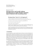
4.3. Example. Figure 1 compares the relative weights
assigned to a set of receivers with an RSS span V
Δ
of 15 dBm,
given the RWL and REWL weight assignments, assuming
three different values for the weighting factor λ. The REWL
algorithm with λ
= 0.10, equivalent to a smoothing factor
of 10%, represents the flattest of the exponential curves
and thus the closest to the constant weighting approach of
simple CL. Less weight is assigned to receivers closest to
the transmitter and more weight to those farthest, when
compared to the linear RWL method. With λ
= 0.20, the
nearest receivers are ascribed far greater weight than under
the RWL scheme, and the mid-RSS receivers are given much
less importance. A weight factor of λ
= 0.15 strikes a balance
between the two, with the highest RSS receivers assigned
slightly more weight than with RWL, the mid-RSS receivers
somewhat less, while the lowest still contribute marginally to
estimating the transmitter location.
5. Performance Evaluation
We evaluate the performance of the RWL and REWL
algorithms using simulated RSS values and experimental
ones harvested from an outdoor field experiment.
EURASIP Journal on Wireless Communications and Networking 5
0
0.05
0.1
0.15
0.2
0.25
Receiver weight
−90 −85 −80 −75
Receiver RSS (dBm)
RWL
REWL, λ
= 0.1
REWL, λ
= 0.15
REWL, λ
= 0.2
Figure 1: Example of relative span weights.
5.1. Simulation Results. We ran the RWL and REWL mech-
anisms on simulations featuring a variety of node densities
and number of receivers. For each of 10 000 executions, we
generate a random transmitter position within a 1000
×
1000 m
2
simulation grid. We define our node densities as
the number of nodes per 100
× 100 m
2
.Foreverynode
density d
∈{0.25, 0.50, 0.75, 1, 2, 3, 4, 5, 6,7,8,9,10},we
position d nodes per 100
× 100 m
2
in uniformly distributed
positions on our simulation grid. For each node, we compute
a RSS value based on the log-normal shadowing model
[11], with a random amount of signal shadowing generated
along a Gaussian probability distribution. We assume two
different radio propagation environments with path loss
constants obtained from outdoor experiments. For the
2.4 GHz WiFi/802.11g frequency, we use propagation values
measured by Liechty [26] and Liechty et al. [27], where a
signal shadowing standard deviation is measured at nearly
σ
= 6 dBm. For the 5.8 GHz frequency, licensed for vehicular
networks [28], we make use of the constants determined
by Durgin et al. [29], with a signal shadowing standard
deviation close to σ
= 8 dBm. Similar experiments by
Schwengler and Gilbert corroborate the amount of signal
shadowing commonly experienced at this frequency [30].
Our setup allows us to gauge the performance of relative span
weighted localization based on propagation environments
featuring different amounts of signal fluctuations. Once our
simulated nodes are positioned, we determine which ones
canbeusedasreceivers.Wesetallreceiversensitivityto
−90 dBm, and the nodes that feature a RSS value above
the sensitivity are deemed within range of the transmitter
and thus become receivers. The nonreceiver nodes are
subsequently ignored as out of range.
Ta ble 1 shows the average number of receivers for each
node density, over all our simulated executions, given each
radio propagation environment.
0
200
400
600
800
1000
0 100 200 300 400 500 600 700 800 900 1000
Node
Tr ans m itt er
Receiver
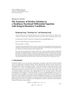
Figure 2: Example of simulation grid, density = 1 node per 100 ×
100 m
2
.
Table 1:Averagenumberofreceiverspernodedensity.
Node density (nodes per
100
×100 m
2
)
Frequency and shadowing
f
= 2.4GHz f = 5.8GHz
σ
= 6dBm σ = 8dBm
0.25
24
0.50
37
0.75
411
1
515
2
11 30
3
17 45
4
23 60
5
29 75
6
35 91
7
40 106
8
46 121
9
52 136
10
58 151
Figure 2 depicts an example simulation grid, with a
transmitter at 2.4 GHz, a number of nodes generated with
density of one node per 100
× 100 m
2
, and receivers within
range of the transmitter. It should be noted that some nodes
may be located closer to the transmitter and yet be out
of range. This is due to the different amounts of signal
shadowing generated for each node. So while one node may
be physically closer to the transmitter, if it experiences a large
amount of negative shadowing, its RSS value may fall below
the receiver sensitivity and thus be deemed undetectable.
For each execution, we use the known coordinates of all
receivers to compute a possible position for the transmitter,
according to four algorithms: the maximum RSS receiver
method, where a transmitter is assumed to be at exactly
the receiver position with the highest RSS value; the CL
approach, as set out by Bulusu et al. in (1); the RWL
algorithm using (8); the REWL algorithm as set forth in
(12), given three different values for the weighting factor
6 EURASIP Journal on Wireless Communications and Networking
0
20
40
60
80
100
Location error (meters)
0.5
1
3
5
7
10
Node density (nodes/100 m
2
)
Max RSS
CL
RWL
REWL, λ
= 0.2
REWL, λ
= 0.1
REWL, λ
= 0.15
Figure 3: Algorithm location error by node density for 2.4 GHz.
λ ∈{0.10, 0.15, 0.20}. We assess the performance of each
mechanism according to its location accuracy, computed as
the Euclidian distance between the estimated position
p and
the actual transmitter location, averaged over all executions.
Our results are deemed accurate within
±3 meters in a 95%
confidence interval.
Figures 3 and 4 plot the average location error for
each tested algorithm, given all defined node densities, for
frequencies 2.4 GHz and 5.8 GHz, respectively. We find that
while higher densities consistently yield greater location
accuracy, a larger amount of signal shadowing results in
higher location errors. For example, for all densities, the
REWL algorithm, with the 2.4 GHz frequency and σ
=
6 dBm, yields a location error consistently less than 75
meters, while the same mechanism at the 5.8 GHz frequency
and σ
= 8 dBm reaches an error of 105 meters. For both
frequencies and all node densities, the REWL algorithm with
weighting factor of 15% (λ
= 0.15) achieves optimal results.
Thesameobservationscanbemadewhennodesare
generated by absolute numbers of receivers rather than
node densities. Figures 5 and 6 demonstrate the location
errors computed with each algorithm with fixed numbers
of receivers, given the 2.4 GHz and 5.8 GHz frequencies,
respectively. Again, with similar numbers of receivers, the
least shadowed environment produces lower location errors.
As with the tests involving different node densities, the
REWL mechanism with λ
= 0.15 performs better than the
other algorithms for all numbers of receivers.
In order to gauge the performance of REWL (λ
= 0.15)
for a single frequency and different levels of environmental
shadowing, we executed the algorithm at 2.4 GHz with three
separate amounts of shadowing generated on the simulated
RSS values: σ
∈{6, 8, 10}dBm. As Figure 7 reveals, higher
levels of shadowing have a significant impact on location
error, with an error increase of roughly 50% for every 2 dBm
0
50
100
150
Location error (meters)
0.5
1
3
5
7
10
Node density (nodes/100 m
2
)
Max RSS
CL
RWL
REWL, λ
= 0.2
REWL, λ
= 0.1
REWL, λ
= 0.15
Figure 4: Algorithm location error by node density for 5.8 GHz.
0
20
40
60
80
100
120
Location error (meters)
2
4
8
16
Number of receivers
Max RSS
CL
RWL
REWL, λ
= 0.1
REWL, λ
= 0.2
REWL, λ
= 0.15
Figure 5: Algorithm location error by number of receivers for
2.4 GHz.
of additional signal shadowing standard deviation, for each
node density.
We assessed the performance of each algorithm, and in
particular the REWL (λ
= 0.15) mechanism, when compared
to the E911 regulations for location accuracy. Figures 8 and 9
show the location error cumulative probability distribution
for each algorithm, given four receivers, for the 2.4 GHz
and 5.8 GHz frequencies, respectively. While every method
evaluated meets the E911 requirements at 2.4 GHz with
moderate signal shadowing (σ
= 6 dBm), none of the
mechanisms succeed with 5.8 GHz and a larger amount of
EURASIP Journal on Wireless Communications and Networking 7
0
50
100
150
200
Location error (meters)
2
4
8
16
Number of receivers
Max RSS
CL
RWL
REWL, λ
= 0.2
REWL, λ
= 0.1
REWL, λ
= 0.15
Figure 6: Algorithm location error by number of receivers for
5.8 GHz.
0
20
40
60
80
100
120
140
Location error (meters)
0.25
0.75
2
4
6
8
10
Node density (nodes/ 100 m
2
)
6
8
10
σ
= 10
σ
= 8
σ
= 6
Figure 7: REWL (λ = 0.15) location error by signal shadowing for
2.4 GHz.
shadowing (σ = 8 dBm). However, even in the latter case,
the REWL approach with λ
= 0.15 is nearly adequate.
The REWL algorithm, with λ
= 0.15, was evaluated for
different node densities, with the two different frequencies.
Given the smaller amount of signal shadowing found at
2.4 GHz, REWL meets the E911 location accuracy require-
ments for every node density, as seen in Figure 10.Forlarger
amounts of shadowing at 5.8 GHz, only the smallest node
density of 0.25 per 100
× 100 m
2
fails to meet the E911
standard, as shown in Figure 11. Even in a heavily shadowed
environment, higher node densities can accurately localize a
0
0.1
0.2
0.3
0.4
0.5
0.6
0.7
0.8
0.9
1
Cumulative probability
0 100 200 300 400 500 600
Location error (meters)
Max RSS
CL
RWL
REWL, λ
= 0.15
E911
Figure 8: Algorithm location error CDF for four receivers at
2.4 GHz.
0
0.1
0.2
0.3
0.4
0.5
0.6
0.7
0.8
0.9
1
Cumulative probability
0 100 200 300 400 500 600
Location error (meters)
Max RSS
CL
RWL
REWL, λ
= 0.15
E911
Figure 9: Algorithm location error CDF for four receivers at
5.8 GHz.
transmitter within 100 meters 67% of the time and within
300 meters in 95% of cases.
Orooji et al. [22] simulate a cluster of seven cells, each
featuring a base station with a one kilometer radius, in order
to compute the location of a mobile station. A very small
amount of signal shadowing σ
∈{1, 2}dBm is taken into
account. Even though their proposed T-R distance-weighted
method assumes a known distance to one of the base stations,
the mean location error is 48 meters, with 95% of executions
resulting in a location error less than 103 meters. Our RWL
8 EURASIP Journal on Wireless Communications and Networking
0
0.1
0.2
0.3
0.4
0.5
0.6
0.7
0.8
0.9
1
Cumulative probability
0
100 200 300 400 500 600
Location error (meters)
Density
= 0.25
Density
= 0.5
Density
= 0.75
Density
= 1
Density
= 2
E911
Figure 10: REWL location error CDF by node density for 2.4 GHz.
0
0.1
0.2
0.3
0.4
0.5
0.6
0.7
0.8
0.9
1
Cumulative probability
0 100 200 300 400 500 600
Location error (meters)
Density
= 0.25
Density
= 0.5
Density
= 0.75
Density
= 1
Density
= 2
E911
Figure 11: REWL location error CDF by node density for 5.8 GHz.
and REWL (λ = 0.15) algorithms for 2.4 GHz with eight
receivers yield an average 37 and 34 meter location error,
respectively. RWL locates a transmitter within 100 meters
98% of the time, while REWL does so in 99% of cases. Thus
over a similarly sized simulation grid, our RWL and REWL
mechanisms consistently yield more accurate results.
5.2. Experimental Results. We con duc ted an o utdo or fie ld
experiment with four desktop receivers statically arranged
in the corners of a rectangular area 80
× 110 m
2
in size.
Each receiver collected the RSS values of packets transmitted
0
10
20
30
40
50
60
70
Location error (meters)
1
2
3
4
5
6
7
8
9
10
Transmitter location
Max RSS
CL
RWL
REWL, λ
= 0.1
REWL, λ
= 0.2
REWL, λ
= 0.15
Figure 12: Algorithm location error for experimental data.
Table 2: Average location error for all transmitter locations.
Algorithm
Average location error
(meters)
Max RSS 40
CL 46
RWL 28
REWL (λ
= 0.10) 33
REWL (λ
= 0.15) 29
REWL (λ
= 0.20) 28
by a laptop from each of ten separate locations. Only the
messages simultaneously received by the four desktops were
retained. The localization algorithms were executed on each
message, and the average location errors for each transmitter
location are depicted in Figure 12. The location error for
each algorithm averaged over all transmitter locations can
be found in Ta ble 2 . We find that the RWL and REWL
mechanisms perform far better than the maximum RSS
receiver and CL approaches, with a gain in location accuracy
of up to 40%. On average, the RWL, REWL with λ
= 0.15,
and REWL with λ
= 0.20 mechanisms perform equally well,
with no algorithm emerging as clearly superior to the others.
This may be due to our small experimental data set (approx-
imately 400 messages), when compared to simulation results
obtained over 10 000 executions. While our simulations also
found consistently similar results between the RWL and
REWL mechanisms, the larger amount of simulated data
allows us to draw more fine-tuned conclusions.
6. Concl usion
We propose a wireless network-based localization mech-
anism for estimating the position of an uncooperative
transmitting device, whether it is a malfunctioning sensor,
EURASIP Journal on Wireless Communications and Networking 9
an attacker engaging in a security exploit, or a low-battery
cellphone in a critical emergency. We extend the concept of
weighted centroid localization and describe two additional
receiver coordinate weighting mechanisms, one linear and
the other exponential, that assume no knowledge of the T-R
distances nor of the transmitter EIRP. We adapt the concept
of moving averages based on observations over time to the
space domain. We ascribe linear and exponential weights to
each receiver coordinates, based on the relative positioning
of the receiver’s RSS value relative to the RSS span over all
receivers.
We tested our relative span weighted localization algo-
rithms with simulated and experimental RSS values, using
two frequencies featuring different amounts of signal shad-
owing. We found that our algorithms yield lower location
errors than the existing centroid localization method. As
expected, the location accuracy increases as more nodes
participate in the localization effort. For example with REWL
(λ
= 0.15) at 2.4 GHz, one node per 100 × 100 m
2
localizes
a transmitter within 44 meters, while ten nodes per 100
×
100 m
2
do so in less than ten meters. Yet the location accuracy
decreases as the amount of signal shadowing between
different receivers increases, with an average decrease of
approximately 50% for every 2 dBm of additional signal
shadowing standard deviation. We conclude that the expo-
nential variation of our relative span weighted localization
algorithm achieves a location accuracy that meets the FCC
regulations for Enhanced 911, for all densities with moderate
amounts of signal shadowing and for all but the smallest
node densities with extensive shadowing.
Future directions for this paper include exploring pos-
sible improvements to location accuracy by taking signal
shadowing into account at each receiver location. Also,
more extensive experiments can be conducted to assess our
algorithms with greater volumes of packets under different
conditions, including mobility.
Acknowledgments
The authors gratefully acknowledge the financial support
received for this research from the Natural Sciences and
Engineering Research Council of Canada (NSERC), and the
Automobile of the 21st Century (AUTO21) and Mathematics
of Information Technology and Complex Systems (MITACS)
Networks of Centers of Excellence (NCEs).
References
[1] J. Colebourn, “Search crew finds body of lost B.C. teen,” The
Vancouver Province, January 2009.
[2] S. Massinon, “Cell providers told to boost 911 service,” The
Calgary Herald, February 2009.
[3] A. Santin, “Winnipeger dies after rescue from lake ice,”
W innipeg Free Press, February 2009.
[4] Canadian Radio-Television Telecommunications Commis-
sion, “Implementation of wireless phase II E9-1-1 service,”
Tech. Rep. CRTC 2009-40, Telecom Regulatory Policy, Febru-
ary 2009.
[5] Federal Communications Commission: 911 Service, FCC
Code of Federal Regulations, Title 47, Part 20, Section 20.18,
October 2007.
[6]J.Nielson,J.Keefer,andB.McCullough,“SAASM:rockwell
collins’ next generation GPS receiver design,” in Proceedings of
the IEEE Position Location and Navigation Symposium (PLANS
’00), pp. 98–105, San Diego, Calif, USA, March 2000.
[7] M. Barbeau, E. Kranakis, D. Krizanc, and P. Morin, “Improv-
ing distance based geographic location techniques in sensor
networks,” in Proceedings of the 3rd International Conference on
Ad-Hoc, Mobile, and Wireless Networks (ADHOC-NOW ’04),
vol. 3158 of Lecture Notes in Computer Science, pp. 197–210,
Springer, Vancouver, Canada, July 2004.
[8] G. Frisius, “Libellus de locorum describendorum ratione,” in
Cosmographia, P. Apian, Ed., Antwerp, Belgium, 1533.
[9] M. Barbeau and J M. Robert, “Rogue-base station detection
in WiMax/802.16 wireless access networks,” Annals of Telecom-
munications, vol. 61, no. 11-12, pp. 1300–1313, 2006.
[10] C. Liu, K. Wu, and T. He, “Sensor localization with ring
overlapping based on comparison of received signal strength
indicator,” in Proceedings of the IEEE International Conference
on Mobile Ad-Hoc and Sensor Systems (MASS ’04), pp. 516–
518, October 2004.
[11] T. S. Rappaport, Wireless Communications: Principles and Prac-
tice, Prentice-Hall, Englewood Cliffs, NJ, USA, 2nd edition,
2002.
[12] C. Laurendeau and M. Barbeau, “Insider attack attribution
using signal strength based hyperbolic location estimation,”
Security and Communication Networks, vol. 1, no. 4, pp. 337–
349, 2008.
[13] B. Sterzbach, “GPS-based clock synchronization in a mobile,
distributed real-time system,” Real-Time Systems, vol. 12, no.
1, pp. 63–75, 1997.
[14] S. Zhong, L. Li, Y. G. Liu, and R. Yang, “Privacy-preserving
locationbased services for mobile users in wireless networks,”
Tech. Rep. TR1297, Department of Computer Science, Yale
University, July 2004.
[15] B C. Liu, K H. Lin, and J C. Wu, “Analysis of hyperbolic
and circular positioning algorithms using stationary signal-
strength-difference measurements in wireless communica-
tions,” IEEE Transactions on Vehicular Technology, vol. 55, no.
2, pp. 499–509, 2006.
[16] B C. Liu and K H. Lin, “Distance difference error correction
by least square for stationary signal-strength-difference-based
hyperbolic location in cellular communications,” IEEE Trans-
actions on Vehicular Technology, vol. 57, no. 1, pp. 227–238,
2008.
[17] N. Bulusu, J. Heidemann, and D. Estrin, “GPS-less low-cost
outdoor localization for very small devices,” IEEE Personal
Communications, vol. 7, no. 5, pp. 28–34, 2000.
[18] J. Blumenthal, R. Grossmann, F. Golatowski, and D. Timmer-
mann, “Weighted centroid localization in Zigbee-based sensor
networks,” in Proceedings of the IEEE International Symposium
on Intelligent Signal Processing (WISP ’07), pp. 1–6, October
2007.
[19] LAN/MAN Standards Committee of the IEEE Computer
Society, “IEEE standard for information technology—
telecommunications and information exchange between
systems—local and metropolitan area networks—specific
requirements—part 15.4: wireless medium access control
(MAC) and physical layer (PHY) specifications for low-rate
wireless personal area networks (WPANS)—Amendment 1:
Add Alternate PHYs,” IEEE Std 802.15.4a-2007, August 2007.
10 EURASIP Journal on Wireless Communications and Networking
[20] R. Behnke and D. Timmermann, “AWCL: adaptive weighted
centroid localization as an efficient improvement of coarse
grained localization,” in Proceedings of the 5th Workshop on
Positioning, Navigation and Communication (WPNC ’08),pp.
243–250, March 2008.
[21] S. Schuhmann, K. Herrmann, K. Rothermel, J. Blumenthal,
and D. Timmermann, “Improved weighted centroid local-
ization in smart ubiquitous environments,” in Proceedings of
the 5th International Conference on Ubiquitous Intelligence and
Computing (UIC ’08), vol. 5061 of Lecture Notes in Computer
Science, pp. 20–34, Springer, Oslo, Norway, June 2008.
[22] M. Orooji and B. Abolhassani, “New method for estimation of
mobile location based on signal attenuation and hata model
signal prediction,” in Proceedings of the 27th IEEE Annual
International Conference of the Engineering in Medicine and
Biology Society (EMBS ’05), vol. 7, pp. 6025–6028, September
2005.
[23] A. Muir, “Automatic sales forecasting,” The Computer Journal,
vol. 1, no. 3, pp. 113–116, 1958.
[24] National Institute of Standards and Technology, NIST/
SEMATECH e-Handbook of Statistical Methods, 2009.
[25] S. W. Roberts, “Control chart tests based on geometric moving
averages,” Technometrics, vol. 1, no. 3, pp. 239–250, 1959.
[26] L. C. Liechty, Path loss measurements and model analysis of
a 2.4 GHz wireless network in an outdoor environment,M.S.
thesis, Georgia Institute of Technology, Atlanta, Ga, USA,
2007.
[27] L. C. Liechty, E. Reifsnider, and G. Durgin, “Developing
the best 2.4 GHz propagation model from active network
measurements,” in Proceedings of the 66th IEEE Vehicular
Technology Conference (VTC ’07), pp. 894–896, September-
October 2007.
[28] ASTM International, “Standard specification for telecommu-
nications and information exchange between roadside and
vehicle systems—5 GHz band dedicated short range commu-
nications (DSRC) medium access control (MAC) and physical
layer (PHY) specifications,” ASTM E2213-03, September 2003.
[29] G. Durgin, T. S. Rappaport, and X. Hao, “Measurements
and models for radio path loss and penetration loss in and
around homes and trees at 5.85 GHz,” IEEE Transactions on
Communications, vol. 46, no. 11, pp. 1484–1496, 1998.
[30] T. Schwengler and M. Gilbert, “Propagation models at
5.8 GHz—path loss & building penetration,” in Proceedings of
the IEEE Radio and Wireless Conference (RANCOM ’00),pp.
119–124, September 2000.