Báo cáo hóa học: "Research Article Improving HSDPA Indoor Coverage and Throughput by Repeater and Dedicated Indoor System " pot
Bạn đang xem bản rút gọn của tài liệu. Xem và tải ngay bản đầy đủ của tài liệu tại đây (1.09 MB, 11 trang )
Hindawi Publishing Corporation
EURASIP Journal on Wireless Communications and Networking
Volume 2008, Article ID 951481, 11 pages
doi:10.1155/2008/951481
Research Article
Improving HSDPA Indoor Coverage and Throughput by
Repeater and Dedicated Indoor System
ă
ă
Tero Isotalo, Panu Lahdekorpi, and Jukka Lempiainen
Department of Communications Engineering, Tampere University of Technology, P.O. Box 553, 33101 Tampere, Finland
Correspondence should be addressed to Tero Isotalo, tero.isotalo@tut.fi
Received 5 September 2008; Accepted 14 December 2008
Recommended by Ibrahim Develi
The target of the paper is to provide guidelines for indoor planning and optimization using an outdoor-to-indoor repeater or a
dedicated indoor system. The paper provides practical information for enhancing the performance of high-speed downlink packet
access (HSDPA) in an indoor environment. The capabilities of an outdoor-to-indoor analog WCDMA repeater are set against
a dedicated indoor system and, furthermore, compared to indoor coverage of a nearby macrocellular base station. An extensive
measurement campaign with varying system configurations was arranged in different indoor environments. The results show
that compared to dedicated indoor systems, similar HSDPA performance can be provided by extending macrocellular coverage
inside buildings using an outdoor-to-indoor repeater. According to the measurements, the pilot coverage planning threshold of
about −80 dBm ensures a 2500 kbps throughput for shared HSDPA connections. Improving the coverage above −80 dBm seems
to provide only small advantage in HSDPA throughput. Of course, the pilot planning thresholds may change if different channel
power allocations are used. In addition, network performance can be further improved by increasing the antenna density in the
serving distributed antenna system. Finally, good performance of repeater implementation needs careful repeater gain setting and
donor antenna siting.
Copyright © 2008 Tero Isotalo et al. This is an open access article distributed under the Creative Commons Attribution License,
which permits unrestricted use, distribution, and reproduction in any medium, provided the original work is properly cited.
1.
INTRODUCTION
Evolution of mobile communication systems started to roll
on in the 1980s when the first analog 1st generation (1G)
frequency division multiple access (FDMA) mobile networks
were launched. In the early 1990s, the first 2nd generation
(2G) global system for mobile (GSM) communications
networks were launched in Europe, as well as corresponding
time division multiple access (TDMA) systems in the US.
Until the early 2000s, the networks were mainly used for
speech communication. Data connections, limited to tens
of kilobits per second (kbps), played only a minor part
in the system. In the early 2000s, when 1G networks
started to disappear, the first 3rd generation (3G) networks
were launched: universal mobile telecommunications system
(UMTS) in Europe/Japan, and CDMA2000 in the US
were introduced, both using code division multiple access
(CDMA) technology, and providing significantly higher data
rates compared to earlier systems.
The first specification of UMTS, Release 99 (R99), was
published by 3rd generation partnership project (3GPP)
in 1999, and commercial networks were launched between
2001 and 2003. The basic UMTS system provided user
level throughput of 384 kbps for the downlink (DL) and
64 kbps for the uplink (UL), which was later updated
to 384 kbps as well. Together with the conquest of the
internet, requirements for mobile broadband access grew
and higher data rates were needed to fulfill the requirements.
Release 5 (R5) specifications included improvements for
R99, and most importantly, introduced high-speed downlink
packet access (HSDPA) for UMTS, which enables above
10 Mbps data rates for downlink, thus providing high-quality
broadband access for mobile users.
HSDPA is an add-on for R99, thus all functionalities
of R99 remained, and new properties have been added to
enable the high data rates in downlink. Channel bandwidth
remained the same, and the main sources for high data rates
are fast adaptation for radio channel changes, higher-order
modulation, and shared channel, which enable scheduling of
all cell resources for one user when necessary.
Both the modulation and the channel coding rate can
be changed to adapt to the fast changes in radio channel
2
EURASIP Journal on Wireless Communications and Networking
quality, the target being to always provide the best achievable
throughput. In addition to quadrature phase-shift keying
(QPSK), 16-quadrature amplitude modulation (16QAM)
was introduced for HSDPA, doubling the available throughput in good radio channel conditions. Regardless of power
control, due to the small dynamic range in the downlink
direction, R99 Node B (UMTS base station) often sends
with higher downlink power than needed for the used 50%
channel coding and QPSK modulation, and higher data rates
can be achieved without any drawbacks. Efficient utilization
of adaptive modulation and coding (AMC) requires realtime knowledge of channel quality, which is provided by the
channel quality indicator (CQI) messages. CQI messages are
sent by the mobile every 2 milliseconds, thus Node B can
change the modulation and coding scheme (MCS) every 2
milliseconds (transmission time interval (TTI)) [1, 2].
In addition to AMC, hybrid automatic repeat request
(HARQ) and fast scheduling were introduced to accelerate
network performance. In R99, retransmissions were made in
radio link control (RLC) layer by radio network controller
(RNC). The procedure was fastened by bringing retransmissions from the RNC to Node B, and down to the physical
layer. Also soft combining was implemented for efficient
utilization of all received data. In HSDPA, all users share
the radio resources. HSDPA uses 1–15 channelization codes,
with fixed spreading factor of 16. Thus, all available radio
channel resources can be utilized for HSDPA use. One user
can have all the available resources if needed, and multiple
access principle is fulfilled by scheduling the resources
consecutively for each user. To ensure fast scheduling, the
scheduling functionality is located in Node B on MAC layer
[1, 2].
R5 also introduces new channels to the system on the
physical layer and transport layer. The most important is
the transport layer high-speed downlink shared channel
(HS-DSCH) which carries the user data of the downlink
physical high-speed physical downlink shared channels (HSPDSCHs) separated by channelization codes. High-speed
shared control channel (HS-SCCH) on the physical layer
carries information for demodulating HS-DSCH correctly.
Uplink feedback information, such as CQI and acknowledgment/nonacknowledgment messages are sent on physical high-speed dedicated physical control channel (HSDPCCH). HSDPA also utilizes R99 channels, and it is good
to note that the user data in the uplink is sent similarly as in
the R99 [1, 2].
WCDMA downlink physical layer maximum total user
data rate can be approximately calculated as
Rphy =
W ·N ·c·m
,
SF
(1)
where W is the system chip rate (3.84 Mcps), N is the number
of allocated channelization codes, c is the channel coding
rate, m is the number of bits per symbol for used modulation,
and SF is the spreading factor for the physical channel.
Where R99 data connection provides maximum 480 kbps in
physical layer (N = 1, c = 0.5, m = 2, SF = 8), R5 HSDPA
can reach up to 14.4 Mbps in optimal radio channel and
system conditions (N = 15, c = 1, m = 4, SF = 16). Practical
data rates, however, are significantly lower due to the changes
in radio interface (lower MCS), parameterization of Node Bs,
limited transmission capabilities between Node B and RNC,
and hardware limitations at Node B and user equipment
(UE).
The target of the paper is to discover the coverage
requirements for different average and momentary HSDPA
data rates, in the dedicated indoor system and outdoor-toindoor repeater implementation. In addition, performances
of indoor and repeater systems are compared.
The paper is organized as follows. First, the used
radio system is shortly described and Section 2 introduces
the indoor environment and principles of repeaters and
distributed antenna systems. The measurement setup and the
measurement environment are described in Section 3 and
the measurement results are shown in Section 4. The results
are concluded in Section 5.
2.
INDOOR COVERAGE PROVIDERS
In the era of line telephones, wireless communication
networks were mainly used for speech connections and
out of office, thus requirements for indoor coverage and
capacity were modest, and low service probabilities were
accepted indoors. However, cellular 3G networks are planned
to compete equally with fixed broadband services, and high
coverage quality is also presumed in all indoor locations.
2.1.
Macrocellular indoor coverage
Moderate indoor coverage can be provided as a side product
of macro-/microcellular planning, as outdoor signal propagates inside buildings despite higher attenuation. However,
building penetration loss can be as much as 20 dB, and
propagation loss indoors are often tens of dBs [3, 4], which
limits the coverage in larger buildings and buildings in cell
edges. Indoor users also require higher downlink power,
which increases the total interference level in the network.
Indoor coverage from outdoor base stations at the cell edge
could be improved by higher cell overlapping, but this may
deteriorate the outdoor network performance due to pilot
pollution and higher soft handover overhead. Therefore,
it is often impossible to achieve good indoor coverage
throughout the building provided by the outdoor network.
2.2.
Dedicated indoor systems
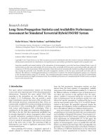
Dedicated indoor systems (Figure 1) can be implemented
using pico- or femtocells, distributed antenna system (DAS),
radiating cables, or optical solutions [5–7]. In a distributed
antenna system, one base station is used to provide service
for large areas via multiple antennas. The base station is
connected to the antennas via splitters, tappers, and coaxial
cables [8]. Since the coverage areas are rather scattered,
and difficult to estimate accurately in indoors, typically
omnidirectional or lightly directional antennas are used with
DAS. Picocell is a base station equipped with an antenna,
typically mounted on the equipment itself, and femtocells are
similar to picocells with smaller transmission power enabling
Tero Isotalo et al.
3
Mother cell
Donor antenna
Repeater
Service antennas
Service antennas
Indoor Node B
Macrocellular
Node B
Macrocellular
Node B
Figure 1: Dedicated indoor system using a dedicated indoor base
station.
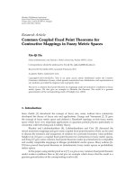
Figure 2: Outdoor-to-indoor repeating.
a very small coverage area for, for example, home/office use.
Radiating cables can be used to provide smooth coverage for
limited areas [9]. Optical solution is an antenna system where
antenna/amplifier units are connected to base station by
optical cables, providing a very flexible system with minimal
cable loss [7].
The benefits of the pico base station are easy installation
and high capacity per antenna unit, whereas DAS requires
antenna cable installation, providing a wide range of coverage from one base station. Earlier studies for DAS with R99
UMTS indicate that the ensuring coverage is the primary rule
for planning, and the enhancement of increasing the antenna
density is rather small [10]. However, similar measurements
for HSDPA indicate that increasing the antenna density
could improve the HSDPA capacity in poor coverage [11].
System simulations for HSDPA DAS systems emphasize the
importance of dedicated indoor systems for ensuring indoor
coverage [12], but verifying measurement results are lacking.
the noise originating from the equipment (repeater and
Node B). The thermal noise density of a single component
can be generally expressed in the form
NTH = kT,
where k is the Boltzmann constant and T is the noise
temperature of a component. The noisy components are
illustrated in Figure 3 in a case with and without repeater.
By using (2) and Figure 3, the combined noise contribution
at Node B becomes
N0 = k Ta + TR GT + k Ta + TB ,
(3)
where Ta is the ambient temperature, and TR and TB are
the noise temperatures of the repeater and base station
equipment. The gain and loss components on the link
between the repeater and the base station are combined into
a parameter
GT = GR ·GD ·LP ·GA .
2.3. Repeaters
Repeaters can be considered as an alternative solution to
the dedicated indoor systems. Outdoor-to-indoor (Figure 2)
repeating can be used to improve coverage in an indoor
environment by exploiting the existing outdoor macrocellular network. The signal from the outdoor network can
be captured using a rooftop antenna and forwarded inside
the building using cables. Furthermore, the received signal
can be amplified before retransmission and the building
penetration loss can be avoided. Single antenna or DAS
can be used indoors to provide the extension in signal
coverage offered by the repeater. Repeaters in this paper
stand for simple bidirectional linear amplifiers that can be
installed in the cell area to provide an amplified replica of
the received UMTS frequency bands. As the whole band
is amplified without signal regeneration, interference from
other UMTS mobiles is included in the amplification process.
Therefore, only out-of-band interference is filtered out.
Repeater amplification ratio (repeater gain) can be adjusted
to tune the effective isotropic radiated power (EIRP) level at
the serving antennas in the downlink.
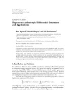
The impact of a repeater on the noise experienced by the
base station receiver can be represented by using effective
noise figure of the base station (EFB ) as presented in [13].
The definition of EFB is based on the thermal noise including
(2)
(4)
In (4), GR is the repeater gain, GD and GA are the antenna
gains of the repeater donor and the Node B, and LP is the
repeater donor link loss. EFB for the total noise contribution
in an unloaded network scenario can now be defined as the
relation of the signal-to-noise ratios between the input and
the output (Figure 3):
EFB =
Sin /Nin W
Sin /kTa
=
Sout /Nout W
Sout / k(Ta + TR )GT + k Ta + TB
(5)
if Sin = Sout and W is the signal bandwidth. Equation (5) can
be then further simplified to form
EFB =
Ta + TB + Ta + TR GT
,
Ta
(6)
which can be reproduced to form
EFB = FB + GT ·FR
(7)
by using the definition for the noise figure [13].
As visualized in (2)–(7), the amount of total noise at
the Node B receiver depends on the noise properties of the
repeater equipment and on the loss and gain components in
4
EURASIP Journal on Wireless Communications and Networking
GD
Repeater
LP
Donor
link
GA
Ta
Node B
TR
Sin
Sout
Nin
GR
Nout
TB
Figure 3: The effective noise figure of the base station can be
calculated taking the ratio of the SNR at the Node B antenna
connector (repeater not installed) and the SNR at the Node B
receiver output.
the donor link. Thus, the repeater configuration (including
the location, gain, and donor antenna properties) affects the
performance of the donor macro cell as well. Thereby, it
is important to consider the effects to the donor macrocell together with the repeater service area performance.
Increased noise level is visible in the uplink noise plus
interference value measured by the base station.
In order to achieve successful repeater operation, the
donor and serving antennas must be placed in a way
that the isolation requirement between the two antennas is
fulfilled. Referring to [14], the isolation between the repeater
donor and serving antenna should be at least 15 dB higher
than the repeater gain. If the isolation is insufficient, selfoscillation (reamplification of the repeater own signal) of
the repeater totally blocks the mother cell. To prevent selfoscillation, automatic gain control (AGC) is implemented in
the repeater to automatically keep the repeater gain at a safe
level.
Some studies have been made considering repeaters as
a method of improving HSDPA performance in indoor
environment. In [15], the performance of outdoor-toindoor repeating was measured in WCDMA Release 99
macrocellular network. The measurements in [15] were
done in a building measuring the signal-to-interference
ratio (SIR) from the primary common pilot channel (PCPICH). The results indicated that the average indoor
SIR level was remarkably improved due to an amplified
signal through repeater. The improved pilot channel SIR
can be seen as improved HSDPA coverage and capacity,
since higher modulation and coding schemes can be utilized.
Furthermore, the indoor HSDPA coverage and capacity have
been studied together with repeaters [16] by system level
simulations. The HSDPA bitrate experienced by the indoor
mobile users was seen to clearly increase together with the
increased repeater gain [16, 17].
3.
MEASUREMENT SETUP
Measurements were performed in a UMTS system, based
on 3GPP Release 5 specification [18]. The network included
a fully functional RNC connected to a core network. The
measurements were performed with two different indoor
systems: a dedicated indoor system (Figure 4(a)), and an
outdoor-to-indoor repeater (Figure 4(b)). Both used HSDPA
capable UMTS Node Bs, connected to a distributed antenna
system either directly or via a donor antenna and an analog
WCDMA repeater. DAS consisted of 1/2 inch feeder cables
connected to omnidirectional antennas with a 2 dBi gain,
and in addition 7/8 inch feeder cables were used with the
repeater. Depending on the serving antenna configuration,
the signal from Node B or repeater was transmitted either
directly to the antenna or split into 3 equal parts. For
the dedicated indoor system, the signal was additionally
attenuated by 30 dB to be able to study HSDPA performance
in a coverage limited network. The relevant parameters of an
indoor system are listed in Table 1.
Measurement equipment consisted of a category 5/6
HSDPA data card [19] with maximum bitrate of 3.6 Mbps
(N = 5, c = 0.75, m = 4, SF = 16 in (1)), connected to a laptop computer, equipped with a WCDMA
field measurement software [20]. The used data card was
calibrated only for commercial use, thus absolute values
of radio channel measurements may include some error.
Therefore, the analysis of the results is mainly based on
relative comparison of the measured scenarios.
In the repeater configuration, the mother cell was a
macro-/microcellular base station equipped with a directional antenna at the height of rooftops. The donor antenna
was a typical macrocellular antenna with a horizontal
beamwidth of 65◦ and a gain of 17.1 dBi [21], installed on
the roof of a building (Figure 5(d)). The donor antenna
was pointed toward the mother cell antenna, located 10◦
off from the mother cell antenna main beam direction.
At the reference repeater configuration, the pilot signal
level difference to the neighboring macrocell measured at
the repeater serving antenna was about 10 dB (ΔP =
RSCPBestCell − RSCP2ndBestCell = 10 dB). Additionally, the
impact of poor repeater location or installation was studied
by misorienting the repeater donor antenna from the mother
cell direction toward a neighboring sector. Then the received
signal code power (RSCP) difference between the serving and
neighboring cell was reduced to about 0 dB (ΔP = 0 dB).
This illustrates the case when repeater is installed on soft or
softer handover region in the network.
The distance between the mother cell antenna and the
repeater donor antenna was about 450 meters. The radio
path between the mother cell and donor antenna was
optically in line of sight, but Fresnel zone of the radio path
was not clear because some trees and rooftops were in the
way. An analog WCDMA repeater [22] with varying gains
(55, 65, and 75 dB) was used to amplify the signal of the
wanted WCDMA frequency band from the donor antenna
in the downlink and from the serving DAS in the uplink
(Figure 4(b)). Relevant parameters of the repeater are listed
in Table 1.
The measurements were carried out in a university
building, representing different environments; a dense office
corridor, a long wide open corridor, and a large open area
in the entrance hall, where approximate room heights
were 2.5 m, 6 m, and 6 m, respectively. 1 antenna and 3
antennas with constant antenna spacing were placed at
the height of 2 m, 4.5 m, and 4.5 m, respectively (Figures
5(b)-5(c)). The measurements were carried out on different
Tero Isotalo et al.
5
RNC
Node
B Attenuation
Service
antennas
Splitter
−30 dB
120 m
+2 dBi
−16.8 dB
−30 dB
HSDPA
UE
95 m
−5 dB
−12.6 dB
+2 dBi
25 m
−4.2 dB
(a)
Node Mother
cell
B
antenna
Repeater
Splitter
Service
antennas
+17.1 35 m +(55, 65,
dBi −2.5 dB 75) dB
RNC
120 m
HSDPA
UE
+2 dBi
−16.8 dB
Donor
antenna
+17.1 35 m +(55, 65, 95 m −5 dB
dBi −2.5 dB 75) dB −12.6 dB
25 m
+2 dBi
−4.2 dB
(b)
Figure 4: System block diagrams and antenna configurations for (a) dedicated indoor system measurements and (b) outdoor-to-indoor
repeater measurements, both with 1 and 3 antenna DASs.
Office corridor
service antenna
Office corridor
route
1st floor
Open area
route
Open corridor
LOS route
2nd floor
(a)
Open area
service antenna
Open corridor
service antenna
(b)
Repeater
donor
antenna
Office corridor
service antennas
2nd floor
Direction
towards
mother
cell
Open area
service antennas
Open corridor
service antennas
5th floor
(c)
(d)
Figure 5: (a) Measurement routes for all indoor and repeater measurements, (b) antenna locations for 1 antenna, (c) 3 antennas, (d) and
repeater donor antenna.
routes, consisting of line-of-sight (LOS) and nonline-ofsight (NLOS) signal paths in open corridor and open area,
and only NLOS in the office corridor (Figure 5(a)). The
measurements were carried out by establishing one HSDPA
data connection and repeating each measurement route
several times. The measurements were done at walking
speed, and the measuring UE was placed on a trolley at height
of one meter. During the measurements, the network was
empty, thus, no other traffic was present. Hypertext transfer
protocol (HTTP) download was used to create traffic on the
downlink, and the measuring UE requested full downlink
throughput (TP).
To indicate coverage and quality of the received radio
signal, typical WCDMA network performance indicators
6
EURASIP Journal on Wireless Communications and Networking
Table 1: System parameters.
Value
Indoor system parameters
Max. total DL power
38
Common pilot channel power
30
Power allocated for HSDPA
5
Repeater parameters
Maximum repeater DL power
35
Maximum repeater UL power
20
Repeater noise figure
3
Repeater donor antenna gain
17.1
Donor antenna beamwidth
65
Unit
dBm
dBm
W
4.1.
dBm
dBm
dB
dBi
deg
as RSCP and received signal strength indicator (RSSI)
were used. RSCP is the received power of P-CPICH after
despreading. RSSI is the total received power over the whole
wideband channel. RSCP indicates purely the coverage of the
cell and
RSCP
EC
=
I0
RSSI
(8)
can be used as a coverage quality indicator, since it takes
into account the noise-and-interference level. With the
used configuration, in empty network and close to Node
B antenna, maximum value of EC /I0 is −3 dB, and after
a user establishes a shared HSDPA connection, EC /I0 is
reduced to −7 dB. Measurement of the HSDPA throughput
on the medium access control layer (MAC) indicates the
available system capacity. MAC throughput corresponds to
physical layer throughput, with constant, approximately 5%
overhead. All the measured throughput values are with one
user and for HSDPA with 5 code transmissions; throughput
per code is one fifth of the presented values. The results
can be converted for 10 codes with rather small error. If the
same power per code is allocated, the available throughput
at the air interface with 10 codes should be theoretically
doubled, but in practice, for example, nonorthogonality
between the codes may cause some error. CQI is not a direct
radio interface measurement, but a vendor-specific value
generated at the mobile, based on, for example, RSCP and
EC /I0 measurements. However, CQI is a useful indicator,
since Node B decides the used modulation and coding
scheme based on mobile CQI reports. Uplink noise plus
interference power level (PNI ) is measured at Node B, which
sends the value to the UE in system information block 7 at
the beginning of each connection. The resolution for the PNI
value reporting is one dBm. Too high PNI is one limiting
factor when maximizing repeater gain. In an empty- or lowloaded network, the impact of the repeater to the uplink load
and system uplink performance is visible in the PNI .
4.
discussing separately different issues risen from macrocellular, outdoor-to-indoor repeater, and dedicated indoor
configurations. Next, the results of the selected scenarios are
studied focusing on the coverage requirements for certain
HSDPA capacities. Lastly, selected examples of raw measurement data are shown to illustrate the system behavior.
MEASUREMENT RESULTS
The measurement results are presented focusing on the
essential observations from the measurement data. First,
averaged results of all measurements (Table 2) are covered,
Indoor coverage from macrocellular network
Since macrocellular networks are a common way for providing indoor coverage, indoor performance of a nearby
outdoor Node B was measured for the reference of comparison. Coverage varied in different indoor locations. In an
office corridor, coverage was poor (mean RSCP −119.1 dBm)
and HSDPA connection could not be established. For open
corridor and open area environment, macrocellular coverage
was better (mean RSCP −104.3 dBm and −101.4 dBm),
providing acceptable or good HSDPA throughput (mean TP
1373 kbps and 1892 kbps), respectively.
4.2.
Outdoor-to-indoor repeater
Based on the measurement results, implementation of an
outdoor-to-indoor repeater enhances significantly indoor
coverage and HSDPA performance. In all environments and
scenarios with a repeater, HSDPA performance is clearly
improved compared to macrocellular. Depending on the
environment, repeater gain GR , and antenna configuration,
pilot coverage was improved by between 13.9 and 41.2 dB,
and HSDPA throughput by between 247 and 1628 kbps
(Table 2).
Increasing the GR has a positive impact on the coverage,
but the challenge in planning is to find out the optimal
value of GR from a system performance point of view.
The minimum required GR for improving the coverage
depends at least on the outdoor and indoor environments,
and the system configuration. The limits for the maximum
repeater gain are set by the repeater equipment, donor and
serving antenna isolation, and uplink received noise plus
interference power (PNI ). The measurements were done with
three different GR s, in 10 dB steps. In the measurements, the
repeater antenna isolation requirement was fulfilled in all
measured configurations. This was resolved by observing the
functionality of the automatic gain control function of the
repeater. Since the increase in the measured average RSCP
values equal approximately to the repeater gain steps (10 dB),
the automatic gain control has not been activated and the
isolation has remained sufficient.
Already the lowest measured GR (55 dB) clearly provides
improved performance in all environments. GR 65 dB provides good performance, and the best HSDPA performance
was always achieved with the highest GR (75 dB). Optimal GR
can be found, when the coverage and capacity requirements
can be met without deteriorating mother cell operation.
PNI in empty network was measured as −105 dBm
(Table 2). Impact of the repeater with GR 55 dB is not yet
visible in the PNI and GR 65 dB increases PNI by one dB,
thus the impact on the mother cell is rather small. With GR
75 dB, PNI has risen by 5 dB to −100 dBm, which already had
Tero Isotalo et al.
7
Table 2: Numerical averaged measurement results.
Gain, GR
Number of service antennas
Macrocellular
Repeater
Repeater
Repeater
Indoor
—
55
65
75
—
Macrocellular
Repeater
Repeater
Repeater
Repeater ΔP = 0dB
Repeater ΔP = 0dB
Repeater ΔP = 0dB
Indoor
—
55
65
75
55
65
75
—
Macrocellular
Repeater
Repeater
Repeater
Indoor
—
55
65
75
—
EC /I0 [dB]
1
3
Office corridor
−119.1
−17.6
−98.7
−97.5
−11.8
−11.4
−90.3
−88.5
−11.0
−10.5
−80.7
−77.9
−10.1
−9.8
−104.5
−101.9
−11.1
−9.2
Open corridor
−104.3
−10.7
−86.3
−83.9
−8.1
−10.5
−77.1
−74.4
−7.6
−10.3
−67.3
−64.5
−7.7
−9.6
−92.9
−89.9
−12.3
−12.3
−83.9
−80.2
−11.6
−11.4
−73.2
−70.3
−11.6
−12.1
−91.1
−95.7
−8.9
−8.7
Open area
−101.4
−13.3
−87.5
−82.9
−11.0
−10.6
−79.5
−73.6
−10.5
−10.6
−69.7
−63.5
−10.3
−10.2
−95.4
−94.7
−8.0
−7.9
RSCP [dBm]
1
3
a significant impact on the available uplink capacity. System
configuration in the uplink from repeater toward the mother
cell has not changed, so the PNI results are the same for
each environment and antenna configuration. From the set
of measured repeater gains, 65 dB is the optimum value, since
the average HSDPA capacity is at a good level (from 2231
to 2948 kbps), but uplink interference has increased by only
one dB. With one outdoor-to-indoor repeater per cell, good
indoor coverage and capacity can be provided without any
deterioration in the mother cell, but limitations may occur if
multiple repeaters are installed under one WCDMA cell.
Antenna misorientation was studied to illustrate the
situation where a repeater is installed in a soft/softer
handover area, or good radio path toward the mother cell is
not available. According to the results, misorientation of the
repeater donor antenna reduces HSDPA indoor performance
significantly. Comparing ΔP = 10 dB to ΔP = 0 dB,
RSCP drops by between 5.9 and 6.8 dB and additional
interference from neighboring cell causes EC /I0 to drop by
between 1.2 and 4.0 dB, resulting in 321 kbps to 1485 kbps
smaller HSDPA throughput values (Table 2) than optimal
donor antenna orientation. This indicates that in repeater
implementation, special attention should be paid to finding
the optimal location and orientation for the repeater donor
antenna.
4.3. Dedicated indoor system
Compared to the repeater serving antenna line, the signal
from indoor Node B was attenuated by 30 dB (Figure 4).
TP [kbps]
1
3
Mean CQI
1
3
n/a
2012
2563
2926
1174
PNI [dBm]
1
3
−105
n/a
2212
2948
2974
1562
15.2
17.1
18.2
12.5
15.9
18.1
18.5
14.7
1373
1818
2566
2231
2871
2173
3001
1497
1553
1579
1633
1450
1516
2315
2043
15.9
16.2
15.5
14.6
15.2
14.6
17.1
10.9
17.0
17.4
17.6
14.2
15.2
13.9
16.4
1892
2139
2416
2640
2895
2879
3007
2260
2313
16.1
17.2
17.7
16.7
15.5
16.7
17.5
18.4
17.0
−105
−105
−104
−104
−100
−100
−105
−105
−105
−105
−105
−104
−104
−100
−100
−105
−105
−104
−104
−99
−99
−105
−105
−105
−105
−105
−104
−104
−100
−100
−105
−105
Thus, the coverage measurements of the repeater and indoor
system are not directly comparable. Attenuation was used in
order to achieve lower average RSCP to emphasize HSDPA
behavior in weaker coverage areas.
Even with a heavily attenuated signal, a dedicated
indoor system is able to provide satisfactory HSDPA performance. Measured mean RSCP values (between −104.5
and −91.1 dBm) are relatively low, but can provide average
HSDPA throughput between 1174 and 2315 kbps. Removing
the 30 dB attenuation would either boost the indoor coverage
by 30 dB or alternatively enable the implementation of a
larger and denser DAS, which indicates very good HSDPA
performance expectations.
Dividing the signal in several antennas, thus increasing
the antenna density, has a clear positive impact on system
coverage and HSDPA capacity. Depending on the environment and scenario, improvement in RSCP was 1–5 dB, and
improvement in HSDPA throughput was 5–30%.
4.4.
HSDPA performance analysis
Based on the measurement results, coverage requirements for
good quality HSDPA performance can be given. The analysis
is based on coverage-capacity mapping of the measurement
results. For all the measurements, corresponding measured
RSCP for each measured throughput sample is collected.
Next, average throughput for each collected RSCP sample
(1 dB accuracy) is calculated. The results of the analysis are
shown in Figures 6–8. Each figure presents separate environment, where the results for macrocellular, indoor, and
8
EURASIP Journal on Wireless Communications and Networking
3500
HSDPA MAC-hs throughput (kbps)
HSDPA MAC-hs throughput (kbps)
3500
3000
2500
2000
1500
1000
500
0
−120
−110
−100
−90
−80
−70
−60
3000
2500
2000
1500
1000
500
0
−50
−120
−110
−100
RSCP (dBm)
Repeater 55 dB 3 antennas
Repeater 65 dB 3 antennas
Repeater 75 dB 3 antennas
Indoor 3 antennas
all repeater configurations are shown. To improve reliability,
RSCP values that have less than about 30 corresponding
throughput samples are discarded.
Measurements for the dedicated indoor system show that
with RSCP −110 dBm, average throughput is at a level from
1200 kbps to 1700 kbps, depending on the environment.
Average throughput increases rather linearly with RSCP up
to −90 dBm, where throughput between 2200 and 2500 kbps
can be achieved.
Measurements with repeaters with a gain between 55 and
75 dB in an office corridor show that at a level of RSCP
−110 dBm, −90 dBm, and −70 dBm, average throughput
of 1600 kbps, between 2700 and 3100 kbps, and 3000 kbps,
respectively, can be achieved (Figure 6). Similarly, in an open
corridor, RSCP −90 dBm and −70 dBm provides average
throughput of 2300 kbps and between 2900 and 3000 kbps,
respectively (Figure 7). In an open area, average throughput
results for RSCP −90 dBm and −70 dBm are 2400 kbps and
between 2800 and 3000 kbps, respectively (Figure 8).
Additionally, measurements of the macrocellular coverage in indoors show that achieved throughput with certain
RSCP is approximately at the same level via a repeater or
from an indoor system. Moreover, it can be noted that from
macrocellular Node B, an average HSDPA throughput of
more than between 2000 and 2500 kbps can be achieved in
indoor locations, where RSCP is above −92 dBm (Figures 7
and 8).
From the results overall, it can be summed up that
RSCP −110 dBm provides average HSDPA throughput above
1000 kbps. Improving the coverage until approximately
RSCP −80 dBm improves HSDPA throughput up to between
2500 and 3000 kbps. Measured average throughput at RSCP
−50 dBm is between 3000 and 3200 kbps, thus improving
coverage above RSCP −80 dBm does not seem to provide
−80
RSCP (dBm)
−70
−60
−50
Macrocellular
Repeater 55 dB 3 antennas
Repeater 65 dB 3 antennas
Repeater 75 dB 3 antennas
Indoor 3 antennas
Figure 7: Average of all TP samples for each RSCP value, open
corridor. Macrocellular, repeater and indoor systems, 3 antenna
configuration.
3500
HSDPA MAC-hs throughput (kbps)
Figure 6: Average of all TP samples for each RSCP value, office
corridor. Repeater and indoor systems, 3 antenna configuration.
−90
3000
2500
2000
1500
1000
500
0
−120
−110
−100
−90
−80
RSCP (dBm)
−70
−60
−50
Macrocellular
Repeater 55 dB 3 antennas
Repeater 65 dB 3 antennas
Repeater 75 dB 3 antennas
Indoor 3 antennas
Figure 8: Average of all TP samples for each RSCP value,
open area. Macrocellular, repeater and indoor systems, 3 antenna
configuration.
clear enhancement in HSDPA throughput, although some
improvement is visible (Figures 7 and 8). The given pilot
coverage thresholds for different average expected HSDPA
throughput values can be used as input for indoor coverage
planning. It has to be noted that the presented coverage thresholds are tied to the used power allocation of
9
−50
−60
−70
−80
−90
−100
−110
−120
30
35
Time (s)
−50
−60
−70
−80
−90
−100
−110
−120
40
5
(a) Macrocellular
−50
−60
−70
−80
−90
−100
−110
−120
15
3.4
3.2
3
2.8
2.6
2.4
2.2
2
1.8
1.6
1.4
1.2
1
0.8
0.6
0.4
0.2
0
−40
20
TP
RSCP
−50
RSCP (dBm)
−40
RSCP (dBm)
20
−30
TP (Mbps)
3.4
3.2
3
2.8
2.6
2.4
2.2
2
1.8
1.6
1.4
1.2
1
0.8
0.6
0.4
0.2
0
10
Time (s)
15
(b) Repeater 55 dB
−30
5
10
Time (s)
−60
−70
−80
−90
−100
−110
−120
15
20
Time (s)
TP (Mbps)
25
−40
RSCP (dBm)
RSCP (dBm)
−40
3.4
3.2
3
2.8
2.6
2.4
2.2
2
1.8
1.6
1.4
1.2
1
0.8
0.6
0.4
0.2
0
−30
TP (Mbps)
3.4
3.2
3
2.8
2.6
2.4
2.2
2
1.8
1.6
1.4
1.2
1
0.8
0.6
0.4
0.2
0
−30
TP (Mbps)
Tero Isotalo et al.
25
TP
RSCP
(c) Indoor
(d) Indoor, not attenuated
Figure 9: Examples from raw measurement data for open area environment, 1 antenna configuration. Captured on the second half of the
measurement route, antenna located on the left hand side.
HSDPA and common pilot channel presented in Table 1,
and also differences between different user equipments can
appear.
4.5. Examples of measurement data
In Figures 9(a)–9(c), illustrative measurement examples of
three different scenarios and additionally one example outside the measurement campaign in Figure 9(d) are presented.
All the examples are screen shots from the measurement
tool, measured in the open area environment with 1
antenna configuration. Each measurement is started below
the antenna, and measured to the end of the measurement
route (except in the macrocellular scenario, where the signal
is coming directly from an outdoor Node B).
In the measurement tool, sampling resolution for RSCP
is 600 milliseconds and for throughput is 200 milliseconds.
In the physical layer, the radio interface indicators are
measured, the CQI is formulated and reported, and the modulation and coding scheme (throughput) is changed every
2 milliseconds (transmission time interval). Thus, the measurement data provided by the measurement tool is roughly
averaged, and the throughput and RSCP do not always correlate perfectly. In macrocellular network (Figure 9(a)), RSCP
varies between −100 dBm and −120 dBm, and throughput
varies between 500 kbps and 1800 kbps.
Figure 9(b) is an example of repeater measurements
with 55 dB repeater gain. While walking away from the
antenna, RSCP drops from −60 dBm to −90 dBm. At RSCP
−60 dBm, throughput repetitively hits the maximum, but
the continuous drops/fades cause the average throughput to
remain below 3000 kbps. When the local average of RSCP
falls below −80 dBm, a small drop is visible in the throughput
curve, but maximum throughput is still reached once in a
while.
Finally, examples of dedicated indoor system measurements are shown. Figure 9(c) illustrates the behavior
of throughput, when RSCP decreases from −80 dBm to
−115 dBm, starting from 3000 kbps, and dropping down
to a level of 2000 kbps. Figure 9(d) shows an example
10
EURASIP Journal on Wireless Communications and Networking
measured with indoor system without the 30 dB attenuation.
Close to the antenna, throughput continuously hits the
maximum, but still fades of radio interface prevent HSDPA
throughput to remain continuously at the maximum value.
This indicates that if continuous maximum throughput is
needed, planning threshold for RSCP should be even above
−50 dBm.
5.
CONCLUSIONS AND DISCUSSION
In the paper, capabilities of an outdoor-to-indoor analog
WCDMA repeater are set against a dedicated indoor system,
and coverage requirements for performance of high-speed
downlink packet access is studied.
In the measured indoor locations, macrocellular outdoor
network provided poor coverage. By implementing an
outdoor-to-indoor repeater or a dedicated indoor system,
the coverage and HSDPA performance in indoor locations
were significantly enhanced. The measurements show that
if certain coverage thresholds can be ensured, an analog
outdoor-to-indoor repeater is able to provide similar HSDPA
performance as a dedicated indoor system. However, with
dedicated indoor system, the coverage requirements are
easier to achieve with higher available transmission power
compared to the repeater.
The measurement results provide basic guidelines for
pilot coverage planning indoors. From an HSDPA performance point of view, improving the coverage provides a clear
benefit up to RSCP −80 dBm, where the average throughput
of at least 2500 kbps (500 kbps per code) was always achieved.
Moreover, for ensuring average throughput values higher
than 3000 kbps (600 kbps per code), RSCP −50 dBm is
needed. Of course, the pilot planning thresholds may change
if different channel power allocations are used.
Increasing the repeater gain improves downlink performance, but already the lowest measured repeater gain clearly
provided improved indoor coverage and capacity. The best
HSDPA indoor performance was achieved with the highest
measured repeater gain, but a high rise in uplink interference
level at the mother cell was caused. Thus, the optimal
repeater gain is a compromise between repeater serving area
performance and mother cell performance.
In addition, the measurements show that misorientation
of the repeater donor antenna reduces HSDPA indoor
performance significantly, and special attention should be
paid to finding an optimal location and orientation for
the repeater donor antenna. Finally, increasing the antenna
density in the serving distributed antenna system has a
clear positive impact on system coverage and HSDPA
capacity.
ACKNOWLEDGMENTS
This work was partly supported by European Communications Engineering, Anite Finland, Elisa, Nokia Siemens Networks, and Nokia. The measurements were partly performed
by Ali Mazhar.
REFERENCES
[1] H. Holma and A. Toskala, Eds., HSDPA/HSUPA for UMTS,
John Wiley & Sons, New York, NY, USA, 2006.
[2] E. Dahlman, S. Parkvall, J. Skă ld, and P. Beming, 3G Evolution:
o
HSPA and LTE for Mobile Broadband, Academic Press, Oxford,
UK, 2007.
[3] S. Aguirre, L. H. Loew, and Y. Lo, “Radio propagation into
buildings at 912, 1920, and 5990 MHz using microcells,” in
Proceedings of the 3rd Annual International Conference on
Universal Personal Communications (ICUPC ’94), pp. 129–134,
San Diego, Calif, USA, September-October 1994.
[4] “Digital Mobile Radio Towards Future Generation Systems,”
COST 231 Final Report, 1998.
[5] S. R. Saunders, Antennas and Propagation for Wireless Communication Systems, John Wiley & Sons, New York, NY, USA,
1999.
[6] Y. P. Zhang, “Indoor radiated-mode leaky feeder propagation
at 2.0 GHz,” IEEE Transactions on Vehicular Technology, vol.
50, no. 2, pp. 536–545, 2001.
[7] Z. Uykan and K. Hugl, “HSDPA system performance of optical
fiber distributed antenna systems in an office environment,” in
Proceedings of the 16th IEEE International Symposium on Personal, Indoor and Mobile Radio Communications (PIMRC ’05),
vol. 4, pp. 23762380, Berlin, Germany, September 2005.
[8] J. Lempiă inen and M. Manninen, Eds., UMTS Radio Network
a
Planning, Optimization and QoS Management, Kluwer Academic Publishers, Dordrecht, The Netherlands, 2003.
[9] C. Seltzer, “Indoor coverage requirements and solutions,” in
Proceedings of IEE Colloquium on Antennas and Propagation
for Future Mobile Communications, pp. 3/1–3/4, London, UK,
February 1998.
[10] T. Isotalo, J. Niemelă , and J. Lempiă inen, “Measurements
a
a
for distributed antennas in WCDMA indoor network,” in
Proceedings of the 9th International Symposium on Wireless
Personal Multimedia Communications (WPMC ’06), pp. 183–
187, San Diego, Calif, USA, September 2006.
[11] T. Isotalo and J. Lempiă inen, HSDPA measurements for
a
indoor DAS, in Proceedings of the 65th IEEE Vehicular
Technology Conference (VTC ’07), pp. 1127–1130, Dublin,
Ireland, April 2007.
[12] K. Hiltunen, B. Olin, and M. Lundevall, “Using dedicated
in-building systems to improve HSDPA indoor coverage and
capacity,” in Proceedings of the 61st IEEE Vehicular Technology
Conference (VTC ’05), vol. 4, pp. 2379–2383, Stockholm,
Sweden, May-June 2005.
[13] R. Anderson, B. Arend, and K. Baker, “Power Controlled
Repeaters for Indoor CDMA Networks,” White paper, Qualcomm Inc., 2003.
[14] “UTRA repeater planning guidelines and system analysis,”
3GPP Technical Specification, TS 25.956, Version 7.1.0,
Release 7.
[15] J. Borkowski, J. Niemelă , T. Isotalo, P. Lă hdekorpi, and J.
a
a
Lempiă inen, “Utilization of an indoor DAS for repeater
a
deployment in WCDMA,” in Proceedings of the 63rd IEEE
Vehicular Technology Conference (VTC ’06), vol. 3, pp. 1112–
1116, Melbourne, Australia, May 2006.
[16] K. Hiltunen, “Using RF repeaters to improve WCDMA
HSDPA coverage and capacity inside buildings,” in Proceedings
of the 17th IEEE International Symposium on Personal, Indoor
and Mobile Radio Communications (PIMRC ’06), pp. 1–5,
Helsinki, Finland, September 2006.
Tero Isotalo et al.
[17] P. Lă hdekorpi, T. Isotalo, A. Mazhar, and J. Lempiă inen,
a
a
Improving HSDPA indoor performance using outdoor
repeater, in Proceedings of the 11th International Symposium on Wireless Personal Multimedia Communications
(WPMC ’08), Lapland, Finland, September 2008.
[18] “High Speed Downlink Packet Access (HSDPA); Overall
description; Stage 2,” 3GPP Technical Specification, TS 25.308,
Version 5.7.0, Release 5.
[19] “UE Radio Access capabilities definition,” 3GPP Technical
Specification, TS 25.306, Version 5.9.0, Release 5.
[20] Anite, “Anite Nemo Outdoor Product description,” 2008,
/>[21] Radio Frequency Systems, “Base station antenna specifications: “RFS APXV206515-7””.
[22] Powerwave technologies (Allgon), “WCDMA channel selective repeater: “AR6560””.
11