Báo cáo hóa học: " Research Article On the Way towards Fourth-Generation Mobile: 3GPP LTE and LTE-Advanced" pptx
Bạn đang xem bản rút gọn của tài liệu. Xem và tải ngay bản đầy đủ của tài liệu tại đây (743.09 KB, 10 trang )
Hindawi Publishing Corporation
EURASIP Journal on Wireless Communications and Networking
Volume 2009, Article ID 354089, 10 pages
doi:10.1155/2009/354089
Research Article
On the Way towards Fourth-Generation Mobile:
3GPP LTE and LTE-Advanced
David Mart
´
ın-Sacrist
´
an, Jose F. Monserrat, Jorge Cabrejas-Pe
˜
nuelas, Daniel Calabuig,
Salvador Garrigas, and Narc
´
ıs Cardona
iTEAM Research Institute, Universidad Politecnica de Valencia, Camino de Vera S/N, 46022 Valencia, Spain
Correspondence should be addressed to Jose F. Monserrat,
Received 31 January 2009; Accepted 18 June 2009
Recommended by Claude Oestges
Long-Term Evolution (LTE) is the new standard recently specified by the 3GPP on the way towards fourth-generation mobile. This
paper presents the main technical features of this standard as well as its performance in terms of peak bit rate and average cell
throughput, among others. LTE entails a big technological improvement as compared with the previous 3G standard. However,
this paper also demonstrates that LTE performance does not fulfil the technical requirements established by ITU-R to classify one
radio access technology as a member of the IMT-Advanced family of standards. Thus, this paper describes the procedure followed
by the 3GPP to address these challenging requirements. Through the design and optimization of new radio access techniques
and a further evolution of the system, the 3GPP is laying down the foundations of the future LTE-Advanced standard, the 3GPP
candidate for 4G. This paper offers a brief insight into these technological trends.
Copyright © 2009 David Mart
´
ın-Sacrist
´
an et al. This is an open access article distributed under the Creative Commons Attribution
License, which permits unrestricted use, distribution, and reproduction in any medium, provided the original work is properly
cited.
1. Introduction
In the last years, technology evolution in mobile communi-
cations is mainly motivated by three relevant agents: (1) the
market globalization and liberalization and the increasing
competence among vendors and operators coming from this
new framework, (2) the popularization of IEEE 802 wireless
technologies within the mobile communications sector and,
finally, (3) the exponential increase in the demand for
advanced telecommunication services.
Concerning the last item, the envisaged applications to
be supported by current and future cellular systems include
Voice over IP (VoIP), videoconference, push-to-talk over
cellular (PoC), multimedia messaging, multiplayer games,
audio and video streaming, content download of ring tones,
video clips, Virtual Private Network (VPN) connections,
web browsing, email access, File Transfer Protocol (FTP).
All these applications can be classified in several ways based
on the Quality of Service (QoS) treatment that they require.
Some of them are real-time and delay-sensitive, like voice and
videoconference, while some others require integrity, high
data-rate, and are sensitive to latency (like VPN and FTP).
The simultaneous support of applications with different
QoS requirements is one of the most important challenges
that cellular systems are facing. At the same time, the
spectrum scarcity makes that new wideband cellular systems
are designed with very high spectral efficiency.
It is precisely that this increasing market demand and its
enormous economic benefits, together with the new chal-
lenges that come with the requirements in higher spectral
efficiency and services aggregation, raised the need to allocate
new frequency channels to mobile communications systems.
That is why the ITU-R WP 8F started in October 2005 the
definition of the future Fourth-Generation Mobile (4G), also
known as International Mobile Telecommunications (IMTs)
Advanced, following the same model of global standard-
ization used with the Third Generation, IMT-2000. The
objective of this initiative is to specify a set of requirements
in terms of transmission capacity and quality of service,
in such a way that if a certain technology fulfils all these
requirements it is included by the ITU in the IMT-Advanced
set of standards. This inclusion firstly endorses technologies
and motivates operators to invest in them, but furthermore
it allows these standards to make use of the frequency bands
2 EURASIP Journal on Wireless Communications and Networking
specially designated for IMT-Advanced, what entails a great
motivation for mobile operators to increase their offered
services and transmission capacity.
The race towards IMT-Advanced was officially started in
March 2008, when a Circular Letter was distributed asking
for the submission of new technology proposals [1]. Previous
to this official call, the 3rd Partnership Project (3GPP)
established the Long Term Evolution (LTE) standardization
activity as an ongoing task to build up a framework for
the evolution of the 3GPP radio technologies, concretely
UMTS, towards 4G. The 3GPP divided this work into two
phases: the former concerns the completion of the first LTE
standard (Release 8), whereas the latter intends to adapt
LTE to the requirements of 4G through the specification
of a new technology called LTE-Advanced (Release 9 and
10). Following this plan, in December 2008 3GPP approved
the specifications of LTE Release 8 which encompasses
the Evolved UTRAN (E-UTRAN) and the Evolved Packet
Core (EPC). Otherwise, the LTE-Advanced Study Item was
launched in May 2008, expecting its completion in October
2009 according to the ITU-R schedule for the IMT-Advanced
process. In the meantime, research community has been
called for the performance assessment of the definitive LTE
Release 8 standard.
Actually, several papers deal with the performance evalu-
ation of LTE. However, up to date this assessment has been
partially done because of one of these two reasons. First,
some of these works only focused on the physical layer,
leaving out the retransmission processes and error correction
[2–4]. System level analysis needs MAC layer performance
information and cannot be carried out with only a physical
layer characterization. Second, other papers assessing the
performance of LTE radio access network assumed ideal
channel estimation, which results in an optimistic estimation
of LTE capacity [5–7].
This paper describes the main characteristics of LTE
Release 8 and evaluates LTE link level performance consid-
ering a transmission chain fully compliant with LTE Release
8 and including realistic HARQ and turbo-decoding. Besides,
the capacity of LTE systems is analyzed in terms of maximum
achievable throughput and cell capacity distribution in a
conventional scenario. These studies allow having a rough
idea on the benefits and capabilities of the new standard.
Finally, this paper offers an overview of the current research
trends followed by 3GPP in the definition process of LTE-
Advanced thus foreseeing the main characteristics of next
generation mobile.
2. LTE
3GPP Long Term Evolution is the name given to the new
standard developed by 3GPP to cope with the increasing
throughput requirements of the market. LTE is the next
step in the evolution of 2G and 3G systems and also in
the provisioning of quality levels similar to those of current
wired networks.
3GPP RAN working groups started LTE/EPC standard-
ization in December 2004 with a feasibility study for an
evolved UTRAN and for the all IP-based EPC. This is known
as the Study Item phase. In December 2007 all LTE func-
tional specifications were finished. Besides, EPC functional
specifications reached major milestones for interworking
with 3GPP and CDMA networks. In 2008 3GPP working
groups were running to finish all protocol and performance
specifications, being these tasks completed in December 2008
hence ending Release 8.
2.1. LTE Requirements. 3GPP collected in [8] the require-
ments that an evolved UTRAN should meet. Some of the
requirements are defined in an absolute manner while other
requirements are defined in relation to UTRA performance.
It is worth to mention that for the UTRA baseline it is
considered the use of Release 6 HSDPA with a 1
× 1
multiantenna scheme for the downlink and Release 6 HSUPA
with a 1
× 2 multiantenna scheme in uplink. For the sake of
comparison, in LTE it is considered transmission using up
to 2
× 2 antennas in downlink and up to 1 × 2 antennas in
uplink.
Among others, LTE design targets are the following.
(i) The system should support peak data rates of
100 Mbps in downlink and 50 Mbps in uplink within
a 20 MHz bandwidth or, equivalently, spectral effi-
ciency values of 5 bps/Hz and 2.5 bps/Hz, respec-
tively. Baseline considers 2 antennas in UE for
downlink and 1 antenna in UE for uplink.
(ii) Downlink and uplink user throughput per MHz at
the 5% point of the CDF, 2 to 3 times Release 6 HSPA.
(iii) Downlink averaged user throughput per MHz, 3
to 4 times Release 6 HSDPA. Uplink averaged
user throughput per MHz, 2 to 3 times Release 6
Enhanced Uplink.
(iv) Spectrum efficiency 3 to 4 times Release 6 HSDPA
in downlink and 2 to 3 times Release 6 HSUPA in
uplink, in a loaded network.
(v) Mobility up to 350 km/h.
(vi) Spectrum flexibility, seamless coexistence with previ-
ous technologies and reduced complexity and cost of
the overall system.
2.2. LTE Release 8 Technical Ove rview. To meet these require-
ments, a combination of a new system architecture together
with an enhanced radio access technology was incorporated
in the specifications.
2.2.1. Architecture. There are different types of functions in
a cellular network. Based on them, network can be split into
two parts: a radio access network part and a core network
part. Functions like modulation, header compression and
handover belong to the access network, whereas other
functions like charging or mobility management are part of
the core network. In case of LTE, the radio access network is
E-UTRAN and the core network EPC.
Radio Access Network. The radio access network of LTE
is called E-UTRAN and one of its main features is that
EURASIP Journal on Wireless Communications and Networking 3
all services, including real-time, will be supported over
shared packet channels. This approach will achieve increased
spectral efficiency which will turn into higher system capacity
with respect to current UMTS and HSPA. An important
consequence of using packet access for all services is the
better integration among all multimedia services and among
wireless and fixed services.
The main philosophy behind LTE is minimizing the
number of nodes. Therefore the developers opted for a
single-node architecture. The new base station is more
complicated than the Node B in WCDMA/HSPA radio access
networks, and is consequently called eNB (Enhanced Node
B). The eNBs have all necessary functionalities for LTE
radio access network including the functions related to radio
resource management.
Core Network. The new core network is a radical evolution
of the one of third generation systems and it only covers
the packet-switched domain. Therefore it has a new name:
Evolved Packet Core.
Following the same philosophy as for the E-UTRAN, the
number of nodes is reduced. EPC divides user data flows into
the control and the data planes. A specific node is defined
for each plane plus the generic gateway that connects the
LTE network to the internet and other systems. The EPC
comprises several functional entities.
(i) The MME (Mobility Management Entity): is respon-
sible for the control plane functions related to
subscriber and session management.
(ii) The Serving Gateway: is the anchor point of the
packet data interface towards E-UTRAN. Moreover,
it acts as the routing node towards other 3GPP
technologies.
(iii) The PDN Gateway (Packet Data Network): is the
termination point for sessions towards the external
packet data network. It is also the router to the
Internet.
(iv) The PCRF (Policy and Charging Rules Function):
controls the tariff making and the IP Multimedia
Subsystem (IMS) configuration of each user.
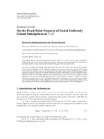
The overall structure of LTE is shown in Figure 1.
2.2.2. Radio Access Fundamentals. The most important
technologies included in the new radio access network
are Orthogonal Frequency Division Multiplexing (OFDM),
multidimensional (time, frequency) dynamic resource allo-
cation and link adaptation, Multiple Input Multiple Output
(MIMO) transmission, turbo coding and hybrid Automatic
Repeat reQuest (ARQ) with soft combining. These technolo-
gies are shortly explained in the following paragraphs.
OFDM. Orthogonal Frequency Division Multiplexing is a
kind of multicarrier transmission technique with a relatively
large number of subcarriers. OFDM offers a lot of advan-
tages. First of all, by using a multiple carrier transmission
technique, the symbol time can be made substantially longer
Internet
PDN GW
eNB
MME/serving GW
S5 interface
S1 interface
X2 interface
Figure 1: LTE Release 8 architecture.
than the channel delay spread, which reduces significantly
or even removes the intersymbol interference (ISI). In other
words, OFDM provides a high robustness against frequency
selective fading. Secondly, due to its specific structure,
OFDM allows for low-complexity implementation by means
of Fast Fourier Transform (FFT) processing. Thirdly, the
access to the frequency domain (OFDMA) implies a high
degree of freedom to the scheduler. Finally, it offers spectrum
flexibility which facilitates a smooth evolution from already
existing radio access technologies to LTE.
In the FDD mode of LTE each OFDM symbol is trans-
mitted over subcarriers of 15 or 7.5 kHz. One subframe
lasts 1 ms, divided in two 0.5 ms slots, and contains several
consecutive OFDM symbols (14 and 12 for the 15 and
7.5 kHz modes, resp.).
In the uplink, Single Carrier Frequency Division Multiple
Access (SC-FDMA) is used rather than OFDM. SC-FDMA
is also known as DFT-spread OFDM modulation. Basically,
SC-FDMA is identical to OFDM unless an initial FFT is
applied before the OFDM modulation. The objective of
such modification is to reduce the peak to average power
ratio, thus decreasing the power consumption in the user
terminals.
Multidimensional Dynamic Resource Allocation and Link
Adaptation. In LTE, both uplink and downlink transmission
schemes can assign smaller, nonoverlapping frequency bands
to the different users, offering frequency division multi-
ple access (FDMA). This assignment can be dynamically
adjusted in time and is referred to as scheduling. Accordingly,
the LTE resources can be represented as a time-frequency
grid. The minor element of this grid is called resource
4 EURASIP Journal on Wireless Communications and Networking
element and consists of one subcarrier during an OFDM
symbol. However, the minor LTE resource allocation unit is
the resource block that consists of 12 subcarriers during one
slot.
Link adaptation is closely related to scheduling and deals
with how to set the transmission parameters of a radio link
to handle variations of the radio-link quality. This is achieved
in LTE through adaptive channel coding and adaptive
modulation. Specifically, in LTE available modulations are
QPSK, 16QAM and 64QAM, whilst coding rate can take
values from a lower edge of around 0.07 up to 0.93.
MIMO. One of the most important means to achieve
the high data rate objectives for LTE is multiple antenna
transmission. In LTE downlink it is supported one, two or
four transmit antennas in the eNB and one, two or four
receive antennas in the UE. Multiple antennas can be used in
different ways: to obtain additional transmit/receive diversity
or to get spatial multiplexing increasing the data rate by
creating several parallel channels if conditions allow to.
Nevertheless, in LTE uplink although one, two or four receive
antennas are allowed in the eNB, only one transmitting
antenna is allowed in the UE. Therefore, multiple antennas
can be only used to obtain receive diversity.
Turbo Coding. In order to correct bit errors, introduced by
channel variations and noise, channel coding is utilized. In
case of the LTE downlink shared channel (DL-SCH) a turbo
encoder with rate 1/3 is used, followed by a rate matching to
adapt the coding rate to the desired level. In each subframe
of 1 ms, one or two (with multicodeword MIMO) codewords
can be coded and transmitted.
Hybrid ARQ with Soft Combining. Hybrid ARQ with soft
combining is a technique that deals with the retransmission
of data in case of errors. In an ARQ scheme, the receiver
uses an error-detecting code to check if the received packet
contains errors or not. The transmitter is informed by a
NACK or ACK respectively. In case of a NACK, the packet
is retransmitted.
A combination of forward error correction (FEC) and
ARQ is known as hybrid ARQ. Most practical hybrid ARQ
schemes are built around a CRC code for error detection and
a turbocode for error correction, as it is the case of LTE.
In hybrid ARQ with soft combining, the erroneously
received packet is stored in a buffer and later combined with
the retransmission(s) to obtain a single packet that is more
reliable than its constituents. In LTE full incremental redun-
dancy (IR) is applied, which means that the retransmitted
packets are typically not identical with the first transmission
but carry complementary information.
2.3. Analysis of LTE Per formance. Different methods can be
used to assess the performance of a mobile technology. Each
method is best suited for a particular kind of performance
assessment. For instance, analytical methods or inspections
are valid to evaluate peak data rates or peak spectral
efficiencies. However, a deeper performance analysis requires
the usage of simulation. Simulators are usually divided in
two classes: link level simulators and system level simulators.
Link level simulators are used to emulate the transmission of
information from a unique transmitter to a unique receiver
modeling the physical layer with high precision. They include
models for coding/decoding, MIMO processing, scrambling,
modulation, channel, channel estimation and equalization,
and so forth. System level simulators emulate the operation
of a network with a number of cells and several users per cell.
In this kind of simulators, higher level functions are included
for call admission control, scheduling, power control, and so
forth, while link to system level models is used to facilitate
the emulation of each radio link. This section presents some
results obtained from both types of simulators.
In the course of the LTE standardization process, the
3GPP conducted several deep evaluations of the developing
technology to ensure the achievement of requirements. With
this aim, a feasibility study for E-UTRA and E-UTRAN
was carried out in the 3GPP. Reference framework for the
performance analysis is set by two documents [9, 10], to
ensure the comparability of the different results. Mean LTE
performance results obtained by the 3GPP partners are
included in [11] where the results are also compared to
the requirements. Results shown in that document are a
summary of those in [12, 13] that collect the results of all the
partners. In this assessment the used scenarios are similar to
those used by the 3GPP to allow comparability of results.
This assessment allows getting an insight into to which
extent LTE implies a revolution in comparison with UMTS.
As shown in next section, LTE results demonstrate that this
technology is quite close to the requirements established for
the Fourth-Generation mobile, although further improve-
ments are expected in LTE-Advanced.
2.3.1. Peak Spectral Efficiency. Thepeakspectralefficiency is
the highest theoretical data rate assignable to a single mobile
user divided by the allocated bandwidth. The highest data
rate is calculated as the received data bits assuming error-free
conditions and excluding radio resources that are used for
control issues and guard bands. At the end, the radio access
technology is classified as more or less powerful according
to the achievable efficiency what makes this measurement
perfect for comparative purposes.
Assuming a transmission bandwidth of 20 MHz the
maximum achievable rates in downlink are: 91.2 Mbps for
SIMO 1
× 2, 172.8 Mbps for MIMO 2 × 2 and 326.4 Mbps
for MIMO 4
× 4. The resulting peak spectral efficiencies are
4.56, 8.64 and 16.32 b/s/Hz for the considered multiantenna
schemes. These values have been calculated taking into
account realistic overhead due to the reference signals and
assuming that control signals overhead is equal to one
OFDM symbol in each subframe. In uplink with SIMO
1
× 2themaximumachievablerateis86.4Mbpswitha
transmission bandwidth of 20 MHz. Thus, the peak spectral
efficiency is 4.32 b/s/Hz. These values have been calculated
assuming that two OFDM symbols are occupied by reference
signals. Both in downlink and uplink calculations 64QAM is
the considered modulation and code rate is assumed to be 1.
EURASIP Journal on Wireless Communications and Networking 5
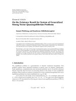
The calculated peak spectral efficiencies of LTE are
depicted in Figure 2 for both downlink and uplink together
with the efficiencies of UMTS Release 6, that is, including
HSDPA and HSUPA. From this peak spectrum efficiency
it can be seen that LTE with 20 MHz meets and exceeds
the 100 Mbps downlink and 50 Mbps uplink initial targets.
Besides, the comparison with UMTS demonstrates that LTE
is a major step forward in mobile radio communications.
With these achievable data rates mobile systems will give
a greater user experience with the capability of supporting
more demanding applications.
2.3.2. LTE Link Level Performance. Based on link level
simulations it can be assessed the relation between effective
throughput (correctly received bits per time unit) and signal-
to-noise plus interference ratio (SINR). Simulations assessed
for this paper used 10 MHz of bandwidth for both downlink
and uplink. This bandwidth is equivalent to 50 LTE resource
blocks. The evaluation was focused on the performance
experienced by a pedestrian user and hence the user mobility
model used was the extended pedestrian A model [14]with
a Doppler frequency of 5 Hz. The central frequency has
been set to 2.5 GHz, the most likely band for initial LTE
deployment. The set of modulation and coding schemes
has been selected from the CQI table included in LTE
specifications [15]. This set was selected by 3GPP to cover
the LTE SINR dynamic margin with approximately 2 dB steps
between consecutive curves. A distinction from other studies
is that channel estimation was realistically calculated at the
receivers. In order to exploit the multiantenna configuration
at the receiver side, minimum mean-square error (MMSE)
equalization was considered. The remaining parameters
considered in the simulations are summarized in Ta bl e 1.
Concerning LTE downlink, different multiantenna con-
figurations were modeled including SIMO 1
×2, MIMO 2×2
and MIMO 4
× 4. Simulated MIMO scheme followed the
open loop spatial multiplexing scheme as specified by the
3GPP [16], the number of codewords was 2 and the number
of layers was equal to the number of transmit antennas, that
is, 2 and 4. Additionally, the multiple channels among anten-
nas were supposed uncorrelated. Control channel and signals
overhead were taken into account and hence the first two
OFDM symbols in each subframe were reserved for control
channels. Besides, reference signals were emulated in detail,
although neither broadcast information nor synchronization
signals overhead was considered.
In the uplink, two different multiantenna configurations
were simulated: SIMO 1
× 2 and SIMO 1 × 4. The multiple
channels among antennas were supposed uncorrelated too.
Nowadays, the LTE standard does not allow MIMO in uplink
so that MIMO schemes were not simulated. Therefore,
as established in the 3GPP specifications [17], only one
codeword was considered. Moreover, 12 of the 14 available
SC-FDMA symbols in a subframe were occupied by codified
data since the other 2 were reserved for reference signals
needed for the channel estimation at the receiver.
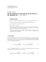
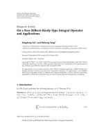
Taking into account these assumptions and parameters,
a set of simulations was performed whose results are shown
in Figure 3 for LTE downlink and in Figure 4 for LTE
uplink. In both figures it can be observed that the maximum
throughputs are not equal to the peak throughputs previ-
ously calculated. The reason is threefold: the used bandwidth
is not 20 MHz but 10 MHz, the highest coding rate used is
0.93 instead of 1 and downlink control signals overhead is
assumed to be 2 OFDM symbols instead of 1.
In LTE downlink, according to the results shown in
Figure 3,MIMO4
× 4schemeprovidesaclearlybetter
performance than the other schemes for almost all the
useful SINR margin. Nevertheless, MIMO 2
×2schemedoes
not provide an important performance improvement until
SINR reaches a value of 15 dB. Also, it can be observed
that improvement factor in peak throughput due to MIMO
schemes is far from being equal to the number of antennas (2
or 4). Instead, peak throughput is multiplied by 1.7 and 3.6
in MIMO 2
×2andMIMO4×4 respectively. This is basically
due to the higher quantity of reference signals needed in the
MIMO schemes.
In LTE uplink, there is not any peak throughput gain
when using more receiver antennas. But a nonnegligible
SINR gain can be achieved. This gain is about 5 dB for a
throughput of 20 Mbps. Note that in SIMO 1
× 4maximum
rate is achieved 10 dB before than in SIMO 1
×2.
2.3.3. LTE System Level Performance. LTE performance anal-
ysis at system level requires the definition of system level
statistics. The cell spectral efficiency and the cell edge user
spectral efficiency are the more important ones. Given a
multiuser/multicell scenario, the cell spectral efficiency is
defined as the aggregate throughput of all users (the number
of correctly received bits over a certain period of time)
normalized by the overall cell bandwidth and divided by
the number of cells. In the same scenario, the cell edge
user spectral efficiency is the 5% point of CDF of the user
throughput normalized with the overall cell bandwidth.
In order to calculate these values in the downlink, a
dynamic system level simulator has been used. The main
parameters of the considered scenario are shown in Ta ble 1 .
The scenario is similar to the “Case 1” scenario in [9]. The
main differences in this assessment are that the channel has
been implemented using a tapped delay line model and a low
correlation among channels has been assumed. Specifically,
anETUchannelhasbeenused[14]. The scheduler operation
follows the proposal of [18] where scheduling algorithm is
divided in two parts: one for the time domain and another
for the frequency domain. For both domains a proportional
fair approach has been used.
Following the proposed approach, average cell spectral
efficiency in downlink was obtained yielding 1.52 bps/Hz/cell
for SIMO 1
× 2, 1.70 bps/Hz/cell for MIMO 2 × 2and
2.50 bps/Hz/cell for MIMO 4
× 4.Thecelledgeuser
spectral efficiencies are 0.02 bps/Hz/user, 0.03 bps/Hz/user
and 0.05 bps/Hz/user, for the same antenna configurations.
Note that the LTE values for the uplink have been extracted
from the results presented by the 3GPP partners in [12],
since the downlink values obtained in this assessment fit
with 3GPP results. Since LTE requirements were defined as
6 EURASIP Journal on Wireless Communications and Networking
Peak spectral efficiency (bps/Hz)
0
2
4
6
8
10
12
14
16
18
UMTS R6
LTE SIMO
1
×2
LTE SIMO
2 ×2
LTE SIMO
4 ×4
(a)
Peak spectral efficiency (bps/Hz)
0
0.5
1
1.5
2
2.5
3
3.5
4
4.5
5
UMTS R6 LTE
(b)
Figure 2: LTE peak spectral efficiencies in downlink (a) and uplink (b).
Table 1: Simulation parameters.
Common parameters
Bandwidth 10 MHz (50 RB)
Channel Tapped delay line: EPA with 5 Hz Doppler frequency at link level, ETU at system level
Central frequency 2.5 GHz
MCS CQI 1–15
Multiantenna schemes
DL SIMO 1
×2, MIMO 2 ×2/4 ×4
UL SIMO 1
×2/1 ×4
Control channels overhead
DL 2 OFDM symbols per subframe
UL Not considered
System level parameters
Inter site distance (ISD) 500 m
Cell deployment 3-sector cells, reuse 1
Pathloss 130.2+37.6 log 10 (d(km)) dB
Shadowing lognormal, σ
= 8dB
eNB transmission power 46 dBm
Noise spectral density
−174 dBm/Hz
Scheduler Proportional Fair in time and frequency domains up to 5 UEs is scheduled per subframe
Mobility Users moving at 30 km/h
relative to HSPA performance, Ta bl e 2 includes HSPA figures
extracted also from [12, 13]. After direct inspection, it can be
concluded that most of the requirements specified by 3GPP
are fulfilled by the current Release 8 version of LTE.
3. LTE-Advanced and
the Fourth-Generation Mobile
The process of defining the future IMT-Advanced family
was started with a Circular Letter issued by ITU-R calling
for submission of candidate Radio Interface Technologies
(RITs) and fvcandidate sets of Radio Interface Technologies
(SRITs) for IMT-Advanced [1]. However, all documents
available in that moment concerning IMT-Advanced did
not specify any new technical details about the properties
of future 4G systems. Instead, they just reference the
Recommendation M.1645 [19], in which the objectives of
the future development of IMT-Advanced family were barely
defined:toreach100Mb/sformobileaccessandupto1Gb/s
for nomadic wireless access. Unfortunately, it was not until
November 2008 when the requirements related to technical
performance for IMT-Advanced candidate radio interfaces
were described [20].
Just after receiving the Circular Letter, the 3GPP orga-
nized a workshop on IMT-Advanced where the following
decisions were made.
(i) LTE-Advanced will be an evolution of LTE. Therefore
LTE-Advanced must be backward compatible with
LT E Re l e as e 8 .
(ii) LTE-Advanced requirements will meet or even exceed
IMT-Advanced requirements following the ITU-R
agenda.
(iii) LTE-Advanced should support significantly increased
instantaneous peak data rates in order to reach
ITU requirements. Primary focus should be on low
mobility users. Moreover, it is required a further
improvement of cell edge data rates.
EURASIP Journal on Wireless Communications and Networking 7
Table 2: LTE requirements related to technical performance.
Requirements LTE TR
25.913
LTE simulation results
Peak data rate (Gbps)
0.1
0.172 (2
×2)
0.326 (4
×4)
Latency
C-Plane < 100 ms
U-Plane < 5ms
—
Peak spectral efficiency
(bps/Hz)
DL 5 (1 ×2)
4.56 (1
×2)
8.64 (2
×2)
16.32 (4
×4)
UL 2.5 (1
×2) 4.32 (1 ×2)
Average spectral efficiency
(bps/Hz/cell)
DL
EUTRA (2
×2)
3-4 times
HSDPA R6
{0.53}
1.52 (1 ×2)
1.70 (2
×2)
2.50 (4
×4)
UL
EUTRA (1
×2)
2-3 times
HSUPA R6 (1
×2)
{0.332}
0.73 (1 ×2)
Cell edge user spectral
efficiency (bps/Hz/cell/user)
DL
EUTRA (2
×2)
2-3 times
HSDPA R6
{0.02}
0.02 (1 ×2)
0.04 (2
×2)
0.05 (4
×4)
UL
EUTRA (1
×2)
2-3 times
HSUPA R6 (1
×2)
{0.009}
0.02 (1 ×2)
Mobility
Up to 350 km/h 30 km/h
Bandwidth
Up to 20 MHz 10 MHz
Table 3: IMT-Advanced requirements related to LTE-Advanced requirements.
Requirement ITU-R
M.2134
Requirements LTE-A
TR 36.913
Peak data rate (Gbps)
1
1-(DL)
0.5-(UL)
Latency
C-Plane < 100 ms
U-Plane < 10 ms
C-Plane < 50 ms
U-Plane < 5ms
Peak spectral efficiency
(bps/Hz)
DL 15 (4
×4) 30 (8 ×8)
UL 6.75 (2
×4) 15 (4 ×4)
Cell spectral efficiency
(bps/Hz/cell)
DL 2.2 (4 ×2)
2.4 (2
×2)
2.6 (4
×2)
3.7 (4
×4)
UL 1.4 (2
×4)
1.2 (1
×2)
2.0 (2
×4)
Cell edge user spectral
efficiency
(bps/Hz/cell/user)
DL 0.06 (4
×2)
0.07 (2
×2)
0.09 (4
×2)
0.12 (4
×4)
UL 0.03 (2
×4)
0.04 (1
×2)
0.07 (2
×4)
Mobility
Up to 350 km/h Up to 350 km/h
Bandwidth
>40 MHz Up to 100 MHz
8 EURASIP Journal on Wireless Communications and Networking
Effective throughput (Mbps)
0
20
40
60
80
100
120
140
SINR (dB)
−20 −10 0 10 20 30 40
SIMO 1
×2
MIMO 2
×2
MIMO 4
×4
Figure 3: Link level evaluation of throughput versus SINR in LTE
downlink.
Effective throughput (Mbps)
0
5
10
15
20
25
30
35
40
45
SINR (dB)
−20 −10 0 10 20 30
SIMO 1
×2
SIMO 1
×4
Figure 4: Link level evaluation of throughput versus SINR in LTE
uplink.
With these clear objectives, and without knowing the final
technical requirements yet, 3GPP defined a bullets list
with the first requirements for LTE-Advanced and some
technical proposals. Besides, it was decided to officially
gather and approve them in the technical report TR 36.913
[21]. The remaining of this section deals with both aspects:
requirements and technical proposals for LTE-Advanced.
3.1. LTE-Advanced Requirements. The requirement specifi-
cation list was also included in TR 36.913. Although it is
expected a list extension, these are some of the current
agreements on the requirements for LTE-Advanced [21].
(i) Peak data rate of 1 Gbps for downlink (DL) and
500 Mbps for uplink (UL).
(ii) Regarding latency, in the C-plane the transition time
from Idle to Connected should be lower than 50 ms.
In the active state, a dormant user should take less
than 10 ms to get synchronized and the scheduler
should reduce the U-plane latency at maximum.
(iii) The system should support downlink peak spectral
efficiency up to 30 bps/Hz and uplink peak spectral
efficiency of 15 bps/Hz with an antenna configuration
of 8
×8orlessinDLand4×4orlessinUL.
(iv) The 3GPP defined a base coverage urban scenario
with intersite distance of 500 m and pedestrian
users. Assuming this scenario, average user spec-
tral efficiency in DL must be 2.4 bps/Hz/cell with
MIMO 2
× 2, 2.6 bps/Hz/cell with MIMO 4 × 2and
3.7 bps/Hz/cell with MIMO 4
× 4, whereas in UL
the target average spectral efficiency is 1.2 bps/Hz/cell
and 2.0 bps/Hz/cell with SIMO 1
×2andMIMO2×4,
respectively.
(v) In the same scenario with 10 users, cell edge user
spectral efficiency will be 0.07 bps/Hz/cell/user in DL
2
× 2, 0.09 in DL 4 × 2 and 0.12 in DL 4 × 4. In
the UL, this cell edge user spectral efficiency must be
0.04 bps/Hz/cell/user with SIMO 1
×2 and 0.07 with
MIMO 2
×4.
(vi) The mobility and coverage requirements are identical
to LTE Release 8. There are only differences with
indoor deployments that need additional care in LTE-
Advanced.
(vii) In terms of spectrum flexibility, the LTE-Advanced
system will support scalable bandwidth and spectrum
aggregation with transmission bandwidths up to
100 MHz in DL and UL.
(viii) LTE-Advanced must guarantee backward compatibil-
ity and interworking with LTE and with other 3GPP
legacy systems.
Ta bl e 3 summarizes the list of requirements established by
ITU-R and 3GPP allowing a direct comparison among
4G and LTE-Advanced. According to this table, it can be
concluded that LTE-Advanced is being designed to be a
strong candidate for next 4G, since it fulfils or even exceeds
all IMT-Advanced requirements.
3.2. LTE-Advanced Technical Proposals. LT E Re l ea s e 8 c an
already fulfill some of the requirements specified for IMT-
Advanced systems. However, it is also clear that there are
more challenging requirements under discussion in the
3GPP, which would need novel radio access techniques and
system evolution. The 3GPP working groups, mainly RAN1
working on the physical layer, are currently evaluating some
techniques to enhance LTE Release 8 performance. This
section offers an overview of some of these proposals.
Support of Wider Bandwidth. A significant underlying fea-
ture of LTE-Advanced will be the flexible spectrum usage.
EURASIP Journal on Wireless Communications and Networking 9
The framework for the LTE-Advanced air-interface technol-
ogy is mostly determined by the use of wider bandwidths,
potentially even up to 100 MHz, noncontiguous spectrum
deployments, also referred to as spectrum aggregation, and
a need for flexible spectrum usage.
In general OFDM provides a simple means to increase
bandwidth: adding additional subcarriers. Due to the discon-
tinuous spectrum reserved for IMT-Advanced, the available
bandwidth might also be fragmented. Therefore, the user
equipments should be able to filter, process and decode
such a large variable bandwidth. The increased decoding
complexity is one of the major challenges of this wider
bandwidth.
Concerning the resource allocation in the eNB and the
backward compatibility, minimum changes in the specifica-
tions will be required if scheduling, MIMO, Link Adaptation
and HARQ are performed over groups of carriers of 20 MHz.
For instance, a user receiving information in 100 MHz
bandwidth will need 5 receiver chains, one per each 20 MHz
block.
Coordinated Multiple Point Transmission and Reception.
Coordinated multi point transmission and reception are
considered for LTE-Advanced as one of the most promising
techniques to improve data rates, hence increasing average
cell throughput. It consists in coordinating the transmission
and reception of signal from/to one UE in several geograph-
ically distributed points. So far, the discussions have focused
on classifying the different alternatives and identifying their
constraints. Potential impact on specifications comprises
three areas: feedback and measurement mechanisms from
the UE, preprocessing schemes and reference signal design.
Relaying Functionality. Relaying can be afforded from three
different levels of complexity. The simplest one is the Layer
1 relaying, that is, the usage of repeaters. Repeaters receive
the signal, amplify it and retransmit the information thus
covering black holes inside cells. Terminals can make use of
the repeated and direct signals. However, in order to combine
constructively both signals there should be a small delay, less
than the cyclic prefix, in their reception.
In Layer 2 relaying the relay node has the capability of
controlling at least part of the RRM functionality. In some
slots the relay node acts as a user terminal being in the
subsequent slot a base station transmitting to some users
located close to the relay.
Finally, Layer 3 relaying is conceived to use the LTE radio
access in the backhaul wireless connecting one eNB with
another eNB that behaves as a central hub. This anchor eNB
routes the packets between the wired and wireless backhaul,
acting like an IP router.
Enhanced Multiple-Input Multiple-Output Transmission.
Another significant element of the LTE-Advanced technology
framework is MIMO, as in theory it offers a simple way to
increase the spectral efficiency. The combination of higher
order MIMO transmission, beamforming or MultiUser
(MU) MIMO is envisaged as one of the key technologies for
LT E -A dv a nc e d .
In case of spectrum aggregation, the antenna correlation
may be different in each spectrum segment given a fixed
antenna configuration. Therefore, in LTE-Advanced one
channel element may encompass both low correlation and
high correlation scenarios simultaneously. Since MU-MIMO
is more appropriated for high correlation scenarios than
Single-User (SU) MIMO, to fully utilize the characteristics
of different scattering scenarios both SU-MIMO and MU-
MIMO should be simultaneously used.
4. Conclusions
LTE has been designed as a future technology to cope
with next user requirements. In this paper two complete
LTE Release 8 link and system level simulators have been
presented together with several performance results. Based
on these results, this paper concludes that LTE will offer peak
rates of more than 150 Mbps in the downlink and 40 Mbps in
the uplink with 10 MHz bandwidth. Besides, in the downlink
the minimum average throughput will be around 30 Mbps,
which represents a quite significant improvement in the
cellular systems performance. As compared with current
cellular systems, LTE entails an enhancement of more than
six times the performance of HSDPA/HSUPA.
This paper has also given an initial insight into the
new technical proposals currently under discussion in the
framework of 3GPP. This analysis allows those who are
interested in wireless communications to get aligned with the
research community towards the definition and optimization
of next Fourth-Generation mobile.
Acknowledgments
Part of this work has been performed in the framework of
the CELTIC Project CP5-026 WINNER+. This work was
supported by the Spanish Ministry of Science under the
Project TEC2008-06817-C02-01/TEC.
References
[1] ITU-R Circular Letter 5/LCCE/2, “Invitation for submission
of proposals for candidate radio interface technologies for
the terrestrial components of the radio interface(s) for IMT-
Advanced and invitation to participate in their subsequent
evaluation,” March 2008.
[2]J.J.S
´
anchez, D. Morales-Jim
´
enez, G. G
´
omez, and J. T.
Enbrambasaguas, “Physical layer performance of long term
evolution cellular technology,” in Proceedings of the 16th
IST Mobile and Wireless Communications Summit, pp. 1–5,
Budapest, Hungary, July 2007.
[3] A. Osman and A. Mohammed, “Performance evaluation of a
low-complexity OFDM UMTS-LTE system,” in Proceedings of
the IEEE Vehicular Technology Conference (VTC ’08), pp. 2142–
2146, Singapore, May 2008.
[4] K. Manolakis, A. Ibing, and V. Jungnickel, “Performance
evaluation of a 3GPP LTE terminal receiver,” in Proceedings
of the 14th European Wireless Conference (EW ’08), pp. 1–5,
Prague, Czech Republic, June 2008.
10 EURASIP Journal on Wireless Communications and Networking
[5] C. Spiegel, J. Berkmann, Z. Bai, T. Scholand, and C. Drewes,
“MIMO schemes in UTRA LTE, a comparison,” in Proceedings
of the IEEE Vehicular Technology Conference (VTC ’08),pp.
2228–2232, Singapore, May 2008.
[6] N. Wei, A. Pokhariyal, C. Rom, et al., “Baseline E-UTRA
downlink spectral efficiency evaluation,” in Proceedings of the
IEEE Vehicular Technology Conference (VTC ’06), pp. 2131–
2135, Montreal, Canada, September 2006.
[7]P.Mogensen,W.Na,I.Z.Kov
´
acs, et al., “LTE capacity
compared to the shannon bound,” in Proceedings of the 65th
IEEE Vehicular Technology Conference (VTC ’07), pp. 1234–
1238, Dublin, Ireland, April 2007.
[8] 3GPP TR 25.913, “Requirements for Evolved UTRA (E-
UTRA) and Evolved UTRAN (E-UTRAN),” v.8.0.0, December
2008.
[9] 3GPP TR 25.814, “Physical layer aspects for evolved Universal
Terrestrial Radio Access (UTRA),” September 2006.
[10] 3GPP R1-070674, “LTE physical layer framework for perfor-
mance evaluation,” February 2007.
[11] 3GPP TR 25.912, “Feasibility Study for evolved Universal
Terrestrial Radio Access (UTRA) and Universal Terrestrial
Radio Access Network (UTRAN),” v.8.0.0, December 2008.
[12] 3GPP R1-072261, “LTE Performance Evaluation—Uplink
Summary,” May 2007.
[13] 3GPP R1-072578, “Summary of Downlink Performance Eval-
uation,” May 2007.
[14] 3GPP TS 36.101, “User Equipment (UE) radio transmission
and reception,” v.8.5.1, March 2008.
[15] 3GPP TS 36.213, “Physical layer procedures,” v.8.6.0, March
2009.
[16] 3GPP TS 36.211, “Long Term Evolution physical layer; General
description,” v.8.6.0, March 2009.
[17] 3GPP TS 36.212, “Multiplexing and channel coding,” v.8.6.0,
March 2009.
[18] G. Monghal, K. I. Pedersen, I. Z. Kov
´
acs, and P. E. Mogensen,
“QoS oriented time and frequency domain packet schedulers
for the UTRAN long term evolution,” in Proceedings of the 67th
IEEE Vehicular Technology Conference (VTC ’08), pp. 2532–
2536, May 2008.
[19] ITU-R Recommendation M.1645, “Framework and overall
objectives of the future development of IMT-2000 and systems
beyond IMT-2000,” June 2003.
[20] ITU-R Report M.2134, “Requirements related to technical
performance for IMT-Advanced radio interface(s),” Novem-
ber 2008.
[21] 3GPP TR 36.913, “Requirements for Further Advancements
for E-UTRA,” v.8.0.1, March 2009.