Báo cáo hóa học: "Preparation of Aligned Ultra-long and Diameter-controlled Silicon Oxide Nanotubes by Plasma Enhanced Chemical Vapor Deposition Using Electrospun PVP Nanofiber Template" potx
Bạn đang xem bản rút gọn của tài liệu. Xem và tải ngay bản đầy đủ của tài liệu tại đây (539.85 KB, 7 trang )
NANO EXPRESS
Preparation of Aligned Ultra-long and Diameter-controlled
Silicon Oxide Nanotubes by Plasma Enhanced Chemical Vapor
Deposition Using Electrospun PVP Nanofiber Template
Ming Zhou
•
Jinyuan Zhou
•
Ruishan Li
•
Erqing Xie
Received: 14 July 2009 / Accepted: 27 October 2009 /Published online: 19 November 2009
Ó to the authors 2009
Abstract Well-aligned and suspended polyvinyl pyrroli-
done (PVP) nanofibers with 8 mm in length were obtained
by electrospinning. Using the aligned suspended PVP
nanofibers array as template, aligned ultra-long silicon
oxide (SiOx) nanotubes with very high aspect ratios have
been prepared by plasma-enhanced chemical vapor depo-
sition (PECVD) process. The inner diameter (20–200 nm)
and wall thickness (12–90 nm) of tubes were controlled,
respectively, by baking the electrospun nanofibers and by
coating time without sacrificing the orientation degree and
the length of arrays. The micro-PL spectrum of SiOx
nanotubes shows a strong blue–green emission with a peak
at about 514 nm accompanied by two shoulders around 415
and 624 nm. The blue–green emission is caused by the
defects in the nanotubes.
Keywords Electrospinning Á PECVD Á SiOx nanotubes Á
TUFT process
Introduction
Since the discovery of carbon nanotubes in 1991 [1], much
effort has been focused on the synthesis of other inorganic
tubular nanomaterials, such as MoS
2
, BN, TiO
2
,VO
X
and
GaN [2–6]. Nowadays, various inorganic nanotubes have
attracted more and more interests in the nanomaterial
research [7, 8]. Nanotubes of inorganic materials like silica,
which do not have sp
2
bonding that favors tube formation,
were generally prepared using porous materials [9, 10]or
wire-shaped materials as templates [11]. However, once
these templates were removed, the tubes would generally
bundle up and become less oriented, even be damaged.
Considerable efforts have also been made to prepare
aligned silica nanotube arrays to improve their function-
ality in advanced thin film devices. Fan et al. [12] have
developed a process to transformed silicon nanowire arrays
into silica nanotube arrays through a thermal oxidation-
etching approach. Li et al. [13] have synthesized ultra-long
and well-aligned silica nanotubes by the VLS (In as cata-
lyst) mechanism lately. These SiO
2
nanotubes are of spe-
cial interest because of their potential applications in
bioanalysis, bioseparation, optical device and catalysis.
Compared with the insulating SiO
2
nanotubes, the silicon
monoxide (SiO) nanotubes are predicted to be semicon-
ducting and proposed to have prospective applications in
the semiconductor and catalysis industries [14, 15].
Although the studied SiO nanotubes are very thin and only
of triangular, tetragonal, pentagonal and hexagonal cross-
sections considered, the study suggested a possible route to
tailor the electronic structures of silicon oxide (SiOx)
nanotubes. Meanwhile, the investigation of PL mechanism
of SiOx nanotubes have important significance because the
room temperature PL of porous Si [16, 17] and Si-ion-
implanted SiO
2
(SiO
2
:Si
?
)[18, 19] has stimulated com-
prehensive studies on light-emitting devices made from
Si-based materials. So far, reports of producing SiOx
nanotubes are still very much lacking [20].
Electrospinning is a simple and highly efficient tech-
nique to produce long and extremely fine polymer fiber
using an electrostatically repulsive force and an electric
field between two electrodes to apply a high voltage to a
polymer solution or melt [21, 22]. Meanwhile, different
from other nano fiber fabrication processes, electrospinning
M. Zhou Á J. Zhou Á R. Li Á E. Xie (&)
Key Laboratory For Magnetism and Magnetic Materials of the
Ministry of Education, Lanzhou University, 730000 Lanzhou,
People’s Republic of China
e-mail: ;
123
Nanoscale Res Lett (2010) 5:279–285
DOI 10.1007/s11671-009-9476-6
has the ability to form various fiber assemblies [23, 24]. So
the approach of using electrospun polymer fibers as tem-
plates [25–27] provides great versatility for the design of
tubular materials with controlled dimensions. In this work,
the preparation of aligned ultra-long and the synthesis of
diameter-controlled SiOx nanotubes array by plasma-
enhanced chemical vapor deposition (PECVD) process
using electrospun-suspended polymer fiber array as tem-
plate are reported. The morphology and chemical compo-
sitions of SiOx nanotubes were characterized by scanning
electron microscope, transmission electron microscope
equipped with energy-dispersive X-ray, X-ray photoelec-
tron spectroscopy and micro-Raman. The micro-photolu-
minescence spectrum was also measured to investigate the
luminescence mechanism of SiOx nanotubes.
Experimental
Poly(vinyl pyrrolidone) (PVP, 0.18 g, M
w
& 1 300 000,
Sigma–Aldrich) was dissolved in ethanol (3 ml) to form a
7 wt% solution, then loaded to a glass syringe equipped
with a stainless steel needle with an inner diameter of
0.34 mm. The needle was connected to a high-voltage
supply capable of generating DC voltage up to 60 kV. The
voltage for electrospinning was kept at 18 kV. Two pieces
of stainless steel stripes with an air gap of 8 mm were
placed 18 cm below the tip of the needle [24]. Assisted by
electrostatic interactions, the nanofibers were stretched
across the gap to form a parallel array. A stainless steel
U-shaped frame with a distance of 4 mm between two
branches was used to transfer the aligned nanofibers by
vertically moving through the gap. The U-shaped frame
with suspended nanofiber array span across its two bran-
ches was left in dry oven with temperature ranging from 80
to 150°C for 8–10 h to make the PVP template fibers
thinner. And then it was transferred to the reaction cham-
ber. The PECVD system is capacitively coupled using a
radio frequency (13.56 MHz). After the chamber was
pumped down to 3.0 9 10
-3
Pa, the pre-treatment of
template fibers for surface activation was conducted by the
H
2
gas and Ar gas injected into the chamber for 10 min.
The applied radio frequency power was 60 W. Then, silane
gas with the concentration of 2% flowed into the chamber
for the coating. The deposition pressure was 130 Pa. After
coating, the aligned core–shell nanofibers were transferred
to the surface of silicon wafer by vertically moving silicon
wafer through the gap of U-shape frames. Finally, the
aligned core–shell nanofibers array was heated at 800°C for
2 h in high-purity argon gas (99.999%) to remove the PVP
core, which led to nanotubes array.
The morphology of aligned nanotubes was observed by
field emission scanning electron microscope (FE-SEM,
Hitachi S-4800) and transmission electron microscope
(TEM, JEM-2010, 200 kV). Chemical compositions of the
nanotubes were detected using an energy-dispersive spec-
trometer (EDS) attached to the TEM, X-ray photoelectron
spectroscopy (XPS, VG ESCALAB 210) using Mg Ka
radiation and micro-Raman (JY-HR800) with a yttrium
aluminum garnet (YAG) laser (532 nm). Furthermore, the
micro-photoluminescence (PL) spectrum was measured
with a He–Cd laser (325 nm) at room temperature.
Results and Discussion
The selection of the core polymer to be used as the nano-
fiber template is critical to the process. Polyvinyl pyrroli-
done (PVP, M
w
& 1,300,000) was selected as a suitable
template material since it could be processed to fibers with
length in the millimeter range, and be stable during coating
but degrade under conditions to leave the wall material
intact. The equilibrium melting temperature of PVP is
300°C[28], which makes the template fiber thermome-
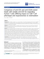
chanically stable. Figure 1 shows a SEM image of the
aligned PVP nanofibers on a silicon substrate. The enlarged
view, shown in the inset, indicates that the average diam-
eter of PVP nanofibers with smooth surface is 200 nm.
Figure 2a is a digital image showing the aligned core–shell
nanofibers coated by PECVD suspended across the
U-shaped frame. The PVP nanofibers were baked from
80 to 150°C for 8–10 h and coated for 6–15 min, but it still
kept suspended and tight with a length of 4 mm, indicating
that PVP has good thermal and mechanical stability. Fig-
ure 2b is optical micrograph of suspended aligned core–
shell nanofiber array from one of the samples shown in
Fig. 2a. From Figs. 1 and 2, it was clearly that well-aligned
and ultra-long PVP nanofibers were obtained by electros-
pinning over large areas. There are two basic requirements
Fig. 1 SEM image of aligned PVP nanofibers. The inset is their
enlarged view
280 Nanoscale Res Lett (2010) 5:279–285
123
for obtaining highly aligned PVP nanofibers in this process:
(i) the jet emerging from the Talylor’s cone is stabilized in
the effect of electric field; (ii) choosing a suitable gap
width and a suitable needle tip-to-target distance. More-
over, the density of the nanofiber array depends on the
electrospinning time.
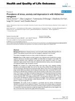
Figure 3a and b show, respectively, low-magnification
and high- magnification SEM images of the well-aligned
nanotubes, which were obtained after PVP nanofibers were
baked at 80°C for 10 h, coated for 10 min and removed by
annealing. Most of the nanotubes are straight and have
uniform dimensions along their entire lengths. The average
outer diameter of the nanotubes is around 170 nm and the
surface of nanotubes is smooth. The tubular structures are
clearly shown in Fig. 3c. The SEM image of a cross-
section of nanotubes reveals that the coating layer did not
collapse after PVP template nanofibers were removed by
pyrolysis.
Because the nanotubes are aligned and ultra long, it can
be physically separated by a simple scratch and put on
copper grid without carbon film for TEM observations,
which allow us to gain an insight into the prepared tube
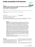
structure. Figure 4a and b show, respectively, the TEM
images of aligned nanotubes and an individual nanotube
prepared in the same condition. There is a distinct
boundary between the tube channel and tube wall, and
some remainder of PVP pyrolysis is in the tubes channel.
The average inner diameter of the nanotubes is approxi-
mately 110 nm, which is thinner than the average diameter
of electrospun PVP nanofibers. The wall thickness of
nanotubes is about 30 nm uniformly corresponding to a
Fig. 2 a Digital image and b optical micrographs of the aligned
core–shell nanofibers suspended over the U-shaped frame
Fig. 3 a Low-magnification and b high-magnification SEM images
of aligned SiOx nanotubes. c SEM image of a cross-section of SiOx
nanotubes
Nanoscale Res Lett (2010) 5:279–285 281
123
10-min coating time. The highly diffusive ring pattern in
the corresponding selected-area electron diffraction
(SAED) taken from the individual nanotube reveals these
tubular materials are amorphous (inset in Fig. 4b). Fig-
ure 4c gives EDX spectrum of the individual nanotube
shown in Fig. 4b. Leaving out account Cu from copper
TEM grid, the atomic components of the nanotube are
Si
28.07
,O
34.36
and C
37.57
. The result suggests that silicon
oxide SiOx nanotubes are obtained. The additional carbon
peak in the spectrum arises from remainder of PVP pyro-
lysis [28], which is consistent with the observation in TEM
image (Fig. 4a). Considering that the SiOx nanotubes are
ultra-long and have a smooth tube wall, part of PVP core
should be removed through the tube opening, which is also
a reasonable answer for question from Liu et al. [27].
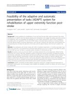
Using plastic flake as substrate, the XPS of samples pre
and postannealing were obtained. The XPS measurements
of the specimen surfaces (* 5 nm in depth) indicate that
these samples contain Si, O and C. The Si (2p) spectra of
samples pre and postannealing are shown in Fig. 5a and b,
respectively. According to the random-bonding model,
many group analyzed the Si 2p core-level spectra in terms
of five chemically shifted components corresponding to
Fig. 4 a TEM image of aligned SiOx nanotubes. b TEM image of an
individual SiOx nanotube. Inset the SAED rings taken from the
nanotube. c EDX spectrum taken from the SiOx nanotube shown in
(b)
Fig. 5 Fitting analysis of Si 2p core-level spectra of samples a pre
and b postannealing
282 Nanoscale Res Lett (2010) 5:279–285
123
basic Si bonding units Si–(Si
4-n
O
n
), with n = 0, 1,…, 4
[29–32]. A curve-fitting procedure of the Si 2p core-level
line was also adopted in order to identify the inequivalent
states of Si. In Fig. 5a, two peaks situated at 99.2 and
102.4 eV are associated with the Si
0
(Si-Si
4
) and Si
3?
(Si-
SiO
3
), respectively. By contrast, two peaks situated at
102.1 and 103.5 eV are associated with Si
3?
(Si-SiO
3
) and
Si
4?
(Si-O
4
), respectively (shown in Fig. 5b). The disap-
pearance of Si
0
(Si-Si
4
) and appearance of Si
4?
(Si-O
4
)
indicate that the sample is slightly oxidized in the
annealing process and thin SiO
2
layers are formed on the
surface of SiOx nanotubes. This result is unexpected, but it
also indicates that the SiOx nanotubes can be oxidized
completely to SiO
2
by heating the nanotubes in oxygen or
air, which is similar to oxidation of SiOx film reported by
Gonzalez-Elipe et al. [31].
Figure 6 is the micro-Raman spectrum of SiOx nano-
tubes. There is no Si peak in the spectrum, indicating that
no silicon particles exist in the tube wall. The D- and
G-peaks of graphite at 1,358 and 1,618 cm
-1
still arise
from the remainder of PVP pyrolysis in the tube channel,
which is consistent with observation in TEM image and
measured results of EDS and XPS.
Generally, the inner diameters of tubes represented the
diameters of the polymer template fibers [25]. However, it
was found that the average inner diameter (110 nm)
(Fig. 4b) of SiOx nanotubes was smaller than the average
diameter (200 nm) (Fig. 1) of electrospun PVP nanofibers.
We deduced that the electrospun PVP nanofibers became
fine because of the baking by oven (80°C for 10 h) and
plasma etching in the pre-treatment process similar to
electron irradiation [33], which led to a smaller inner
diameter of nanotubes. To confirm the effect of baking,
electrospun PVP template fibers were dried at 150°C for
3 h and at 80°C for 5 h subsequently. TEM images of the
sample coated for 6 min are shown in Fig. 7a and b. It can
be clearly seen that the average inner diameter of aligned
nanotubes is 20 nm, and the wall thickness is about 12 nm,
which demonstrates that the diameter of PVP nanofibers or
the inner diameter of nanotubes can be controlled by
simply baking electrospun PVP fibers. Although the inner
diameter of the nanotubes can also be tuned by control of
the diameter of template fiber by simply adjusting the
physical properties of polymer solution, this usually be-
geted changes of the solution conductivity further influ-
enced the orientation degree of polymer fibers in spinning
process. Moreover, thinner fibers tended to be broken
during the spinning process. Therefore, baking offered a
simple and effective approach for controlling the diameter
of electrospun polymer fibers without sacrificing the ori-
entation degree and the length of arrays. Since the inner
diameter of SiOx nanotubes decreased, some remainder of
PVP pyrolysis was difficult to remove and existed in the
tube channel in the form of nanofibers, shown in Fig. 7b.
Drying electrospun PVP nanofibers at 80°C for 10 h and
prolonging coating time to 15 min increased outer diam-
eter of SiOx tube to 300 nm with 90-nm-thick wall, as
showing by SEM in Fig 7c and d. The increase of wall
thickness would naturally enhance the mechanical prop-
erties of the tubes. Because the PVP nanofibers were
suspended in the form of alignment in the dissociated gas
and had suitable packing density, the thickness of the
coated layers was uniform and had a wide varying range.
Therefore, the outer diameter of the tubes is governed by
the thickness of the tube wall controlled by the CVD
conditions (in particular by the coating time), whereas the
inner diameter is controlled by the size of the PVP tem-
plate fibers.
Figure 8 presents the micro-PL spectrum of the SiOx
nanotubes. Strong blue–green emission from the SiOx
nanotubes, with at least two peaks at 400–600 nm region
was observed. After decomposing with multi-Gaussian
function, three luminescent centers at 415, 514 and 624 nm
with spectra linewidths of 57, 106 and 157 nm, respec-
tively, are demonstrated. The strongest PL peak at 514 nm
is very similar to those obtained by Jiang et al. [20] and Yu
et al. [34]. The luminescence at 514 nm reported by Lin
et al. [19, 35] has been attributed to the E
0
d
defect
(a paramagnetic state of Si cluster or a delocalized variant
of the E
0
center). Some observations also suggest that the
E
0
d
defect is based on the existence of small amorphous Si
cluster [36, 37] or its precursor [38] in SiO
2
:Si
?
or Si:O
?
materials, which agrees quite well with the measured
results of EDS and XPS. Based on the literature data [19,
35, 39], the luminescence at 415 and 620 nm are identified
as originating from the weak oxygen bond (WOB) defect
Fig. 6 Raman spectrum of SiOx nanotubes
Nanoscale Res Lett (2010) 5:279–285 283
123
and the nonbridging oxygen hole center (NBOHC) defect,
respectively.
Conclusions
In summary, it has been shown that aligned ultra-long SiOx
nanotubes can be prepared by PECVD system using elec-
trospun aligned PVP template fiber array. The inner
diameter and wall thickness of nanotubes were con-
trolled,respectively, by baking the electrospun PVP
nanofibers and by coating time without sacrificing the
orientation degree and the length of arrays. The PL spec-
trum of SiOx nanotubes shows a blue–green emission with
a peak at about 514 nm accompanied by two shoulders
around 415 and 624 nm, which is caused by the defects in
the nanotubes. Our method shows a great improvement on
the basis of tubes by fiber templates (TUFT) process [25]
and is a straightforward and easy process for preparing
aligned ultra-long SiOx nanotubes with very high aspect
ratios. These aligned and diameter-controlled SiOx nano-
tubes obtained by us are of great potential for use in
nanoscale fluidic bioseparation, sensing, catalysis and
nanodevices. Moreover, this method can be used for
Fig. 7 a Low-magnification and b high-magnification TEM images of aligned SiOx nanotubes with thinner inner diameter. c Low-
magnification and d high-magnification SEM images of a cross-section of SiOx nanotubes with thicker tube wall
Fig. 8 Micro-PL spectrum of SiOx nanotubes
284 Nanoscale Res Lett (2010) 5:279–285
123
preparation of aligned hybrid tubes and nesting structure of
nanoparticle/nanofiber/nanotube in tube.
Acknowledgments This work was financially supported by the
Program for New Century Excellent Talents in University of China
(Grant No: NCET-04-0975).
References
1. S. Iijima, Nature 354, 56 (1991)
2. Y. Feldman, E. Wasserman, D.J. Srolovitch, R. Tenne, Science
267, 222 (1995)
3. N.G. Chopra, R.J. Luyken, K. Cherry, V.H. Crespi, M.L. Cohen,
S.G. Louie, A. Zettl, Science 269, 966 (1995)
4. P. Hoyer, Langmuir 12, 1411 (1996)
5. M.E. Spahr, P. Bitterli, R. Nesper, M. Mu
¨
ller, F. Krumeich,
H.U. Nissen, Angew. Chem. Int. Ed. Engl. 37, 1263 (1998)
6. J. Goldberger, R. He, Y. Zhang, S. Lee, H. Yan, H. Chol,
P. Yang, Nature 422, 599 (2003)
7. X. Sun, Y. Sun, J. Mater. Sci. Technol. 24, 569 (2008)
8. R. Tenne, Nat. Nanotechnol. 1, 103 (2006)
9. M. Zhang, E. Ciocan, Y. Bando, K. Wada, L.L. Cheng, P. Pirouz,
Appl. Phys. Lett. 80, 491 (2002)
10. N.I. Kovtyukhova, T.E. Mallouk, T.S. Mayer, Adv. Mater. 15,
780 (2003)
11. Y.D. Yin, Y. Lu, Y.G. Sun, Y.N. Xia, Nano Lett. 2, 427 (2002)
12. R. Fan, Y. Wu, D. Li, M. Yue, A. Majumdar, P. Yang, J. Am.
Chem. Soc. 125, 5254 (2003)
13. Y.B. Li, Y. Bando, D. Golberg, Adv. Mater. 16, 37 (2004)
14. A.K. Singh, V. Kumar, Y. Kawazoe, Phys. Rev. B 72, 155422
(2005)
15. M.W. Zhao, R.Q. Zhang, Y.Y. Xia, J. Appl. Phys. 102, 024313
(2007)
16. G.G. Qin, Y.Q. Jia, Solid State Commun. 86, 559 (1993)
17. G.G. Qin, X.S. Liu, S.Y. Ma, J. Lin, G.Q. Yao, X.Y. Lin,
K.X. Lin, Phys. Rev. B 55, 12876 (1997)
18. H.Z. Song, X.M. Bao, Phys. Rev. B 55, 6988 (1997)
19. G.R. Lin, C.J. Lin, K.C. Yu, J. Appl. Phys. 96, 3025 (2004)
20. Z. Jiang, T. Xie, X.Y. Yuan, B.Y. Geng, G.S. Wu, G.Z. Wang,
G.W. Meng, L.D. Zhang, Appl. Phys. A 81, 477 (2005)
21. Y. Dzenis, Science 304, 1917 (2004)
22. D. Li, Y. Xia, Adv. Mater. 16, 1151 (2004)
23. W.E. Teo, S. Ramakrishna, Nanotechnology 17, 89 (2006)
24. D. Li, Y. Wang, Y. Xia, Nano Lett. 3, 1167 (2003)
25. M. Bognitzki, H. Hou, M. Ishaque, T. Frese, M. Hellwig,
C. Schwarte, A. Schaper, J.H. Wendorff, A. Greiner, Adv. Mater.
12, 637 (2000)
26. R.A. Caruso, J.H. Schattka, A. Greiner, Adv. Mater. 13, 1577
(2001)
27. W. Liu, M. Graham, E.A. Evans, D.H. Reneker, J. Mater. Res. 17,
3206 (2002)
28. H. Schmiers, J. Friebel, P. Streubel, R. Hesse, R. Kopsel, Carbon
37, 1965 (1999)
29. F.G. Bell, L. Ley, Phys. Rev. B 37, 8383 (1988)
30. T.P. Nguyen, S. Lefrant, J. Phys.: Condens. Matter 1, 5197 (1989)
31. A. Barranco, F. Yubero, J.P. Espinos, J.P. Holgado, A. Caballero,
A.R. Gonzalez-Elipe, J.A. Mejias, Vacuum 67, 491 (2002)
32. S.M.A. Durrani, M.F. Al-Kuhaili, E.E. Khawaja, J. Phys.: Con-
dens. Matter 15, 8123 (2003)
33. H.G. Duan, E.Q. Xie, L. Han, Z. Xu, Adv. Mater. 20, 3284 (2008)
34. Z.G. Bai, D.P. Yu, J.J. Wang, Y.H. Zou, W. Qian, J.S. Fu,
S.Q. Feng, J. Xu, L.P. You, Mater. Sci. Eng. B. 72, 117 (2000)
35. G.R. Lin, C.J. Lin, C.K. Lin, L.J. Chou, Y.L. Chueh, J. Appl.
Phys. 97, 094306 (2005)
36. P. Mutti, G. Ghislotti, S. Bertoni, L. Bonoldi, G.F. Cerofolini,
L. Meda, E. Grilli, M. Guzzi, Appl. Phys. Lett. 66, 851 (1995)
37. H. Takagi, H. Owada, Y. Yamazaki, A. Ishizaki, T. Nakagiri,
Appl. Phys. Lett. 56, 2379 (1990)
38. L.T. Canham, Appl. Phys. Lett. 57, 1046 (1990)
39. J.C. Cheang-Wong, A. Oliver, J. Roiz, J.M. Hernandez,
L. Rodrigues-Fernandez, J.G. Morales, A. Crespo-Sosa, Nucl.
Instrum. Methods Phys. Res. B 175–177, 490 (2001)
Nanoscale Res Lett (2010) 5:279–285 285
123