Báo cáo hóa học: "Friction and Shear Strength at the Nanowire–Substrate Interfaces" pdf
Bạn đang xem bản rút gọn của tài liệu. Xem và tải ngay bản đầy đủ của tài liệu tại đây (310.9 KB, 5 trang )
NANO EXPRESS
Friction and Shear Strength at the Nanowire–Substrate Interfaces
Yong Zhu
•
Qingquan Qin
•
Yi Gu
•
Zhong Lin Wang
Received: 6 September 2009 / Accepted: 28 October 2009 / Published online: 28 November 2009
Ó to the authors 2009
Abstract The friction and shear strength of nanowire
(NW)–substrate interfaces critically influences the electri-
cal/mechanical performance and life time of NW-based
nanodevices. Yet, very few reports on this subject are
available in the literature because of the experimental
challenges involved and, more specifically no studies have
been reported to investigate the configuration of individual
NW tip in contact with a substrate. In this letter, using a new
experimental method, we report the friction measurement
between a NW tip and a substrate for the first time. The
measurement was based on NW buckling in situ inside a
scanning electron microscope. The coefficients of friction
between silver NW and gold substrate and between ZnO NW
and gold substrate were found to be 0.09–0.12 and 0.10–0.15,
respectively. The adhesion between a NW and the substrate
modified the true contact area, which affected the interfacial
shear strength. Continuum mechanics calculation found that
interfacial shear strengths between silver NW and gold
substrate and between ZnO NW and gold substrate
were 134–139 MPa and 78.9–95.3 MPa, respectively. This
method can be applied to measure friction parameters of
other NW–substrate systems. Our results on interfacial
friction and shear strength could have implication on the
AFM three-point bending tests used for nanomechanical
characterisation.
Keywords Nanowire Á Interface Á Friction Á
Shear strength Á Nanomechanics
Introduction
In nanodevices, nanowires (NWs) are typically integrated
to larger structures. The NW–substrate interfaces therefore
play a critical role in both mechanical reliability and
electrical performance of these nanodevices, especially
when the size of the NW is small [1, 2]. Such interfaces
include two configurations, NW length or NW tip in con-
tact with the substrate, and both configurations have a wide
range of applications. For example, the tip-substrate con-
tacts are present in nanogenerators [3], nanostructured solar
cells [4], atomic force microscopy (AFM) with carbon
nanotube (CNT) tips [5], CNT tapes [6] and many other
nanodevices. Indeed, as recently outlined by Wang [7], one
critical future direction for nanogenerator research is study
of the NW–metal interface to build a robust, low wearing
structure for improving the device lifetime.
Experimental work on NW interfacial mechanics has
been limited so far due to experimental challenges at the
nanoscale [8] and the fact that many existing tribology
tools such as AFM, surface force apparatus (SFA), quartz
microbalance and microfabricated devices cannot be
readily applied [9, 10]. Static friction force between NWs
(including CNTs) and substrates was estimated from the
highly deformed shapes of NWs [11]. Recently CNTs were
found to slip on silicon oxide surface at a lateral force of 8
nN [12], and ZnO NWs to slip on silicon surface at a few
lN[13]. However, the above studies on friction are only
Y. Zhu (&) Á Q. Qin
Department of Mechanical and Aerospace Engineering, North
Carolina State University, Raleigh, NC 27695, USA
e-mail:
Y. Gu
Department of Physics, Washington State University, Pullman,
WA 99164, USA
Z. L. Wang
School of Materials Science and Engineering, Georgia Institute
of Technology, Atlanta, GA 30332, USA
123
Nanoscale Res Lett (2010) 5:291–295
DOI 10.1007/s11671-009-9478-4
limited to the configuration of NW length in contact with a
substrate. To the best of our knowledge, no experiments
have been reported to investigate the configuration of
individual NW tip in contact with a substrate.
Here we report the first experimental study on the fric-
tion between NW tips (ends) and a substrate. Silver and
ZnO NWs in contact with a gold-coated substrate were
studied as model systems in view that silver and ZnO NWs
have very different tip shapes. Silver NW is an important
class of metallic NWs because of its potential use as
interconnects in view that bulk silver exhibit very high
electric and thermal conductivity [14]. ZnO is one of the
most important semiconductor NWs with a broad range of
applications including nanogenerators, biosensors, nanola-
sers and nanoelectromechanical systems (NEMS) [15]. The
friction measurements reported in the present article were
enabled by an innovative experimental method based on
column buckling theory. The experiments were conducted
in situ inside a scanning electron microscope (SEM) using
a nanomanipulator as the actuator and an AFM cantilever
as the force sensor.
Experimental
The silver NWs were synthesised using a seed-assisted,
solution-phase method with a fivefold twin structure [16].
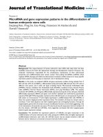
Figure 1a is a transmission electron microscopy (TEM)
image showing the NW tip. Figure 1b and c are high-res-
olution TEM images showing a layer of silver oxide with
varying thickness on the NW surface. The ZnO NWs were
synthesised using the vapour–liquid–solid (VLS) method
with a wurtzite structure and growth direction of [0001]
[17]. Figure 1d is a SEM image showing the tip of a ZnO
NW, which appears to be flat.
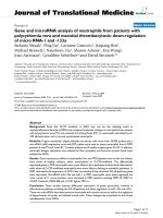
In situ SEM buckling tests of NWs were conducted as
shown in Fig. 2. A nanomanipulator (Klocke Nanotechnik,
Germany) that possesses 1 nm resolution in three orthog-
onal directions was used to pick up individual NWs
[18, 19]. A NW was clamped onto the tungsten tip on the
nanomanipulator using electron beam-induced deposition
(EBID) of carbon. Then the NW was approached to make
contact with an AFM cantilever (OBL-10, Veeco). Carbon
deposition was not used at the NW–cantilever interface.
Compressive force was applied to the NW by the nanom-
anipulator movement, which led to buckling of the NW. In
this case, the boundary condition was fixed-pinned. Con-
tinued loading further changed the postbuckling shape of
the NW until sliding occurred at the NW–cantilever
interface.
After buckling of the NW, there exist two forces at the
NW–substrate interface, a compressive (normal) force and
a frictional (lateral) force. The compressive force on the
NW can be easily measured from the deflection of the
AFM cantilever; however, it is not trivial to measure
the friction force. Below we describe a method to measure
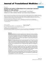
friction force based on the buckling theory. Free-body
diagram of a buckled member under fixed-pinned boundary
condition is shown in Fig. 3a, with the left end fixed and
the right end pinned. A small lateral deflection gives rise to
a moment M at the fixed end and shear force (friction force)
F at each end of the member. From the moment balance, it
can be easily obtained that F ¼ M=L, where L is the length
of the member. The governing equation at a section with a
distance x from the right end is given by
y
00
þ k
2
y ¼
M
EI
x
L
ð1Þ
where k
2
¼ P=EI, E is the Young’s modulus and I is the
moment of inertia. The solution to Eq. 1 is
y ¼ A sin kx þB cos kx þ
M
P
x
L
ð2Þ
Taking into account the fixed-pinned boundary
condition, we obtain
(c)
(b) (a)
oxide
oxide
(d)
Fig. 1 a–c TEM images of a silver NW; b, c show an oxide layer on
the surface of the silver NW; d SEM image of a ZnO NW
Fig. 2 Buckling process of an individual NW; a is before buckling
and b is after buckling and just prior to sliding on the right end
292 Nanoscale Res Lett (2010) 5:291–295
123
y ¼
M
P
x
L
þ 1:02 sin 4:49
x
L
hi
ð3Þ
Equation 3 describes the shape of the member in the
postbuckling stage. Details on the equation derivation can
be found elsewhere [20]. Eq. 3 provides the theoretical
basis of our method to measure the friction force. By fitting
the observed shape of the NW just prior to sliding to Eq. 3
using the nonlinear least squares method, M can be
determined since P is measured from the deflection of
the AFM cantilever. Then F can be obtained using F = M/L.
Figure 3b shows the fitting of a deformed NW to Eq. 3.
Clearly the agreement is very good.
Results and Discussion
Following the method described above, three silver NWs
and three ZnO NWs were tested for friction measure-
ments. The Amonton–Coulomb friction law is written as
F = lP, where l is the so-called coefficient of friction.
The normal force, friction force and coefficient of friction
for all six NWs are listed in Table 1. Note that these NWs
did not break in the buckling experiments so that each
NW was tested multiple times with very good repeat-
ability. However, the Amonton–Coulomb law was
obtained from empirical observations with many counte-
rexamples; for instance, geckos are able to move on walls
and ceilings when P B 0. A more fundamental friction
law that links friction and adhesion was proposed by
Bowden and Tabor [21],
F ¼ sA ð4Þ
where s is the interfacial shear strength and A is the true
contact area. This law has been supported by numerous
SFA and AFM experiments [10]. The two theories were
reconciled by considering the multiple asperities among the
contacting surfaces [22]; as a result the true contact area is
typically proportional to the normal force.
The NW–substrate contact is treated as the single-
asperity contact because the NW diameters are smaller than
the wavelength of the substrate topography. In order to
evaluate interfacial shear strength using Eq. 4, the true
contact area must be determined. In our experiments as
well as AFM experiments, the true contact area is calcu-
lated using continuum mechanics models. The well-known
Hertzian model does not take into account attractive
adhesion forces between the contacting surfaces. Other
widely accepted models that take adhesion force into
account are due to Johnson, Kendall, and Roberts (JKR)
[23], Derjaguin, Mutter, Toporov (DMT) [24] and Maugis
[25
], respectively.
For simplicity, the continuum models typically assume
the contact between a sphere and a flat surface. It is known
that the JKR and DMT theories are two extremes of a
spectrum of elastic solutions determined by the Tabor
parameter [26], which is given by
l ¼
16Rc
2
9K
2
z
3
0
1=3
ð5Þ
where R is the radius of the sphere, K is the reduced
modulus of two materials K ¼ 4=3½ð1 Àm
2
1
Þ=E
1
þð1 Àm
2
2
Þ
=E
2
À1
with E
1
and E
2
the respective Young’s moduli, and
m
1
and m
2
the respective Poisson’s ratios, z
0
is the inter-
atomic equilibrium distance (=0.2 nm), c is the interfacial
energy per unit area (work of adhesion). Each NW tip was
fitted with a sphere. When l [ 5, the JKR model is valid;
when l\0.1, the DMT model should be applied; in the
intermediate range, the Maugis model becomes appropri-
ate. In all our experiments 2.05 \ l \ 2.39 (see Table 2),
so the Maugis model should be used. However, the Maugis
model does not have an explicit expression for contact
L
F
P
M
F
P
x
y
(a)
)]
1443.4
49.4sin(02.1
1443.4
[5059.0
xx
y +=
(b)
Fig. 3 a Free-body diagram of a buckled column with fixed-pinned
boundary condition. Right end is the NW-substrate interface. b Non-
linear least squares fitting of Eq. 3 to digitized shape of a NW prior to
sliding
Table 1 Normal force, friction force and coefficient of friction in
each experiment
Sample Silver
1
Silver
2
Silver
3
ZnO
1
ZnO
2
ZnO
3
Normal force P
(nN)
263 277 465 186 203 215
Friction force F
(nN)
32.5 31.7 40.0 18.6 30.8 21.1
Coefficient of
friction l
0.12 0.11 0.09 0.10 0.15 0.10
Nanoscale Res Lett (2010) 5:291–295 293
123
radius. For the Tabor parameter in this range, the JKR
model was found to approximate the Maugis solution very
closely [27], therefore the JKR model was used in our
calculation due to its explicitness.
Following the Hertz and JKR models, the contact radius
a as a function of the externally applied load P is given by
a ¼
PR
K
!
1=3
ð6aÞ
a ¼
R
K
P þ3cpR þ
ffiffiffiffiffiffiffiffiffiffiffiffiffiffiffiffiffiffiffiffiffiffiffiffiffiffiffiffiffiffiffiffiffiffiffi
6cpRP þ 3cpRðÞ
2
q
!
1=3
ð6bÞ
respectively, where c ¼ c
1
þ c
2
À c
12
% 2
ffiffiffiffiffiffiffiffiffi
c
1
c
2
p
with c
1
and c
2
the respective surface energy and c
12
the interface
energy. c
1
= 1.37 J/m
2
for gold, c
2
= 0.8 J/m
2
for silver
oxide [28] and c
2
= 1.74 J/m
2
for ZnO with {0001} sur-
face [29]. Therefore, c = 2.09 J/m
2
and c = 3.09 J/m
2
for
the contacts between gold and silver oxide and between
gold and ZnO, respectively. In addition, E
gold
= 78 GPa,
E
silver
= 84 GPa, E
ZnO
= 140 GPa, m
gold
¼ 0:44, m
silver
¼
0:37, m
ZnO
¼ 0:30 [30]. The contact radius, contact pressure
and interfacial shear strength calculated using the two
models are listed in Table 2. It can be seen that the inter-
facial shear strengths between silver NW and gold
substrate and between ZnO NW and gold substrate are
134–139 MPa and 78.9–95.3 MPa, respectively, according
to the JKR model. These values are in good agreement with
those obtained from AFM and mesoscale friction tester in
similar environment (vacuum or dry) [31].
Several issues related to the experiments and data
analyses are discussed. First of all, our measurements
showed that no metallic bonding formed between silver
NWs and the gold substrate as the strength of metallic
bonding is typically on the order of GPa [32]. This is due to
the presence of a thin layer of silver oxide, as shown in the
high-resolution TEM images (Figure 1). Second, it is not
appropriate to treat the ZnO NWs as the molecular junc-
tions where the contact areas remain constant (in our case
the NW cross-sections) [33], otherwise the interfacial shear
strength would be too small. This is reasonable because it
is very likely that the NW is not perfectly perpendicular to
the substrate. Edge of the NW tip could be in contact with
the substrate, and the contact area can then be approxi-
mately fitted with a sphere. Third, previous experiments
showed that electron beam increases adhesion force
between semiconductors and metals [34, 35]. For contacts
between ZnO NW tips and a gold substrate, we found the
adhesion force did not show noticeable change when the
contact area was exposed to electron beam only for a short
time (e.g., less than 10 s) [36]. Last, although our experi-
mental method gave rise to the first measurement of the
friction data between NW tips and a substrate, we are
aware that it cannot measure the friction as a function of
the progressively applied normal force. MEMS devices
with simultaneous normal and lateral force measurement
capability are under development to address this issue.
Our results on interfacial friction and shear strength
could have direct implication on the AFM three-point
bending tests that are widely used in extracting mechanical
properties of one-dimensional nanostructures including
CNTs and NWs [37, 38]. Often the adhesion between the
NWs and the substrate is assumed to be strong enough to
provide a fixed–fixed boundary condition for the three-
point bending tests. The assumption is valid for NWs with
small diameters; but for those with large diameters, it could
lead to large data scatter as typically observed in experi-
ments. Our results could be incorporated into data reduc-
tion in the three-point bending experiments to quantify the
influence of adhesion and friction on the measured
mechanical properties. Other methods that could also be
used to eliminate the ambiguity caused by the NW–sub-
strate friction in the three-point bending tests include EBID
of platinum or carbon to reinforce the clamps [39].
Conclusions
In summary, a new experimental method to measure the
friction between a NW tip and a substrate has been
developed. Silver and ZnO NWs were tested with a gold-
coated surface as the substrate. The coefficients of friction
between silver NW and gold substrate and between ZnO
NW and gold substrate were found to range from 0.09 to
0.12 and from 0.10 to 0.15, respectively. The adhesion
between NWs and the substrate substantially modified the
Table 2 Contact pressure and interfacial shear strength using the
Hertz and JKR models
Sample Silver
1
Silver
2
Silver
3
ZnO 1 ZnO 2 ZnO 3
Tip radius R (nm) 27 27 29 25 40 25
Tabor’s parameter 2.28 2.28 2.33 2.05 2.39 2.05
Hertz model
Contact radius
a (nm)
4.79 4.87 5.93 3.90 4.69 4.09
Contact pressure
(GPa)
3.65 3.72 4.21 3.90 2.94 4.09
Shear stress s
(MPa)
451 425 362 390 445 402
JKR model
Contact radius a
(nm)
8.d 8.68 9.58 8.32 11.1 8.40
Contact pressure
(GPa)
1.21 1.17 1.61 0.86 0.52 0.97
Shear stress s
(MPa)
139 134 139 85.6 78.9 95.3
294 Nanoscale Res Lett (2010) 5:291–295
123
true contact area, which in turn affected the interfacial
shear strength significantly. According to the calculated
Tabor parameter, the JKR model was selected to approxi-
mately calculate the contact area and the interfacial shear
strength. The interfacial shear strengths between silver NW
and gold substrate and between ZnO NW and gold sub-
strate ranged from 134 to 139 MPa and from 78.9 to
95.3 MPa, respectively. These values are in good agree-
ment with previous results obtained in similar environment
(vacuum or dry) [31].
Acknowledgement This work was supported by the National Sci-
ence Foundation under Award No. CMMI-0826341 and the Faculty
Research and Professional Development Fund from North Carolina
State University. We thank to Fengru Fan and Afsoon Soudi for
kindly providing the NW samples.
References
1. W. Lu, C.M. Lieber, Semiconductor nanowires. J. Phys. D Appl.
Phys. 39(21), R387–R406 (2006)
2. F. Patolsky, C.M. Lieber, Nanowires nanosensors. Mater. Today
8, 20–28 (2005)
3. Z.L. Wang, J.H. Song, Piezoelectric nanogenerators based on
zinc oxide nanowire arrays. Science 312(5771), 242–246 (2006)
4. M. Law, L.E. Greene, J.C. Johnson, R. Saykally, P.D. Yang,
Nanowire dye-sensitized solar cells. Nat Mater 4(6), 455–459
(2005)
5. H.J. Dai, J.H. Hafner, A.G. Rinzler, D.T. Colbert, R.E. Smalley,
Nanotubes as nanoprobes in scanning probe microscopy. Nature
384(6605), 147–150 (1996)
6. L. Ge, S. Sethi, L. Ci, P.M. Ajayan, A. Dhinojwala, Carbon
nanotube-based synthetic gecko tapes. Proc. Natl Acad. Sci. USA
104(26), 10792–10795 (2007)
7. Z.L. Wang, Towards self-powered nanosystems: from nanogen-
erators to nanopiezotronics. Adv. Funct. Mater. 18(22), 3553–
3567 (2008)
8. M.R. Falvo, R. Superfine, Mechanics and friction at the nano-
meter scale. J. Nanopart. Res. 2, 237–248 (2000)
9. A.D. Corwin, M.P. de Boer, Effect of adhesion on dynamic and
static friction in surface micromachining. Appl. Phys. Lett.
84(13), 2451–2453 (2004)
10. R.W. Carpick, M. Salmeron, Scratching the surface: Fundamental
investigations of tribology with atomic force microscopy. Chem.
Rev. 97(4), 1163–1194 (1997)
11. G. Conache, S.M. Gray, A. Ribayrol, L.E. Froberg, L. Samuel-
son, H. Pettersson, L. Montelius, Friction measurements of InAs
nanowires on silicon nitride by AFM manipulation. Small 5(2),
203–207 (2009)
12. J.D. Whittaker, E.D. Minot, D.M. Tanenbaum, P.L. McEuen,
R.C. Davis, Measurement of the adhesion force between carbon
nanotubes and a silicon dioxide substrate. Nano Lett. 6(5), 953–
957 (2006)
13. M.P. Manoharan, M.A. Haque, Role of adhesion in shear strength
of nanowire-substrate interfaces. J. Phys. D Appl. Phys. 42(9),
095304 (2009)
14. Y.G. Sun, B. Mayers, T. Herricks, Y.N. Xia, Polyol synthesis of
uniform silver nanowires: a plausible growth mechanism and the
supporting evidence. Nano Lett. 3(7), 955–960 (2003)
15. Z.L. Wang, Zinc oxide nanostructures: growth, properties and
applications. J. Phys. Condens. Matter 16(25), R829–R858 (2004)
16. F. R. Fan, Y. Ding, D.Y. Liu, Z.Q. Tian, Z. L. Wang, Facet-
selective epitaxial growth of heterogeneous nanostructures of
semiconductor and metal: ZnO nanorods on Ag nanocrystals.
J. Am. Chem. Soc. 131(34), 12036–12037 (2009)
17. A. Soudi, E.H. Khan, J.T. Dickinson, Y. Gu, Observation of
unintentionally incorporated nitrogen-related complexes in ZnO
and GaN nanowires. Nano Lett. 9(5), 1844–1849 (2009)
18. Y. Zhu, H.D. Espinosa, An electromechanical material testing
system for in situ electron microscopy and applications. Proc.
Natl Acad. Sci. USA 102(41), 14503–14508 (2005)
19. Y. Zhu, F. Xu, Q.Q. Qin, W.Y. Fung, W. Lu, Mechanical prop-
erties of vapor-liquid-solid synthesized silicon nanowires. Nano
Lett. ASAP 9(11), 3934–3939 (2009)
20. A. Chajes, Principles of Structural Stability Theory (Prentice-
Hall, Englewood Cliffs, NJ, 1974)
21. F.P. Bowden, D. Tabor, The Friction and Lubrication of Solids
(Oxford University Press, Oxford, UK, 1954)
22. J.A. Greenwood, J.B.P. Williams, Contact of nominally flat sur-
faces. Proc. R. Soc. Lond. A Math. Phys. Sci. 295(1442), 300 (1966)
23. K.L. Johnson, K. Kendall, A.D. Roberts, Surface energy and
contact of elastic solids. Proc. R. Soc. Lond. A Math. Phys. Sci.
324(1558), 301 (1971)
24. B.V. Derjaguin, V.M. Muller, Y.P. Toporov, Effect of contact
deformations on adhesion of particles. J. Colloid Interface Sci.
53(2), 314–326 (1975)
25. D. Maugis, Adhesion of spheres—the JKR-DMT transition using
a Dugdale model. J. Colloid Interface Sci. 150(1), 243–269
(1992)
26. D. Tabor, Surface forces and surface interactions. J. Colloid
Interface Sci. 58(1), 2–13 (1977)
27. R.W. Carpick, D.F. Ogletree, M. Salmeron, A general equation
for fitting contact area and friction vs load measurements.
J. Colloid Interface Sci. 211(2), 395–400 (1999)
28. J.N. Israelachvili, Intermolecular and Surface Forces, 2nd edn.
(Academic Press, Amsterdam, 1991)
29. M. Kim, Y.J. Hong, J. Yoo, G.C. Yi, G.S. Park, K.J. Kong,
H. Chang, Surface morphology and growth mechanism of cata-
lyst-free ZnO and Mg
x
Zn
1-x
O nanorods. Phys. Status Solidi-
Rapid Res. Lett. 2(5), 197–199 (2008)
30. M. Lucas, W. Mai, R. Yang, Z.L. Wang, E. Riedo, Aspect ratio
dependence of the elastic properties of ZnO nanobelts. Nano Lett.
7(5), 1314–1317 (2007)
31. D.W. Xu, K. Ravi-Chandar, K.A. Liechti, On scale dependence in
friction: transition from intimate to monolayer-lubricated contact.
J. Colloid Interface Sci. 318(2), 507–519 (2008)
32. B. Bhushan, Nanotribology and Nanomechanics: An Introduction
(Heidelberg, Springer, 2008)
33. Q.Y. Li, K.S. Kim, Micromechanics of friction: effects of
nanometre-scale roughness. Proc. R. Soc. Lond. A Math. Phys.
Sci. 464(2093), 1319–1343 (2008)
34. H.T. Miyazaki, Y. Tomizawa, S. Saito, T. Sato, N. Shinya,
Adhesion of micrometer-sized polymer particles under a scanning
electron microscope. J. Appl. Phys. 88(6), 3330–3340 (2000)
35. W.Q. Ding, Micro/nano-particle manipulation and adhesion
studies. J. Adhesion Sci. Technol. 22(5–6), 457–480 (2008)
36. Q.Q. Qin, F. Xu, Y. Zhu, Adhesion between zinc oxide nanowires
and gold coated surfaces. J. Appl. Phys. (2009) (submitted)
37. J.P. Salvetat, G.A.D. Briggs, J.M. Bonard, R.R. Bacsa, A.J. Kulik,
T. Stockli, N.A. Burnham, L. Forro, Elastic and shear moduli of
single-walled carbon nanotube ropes. Phys. Rev. Lett. 82(5), 944–
947 (1999)
38. H. Ni, X.D. Li, H.S. Gao, Elastic modulus of amorphous SiO
2
nanowires. Appl. Phys. Lett. 88, 043108 (2006)
39. Y. Zhu, C. Ke, H.D. Espinosa, Experimental techniques for the
mechanical characterization of one-dimensional nanostructures.
Exp. Mech. 47(1), 7–24 (2007)
Nanoscale Res Lett (2010) 5:291–295 295
123