Báo cáo hóa học: " The Nature of Surface Oxides on Corrosion-Resistant Nickel Alloy Covered by Alkaline Water docx
Bạn đang xem bản rút gọn của tài liệu. Xem và tải ngay bản đầy đủ của tài liệu tại đây (550.46 KB, 7 trang )
NANO EXPRESS
The Nature of Surface Oxides on Corrosion-Resistant Nickel Alloy
Covered by Alkaline Water
Jiaying Cai
•
D. F. Gervasio
Received: 16 November 2009 / Accepted: 17 December 2009 / Published online: 5 January 2010
Ó The Author(s) 2010. This article is published with open access at Springerlink.com
Abstract A nickel alloy with high chrome and molyb-
denum content was found to form a highly resistive and
passive oxide layer. The donor density and mobility of ions
in the oxide layer has been determined as a function of the
electrical potential when alkaline water layers are on the
alloy surface in order to account for the relative inertness of
the nickel alloy in corrosive environments.
Keywords EIS Á Mott–Schottky Á Bipolar plates Á
High-temperature PEM fuel cell Á Nickel alloy
Introduction
Nickel metal alloys are corrosion resistant and can serve
as structural materials in extraordinary environments, e.g.,
in long-term storage containers, high-temperature heat
exchangers and aggressive chemical reactors. The stability
is often attributed to the inertness of the oxides that form on
the nickel alloys. One new application of these extraordi-
nary alloys is as the structural material for a metal bipolar
plate in a polymer electrolyte membrane (PEM) fuel cell
stack.
The bipolar plate is among the most expensive, heaviest
and voluminous components in the fuel cell stack. The
bipolar plates conduct current between cells, provide flow
channels for reactants and products, facilitate water and
thermal management and constitute the structural backbone
of a fuel cell stack. The materials for bipolar plates need to
have high electric and thermal conductivity, good corrosion
resistance and mechanical strength. Replacing bulky, brit-
tle machined graphite plates by thin, durable stamped metal
plates is particularly desirable for portable and mobile
applications where lower bulk, fragility and cost are all
needed.
After an earlier accelerated corrosion screening test [1],
the high chrome molybdenum nickel alloys, such as
Hastelloy C22 (composition given in Table 1), were con-
sidered one of the few materials with structural stability
that is suitable for use in bipolar plates for a high-tem-
perature PEM fuel cell stack.
Compared with graphite, C22 can be made into bipolar
plates from much thinner sheets. The thickness of a C22
metal sheet is\0.1 mm, whereas that of a graphite sheet is
[2–5 mm. The C22 can be formed into a bipolar plate by a
lower cost stamping as the manufacturing method, which
costs only 10 cents to $1 per plate when compared to $5–$25
per plate for the milling or molding a graphite plate [2].
These features of metal bipolar plates are desirable for
making a more compact, lighter weight and lower cost fuel
cell stack.
Most importantly, alloy C22 shows remarkable corro-
sion resistance and stability that is suitable in the aggres-
sive fuel cell environment. A number of studies on its
general and local corrosion resistance suggest that C22 has
excellent resistivity in a broad range of concentrated brines
including chloride, fluoride, carbonate, sodium and calcium
over a large pH and temperature range [3]. It is mainly due
to the formation of a protective passive oxide layer on the
surface. This occurs through electrochemical ‘‘local cell’’
on the metal surface, where oxygen reduction occurs at
one localized metal surface site by accepting electrons
J. Cai (&)
Department of Chemical Engineering, Arizona State University,
Tempe, AZ, USA
e-mail:
D. F. Gervasio
Department of Chemical Engineering, University of Arizona,
Tucson, AZ, USA
123
Nanoscale Res Lett (2010) 5:613–619
DOI 10.1007/s11671-009-9521-5
generated during metal oxidation occurring at another
localized site through electron conduction in the bulk metal
[4]. The oxygen reduction site becomes alkaline, and metal
oxidation site becomes acidic. Nickel alloy was placed in
aqueous potassium hydroxide solution and exposed to
various oxidizing potentials representative of a bipolar
plate at an oxygen cathode. Electrochemical impedance
spectroscopic (EIS) and Mott–Schottky (M–S) methods
were used to determine the density and mobility of charge
carriers in the passive oxide layer to understand the nature
of the surface oxides and how these affect the corrosion
resistance of C22 nickel alloy covered by alkaline water.
Experimental
Electrochemical Measurements
All electrochemical experiments were carried out using a
three-electrode configuration at room temperature. The
working electrode was nickel alloy C22 (Haynes),
machined into 6 cm 9 2cm9 0.2 cm. The working
electrode was abraded with 1200-grit SiC paper, polished
with 1.0, 0.3 and 0.05 lmAl
2
O
3
powder and then ultra-
sonically cleaned in deionized water. The working elec-
trode area was 12 cm
2
. A Ag/Ag
2
O reference electrode was
used in 0.1 M KOH (pH 13.0) and in 1.0 M KOH (pH
13.8) electrolyte solution. The potential of the silver/silver-
oxide reference electrode is 0.321 V versus RHE in 0.1 M
KOH and 0.341 V versus RHE in 1.0 M KOH. This can
be related to NHE (pH = 0) by the potential shift with
pH using the Nernst equation. A graphite rod was used
as the counter electrode. The aqueous alkaline potassium
hydroxide solutions of two concentrations (0.1 M, pH 13.0
and 1.0 M, pH 13.8) were prepared using pure deionized
water (PureLab Ultra system) and potassium hydroxide
stock (analytical-grade reagent). The solution was deaer-
ated with ultrapure nitrogen gas for 30 min prior to starting
the experiment, and this nitrogen purge was continued
throughout each experiment. Voltammetry of Alloy C22
was performed to determine the electrochemical processes
that occur on the moisture-covered alloy surface. After
freshly abrading the C22 working electrode, it was
cathodically polarized at -1.3 V for at least 20 min to
remove the air-formed oxide film, then the potential was
swept from -1.3 to 0.5 V at a scan rate of 20 mV/s to
survey the surface processes. The C22-alloy working
electrode was held for 2 h at each film formation potential
to grow the passive oxide films.
EIS and M–S tests were carried out immediately after the
passive films were formed. For EIS measurements, the fre-
quency was analyzed over a range of 10 kHz–1 MHz with a
peak-to-peak modulation amplitude voltage of 20 mV. And
then, the M–S experiments were done by measuring the
frequency at 1 kHz during a negative potential scan from
?0.2 to -1.1 V in 50 mV-increments.
All electrochemical experiments were performed using a
Princeton Applied Research VMP2/Z Multichannel Poten-
tiostat (Oak Ridge, TN) running EC-Lab version 9.13 soft-
ware, and the impedance spectra analyses were performed
using Zsimpwin software.
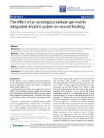
Interfacial Contact Resistance (ICR)
ICR should be minimized for bipolar plates to achieve high
efficiency in PEM fuel cells. ICR measurement was con-
ducted on the Hastelloy C22 after the electrochemical
oxidization. The apparatus for measuring ICR is illustrated
in Fig. 1, showing two pieces of carbon paper (SIGRACET,
type GDL 10 AA, a gas diffusion layer used in PEM fuel
cells) sandwiched between the sample and two copper
plates. Compaction force was applied by a hydraulic press.
The potential difference V across the cell and the copper
plates was measured by an ohmmeter while a fixed elec-
trical current I (0.9 A) was passed through the arrangement.
The ICR was calculated as follows [5]:
ICR ¼
R ÀRcp
2
 A
Copper plate
Copper plate
V
0.9 A
Sample
Carbon paper
Carbon paper
Fig. 1 Apparatus used to measure interfacial contact resistance
Table 1 Chemical composition (wt%) of Alloy C22
Co Cr Fe Mn Mo Ni P S Si V W
C22 1.45 15.74 5.58 0.50 15.53 57.55 0.008 0.003 0.02 0.163 3.54
614 Nanoscale Res Lett (2010) 5:613–619
123
where R is the total resistance (V/I), Rcp represents the
resistant contribution due to the carbon paper/copper plates
(*5mX) and A is the sample area (cm
2
). The value of ICR
was greatly affected by the compaction force, and good
reproducibility could be obtained only with compaction
force above 200 N cm
-2
[5, 6].
Auger Electron Spectroscopy (AES)
In order to determine the general composition of surface-
oxidized C22, AES was performed to get depth profile for
oxidized samples. AES analyses were carried out on speci-
mens at sputter rate of 2.0 nm per minute with beam current
of 1.0 lA and beam voltage of 4.0 kV using Physical
Electronics 590 Scanning Auger Microprobe.
Results and Discussion
Cyclic Voltammetry
The cyclic voltammogram presented in Fig. 2 shows the
surface processes occurring on alloy C22 in both 0.1 M
(pH 13.0) and 1.0 M KOH (pH 13.8) solution. Figure 2a
shows that the first cycle was noticeably different than the
successive cycles. The first positive-going sweep shows
extra anodic current from -0.7 to 0.3 V, suggesting the
formation of a metal oxide layer on the alloy C22 surface.
The reverse scan showed the reduction peak between 0.1
and 0.3 V in the first and succeeding negative-going scans.
The second and successive positive- and negative-going
scans showed growing oxidation and reduction peaks.
After the third cycle, the growth rate of both oxidation
and reduction peaks decreased and were virtually sta-
ble. Figure 2b shows a similar behavior for the cyclic
voltammogram of the C22 in 1.0 M KOH, except there are
two noticeable differences. First, there is a slight shift for
the anodic peak, which was 0.3 V (vs. Ag/Ag
2
O/0.1 M
KOH) for 0.1 M KOH and 0.26 V (vs. Ag/Ag
2
O/1.0 M
KOH) for 1.0 M KOH solutions. Secondly, both the oxi-
dation and reduction peak currents were about two times
larger in the solution with 1 M versus 0.1 M KOH.
Interfacial Contact Resistance (ICR)
Figure 3 shows the comparison of the ICR of the alloy oxi-
dized at different potentials in both 1.0 M KOH (pH 13.8)
and 0.1 M KOH (pH 13.0) solutions. The results showed that
the alloy oxidized in 0.1 M KOH had a higher ICR value than
that in 1.0 M KOH solution. In both solutions, the ICR values
were higher in the passive region (-0.5 to -0.1 V) and
decreased at the higher potential conditions.
Generally, the influence of Cr-oxide on the Ni-based
material resistance is very complex, and it can be considered
-10
-5
0
5
10
15
-1.5 -1 -0.5 0 0.5
E (volt) vs Ag/Ag
2
I (milliAmp)
1st scan
2 nd scan
3rd scan
-10
-5
0
5
10
15
-1.5 -1 -0.5 0 0.5
E (volt) vs Ag/Ag
2
O in 1M KOH
I (milliAmp)
1st scan
2nd scan
3 rd scan
O in 0.1M KOH
(a) (b)
Fig. 2 a, b CV of C22 in 0.1 M and 1.0 M KOH
32
34
36
38
40
42
1234
E (volt)
R
contact
(milliohm cm
2
)
1.0 M KOH 0.1 M KOH
Fig. 3 Interfacial contact resistance of alloy C22 after oxidized at -
0.5, -0.1, 0.1 and 0.2 V in 1.0 and 0.1-M KOH solutions
Nanoscale Res Lett (2010) 5:613–619 615
123
that the decrease of conductivity follows the trend that the
conductivity of Ni-oxide is greater than the conductivity of
Cr-oxide [5]. Therefore, it appears that when alloy C22 is
oxidized in 0.1 M KOH solution, a larger amount of Cr-
oxide forms on the surface, which results in a higher value of
ICR. The depth profile for the oxide films on C22 by AES
(not shown here) showed more Cr-oxide was formed in
0.1 M KOH, which is consistent with this assertion.
Impedance Measurement
EIS and M–S tests were carried out on the passive films
formed at different potentials in order to investigate the
influence of the film formation potential on the character of
passive films on alloy C22. The Nyquist plots are shown in
Fig. 4a and c for the nickel alloy in 1.0 and 0.1 M KOH
electrolyte. The impedance data can be modeled by a
simple equivalent circuit Rs (CscRp), where Rs is the
electrolyte solution resistance, Csc is the space charge
capacity and Rp is the polarization resistance. It is clear
that the impedance response is sensitive to the film for-
mation potential. In both 0.1- and 1-M KOH solutions,
smaller arcs were observed in the potential range of 0.2 and
0.4 V, while larger ascending arcs, which do not form
semicircles on the real axis, are observed between -0.3
and -0.1 V. This phenomenon is more clearly shown in
Fig. 4b and d, where Rp initially increased with potentials
(within the passive range), but when potentials are within
the trans-passive region (E [ -0.1 V), Rp decreases with
E. The existence of the resistance Rp versus E peak can be
attributed to the establishment of passive oxide layer in the
beginning and then the oxidative ejection of chromium
cations from the barrier oxide layer [7].
The impedance behavior for alloy C22 in the 0.1- and
1-M KOH solutions show one systematic difference,
namely, the arcs are always larger in 0.1 M KOH. It
appears that the higher concentration of [OH]
-
ions results
in a less-resistive passive oxide film on the nickel alloy
surface, especially in the potential range between -0.5 and
-0.1 V. The possible formation process of metal oxide is
presented as follows.
M ! M
xþ
þ e
xÀ
½OH
À
þ M
xþ
! M½OH
x
! MO
x=2
Having more [OH]
-
ions in solution favors the above
reaction, and hence, the quick formation of an passive
oxide layer, which covers the metal surface and slowed
down the further oxidization of metal.
Following each EIS measurement, an M–S test was
performed to study the semiconducting properties of a
passive oxide film that was formed on the surface of the
nickel alloy. The M–S analysis measures the electrode
capacitance as a function of potential. Under depletion
conditions, the M–S relationship is given by Eq. (1)
0
5000
10000
15000
20000
25000
0
10000
20000
30000
40000
50000
-Im [Z] / ohm
Re [Z] / ohm
E / V (vs Ag/Ag
2
O/1.0M KOH)
in 1.0 M KOH
0
10
20
30
40
50
60
Potential (V)
Interficial Resistance (*e3 ohm)
0
50000
100000
150000
0
20000
40000
60000
80000
100000
-Im [Z] / ohm
Re [Z] / ohm
E / V (vs Ag/Ag
2
O/0.1M KOH)
in 0.1M KOH (pH 13.0)
0
50
100
150
200
250
300
350
-0.6 -0.4 -0.2 0.0 0.2 0.4
-0.6 -0.4 -0.2 0 0.2 0.4
-0.6 -0.4 -0.2 0.0 0.2 0.4
-0.6 -0.4 -0.2 0 0.2 0.4
E (V)
Interficial Resistance (*e3 ohm)
(a) (b)
(c)
(d)
Fig. 4 a, b EIS of C22 in 1.0 M KOH. c, d EIS of C22 in 0.1 M KOH
616 Nanoscale Res Lett (2010) 5:613–619
123
1
C
2
SC
¼
2
eee
0
NA
2
V
E
À V
fb
À
kT
e
ð1Þ
where C
SC
is the space charge capacitance, e is the dielectric
constant of the semiconductor, e
0
is permittivity of free
space (8.854e
-14
F/cm), N is defect density (electron donor
concentration for n-type semiconductor or hole acceptor
concentration for p-type semiconductor) and k is the
Boltzmann constant. kT/e is the thermal voltage, which is the
voltage a single charge falls through to pick up the thermal
energy. kT/e is about 25 mV at the ambient temperature.
The M–S analysis assumes the space charge capacitance
is much smaller than the double-layer capacitance such that
the contribution of double-layer capacitance to the total
capacitance value could be negligible. For a p-type semi-
conductor, C
À2
SC
versus E should be linear with a negative
slope, which is inversely proportional to the acceptor
density N. For an n-type semiconductor, the slope should
be positive.
Figure 5 shows the M–S plots recorded at 1 kHz fre-
quency for passive films formed on Alloy C22 in 1.0- and
0.1-M KOH solutions at different potentials.
As shown in Fig. 5b, the capacitance decreased (C
À2
SC
increased) at low potentials (-1.1 \ E \ -0.8 V), sug-
gesting an n-type semiconductor. At higher potentials
(E [ -0.1 V), however, the capacitance increased (C
À2
SC
decreased), showing a p-type semiconductor. The change
of the electronic character is more likely due to the gen-
eration of the cation vacancies at film/solution interface
through the oxidative ejection of cations from the film [8].
This result is consistent with the above Nyquist plots where
the most resistant film was formed at the potential of
-0.1 V, where the change of electronic character appeared.
Over the potential range between -0.8 and -0.1 V, the
capacitance was nearly constant, for those passive films
formed at lower potentials (-0.5, -0.3, -0.2, -0.1 and
0.1 V). This phenomenon was also reported by Da Belo
et al. [9] on Ni-20% Cr alloy in pH 9.2 borate buffer. For
those passive films formed at higher potentials (0.2, 0.26
and 0.34 V), there was no clear potential range over which
the capacitance varies slightly. Their M–S profiles behaved
similar to those of the films on pure Cr, which presents a
peak in the C
À2
SC
versus E plots followed by a steadily linear
region negative slope (see [10]).
Defect density N of the passive films could also be
determined by the slope of the linear part of M–S profile.
Both the donor density calculated from the n-type part and
the acceptor density from the p-type part in passive films
formed in 1.0-M KOH electrolyte solution are larger than
those formed in 0.1-M KOH solution (see Fig. 6). The
0.0E+00
5.0E-05
1.0E-04
-1.2 -0.8 -0.4 0 0.4
E (volt) vs Ag/Ag
2
O in 0.1 M KOH
C
-2
(F
-2
)
-0.5 V
-0.1 V
0.3 V
0.35 V
0.E+00
5.E-05
1.E-04
-1.5 -1 -0.5 0 0.5
E (volt) vs Ag/Ag
2
O in 1 M KOH
C
-2
(F
-2
)
-0.5 V
-0.2 V
0.26 V
0.34 V
(b)
(a)
Fig. 5 a, b M–S test of C22 in
1.0 and 0.1 M KOH
n type
0
5
10
15
20
25
-0.6 -0.4 -0.2 0 0.2 0.4
Potential (volt) vs Ag/Ag
2
O
N
donor
( cm
-3
) x exp
20
1.0 M KOH 0.1M KOH
p type
0
5
10
15
20
25
-0.6 -0.4 -0.2 0 0.2 0.4
Potential (volt) vs Ag/ Ag
2
O
N
acceptor
( cm
-3
) xexp
20
1.0 M KOH 0.1 M KOH
(a)
(b)
Fig. 6 a, b Donor density
(acceptor density) versus film
formation potentials
Nanoscale Res Lett (2010) 5:613–619 617
123
higher defects concentration within the film resulted in
lower resistant passive films, and accordingly, higher
conductivity, which was in a good agreement with the ICR
and Nyquist results.
AES Depth Profile
Figure 7 showed the content of three major components
within the surface oxide films on alloy C22 versus the
depth of the films.
In all cases, the amount of Cr-oxide was slightly higher
in 0.1-M KOH than that in 1.0-M KOH solution. This
result is consistent with the effect of solution pH on the
ICR value, which was higher for the oxide films formed in
0.1 M KOH.
The depth profile (b) behaved quite different from the
other two cases. For the oxide film formed at -0.1 V, the
content of Cr-oxide is higher in the outer layer of the film,
which was *51% formed in 1.0 M KOH and *55% in
0.1 M KOH compared with *20% in the bulk alloy. It
decreased greatly from the outer to inner surface at the
depth of 2 nm, while the content of Ni-oxide increased and
finally dominated in the inner layer of the film. However,
for the oxide films formed at -0.5 and 0.26 V, this dual-
layered structure was not observed. And the Ni-oxides
were dominant through the entire oxide film. This result
could also be explained the highest value of ICR for the
oxide film formed at -0.1 V, which the higher amount of
Cr-oxide was responsible for the higher contact resistance.
The thickness of the oxide films was estimated by the depth
profile at the range of 3–4 nm, where the three components
Cr, Ni and Mo converged to a state value, respectively.
Conclusions
The oxide film that forms on nickel alloy C22 is affected by
film formation potential and pH. ICR and EIS show the
interfacial film resistance Rp is sensitive to the film for-
mation potential. The current for the formation of oxide
peaks at the potential of -0.1 V. More concentrated KOH
electrolyte solution contributes to the formation of less
resistant and hence larger peak current for this passive film
formation at 0.1 V on nickel alloy C22. The M–S analysis
of the oxide layer on nickel alloy C22 shows that the oxide
film on the nickel alloy is semiconducting when formed in
both 0.1- and 1-M KOH solutions. Over lower potential
range, the oxide film on nickel alloy C22 displays n-type
character, while p-type character is found at higher
potentials. Defect concentration obtained from the M–S
plots is higher when the film is formed in 1.0-M KOH
solution at all the investigated film formation potentials,
which is consistent with a lower film resistance for oxides
formed in 1-M compared to 0.1-M KOH solution. The AES
depth profile shows a dual-layered structure in the oxide
film formed at -0.1 V, where a Cr-rich outer layer is
responsible for the higher contact resistance. The amount
0
10
20
30
40
50
60
02468
depth (nm)
wt %
Cr_0.1 M KOH Ni_0.1 M KOH Mo_0.1M KOH
Cr_1.0 M KOH Ni_1.0 M KOH Mo_1.0 M KOH
(a)
0
10
20
30
40
50
60
02468
depth (nm)
% wt
Cr_0.1M KOH Ni_0.1M KOH Mo_0.1M KOH
Cr_1.0 M KOH Ni_1.0 M KOH Mo_1.0M KOH
(b)
0
10
20
30
40
50
60
02468
depth (nm)
% wt
Cr_0.1M kOH Ni_0.1 MKOH Mo_0.1MKOH
Cr_1.0 M KOH Ni_1.0 M KOH Mo_1.0 M KOH
(c)
Fig. 7 AES depth profile of the oxide film on alloy C22 formed at
-0.5 V (a), -0.1 V (b) and 0.26 V (c) in 0.1 and 1.0 M KOH
618 Nanoscale Res Lett (2010) 5:613–619
123
of Cr showed in the depth profile was higher in 0.1-M KOH
than that in 1.0-M KOH solution, which further confirmed
that a more resistive oxide film grows on the nickel alloy
when it is covered by a less concentrated aqueous KOH
(less basic) solution.
As is, this alloy is stable enough to be used as a bipolar
plate in a high-temperature polymer electrolyte membrane
fuel cell (HT PEM FC), but the surface conductance of this
alloy is too low to be used as a bipolar. However, coating
with a thin stable conductive layer, such as gold, will give
suitable surface conductivity. Because the Hastelloy C22 is
inert to corrosion, defect in the gold coating will not grow,
and a gold-coated Hastelloy C22 bipolar plate should be
suitable for use in a HT PEM fuel cell. Ongoing work
concerns testing this assertion in HT PEM fuel cell stacks.
Open Access This article is distributed under the terms of the
Creative Commons Attribution Noncommercial License which per-
mits any noncommercial use, distribution, and reproduction in any
medium, provided the original author(s) and source are credited.
References
1. D. Gervasio, J. Kinder, N. Hoskins, V. Onyeabor, S. Taghavi,
A.V. Pattekar, K. Fleckner, High temperature polymer electrolyte
membrane fuel cells (HT-PEMFCs) for portable power, Paper
number 2006-01-3096, Power Systems Conference, Fuel Cells
(Session Code: PSC6), Organizers—Michael Allen, Naval Air
Systems Command; Nathan Kumbar, NAVAIR, New Orleans
(2006)
2. K. Jayakumer, S. Pandiyan, N. Rajakshmi, K.S. Dhathathreyan,
Cost-benefit analysis of commercial bipolar plates for PEMFC’s.
J. Power Sources 161, 454–459 (2006)
3. J.J. Gray, C.A. Orme, Electrochemical impedance spectroscopy
study of the passive films of alloy 22 in low pH nitrate and
chloride environments. Electrochim. Acta 52, 2370–2375 (2007)
4. S.P. Rogers, D.F. Gervasio, Oxygen electro-reduction on C22 and
C276 nickel metal alloy. Electrochem. Soc. Trans. 3, 431–442
(2006)
5. R.F. Silva, D. Franchi, A. Leone, L. Pilloni, A. Masci, A. Pozio,
Surface conductivity and stability of metallic bipolar plate
materials for polymer electrolyte fuel cells. Electrochim. Acta 51,
3592–3598 (2006)
6. A. Pozi, F. Zaza, A. Masci, R.F. Silva, Bipolar plate materials for
PEMFCs: a conductivity and stability study. J. Power Sources
179, 631–639 (2008)
7. N. Priyantha, P. Jayaweera, D.D. MacDonald, A. Sun, An elec-
trochemical impedance study of Alloy 22 in NaCl brine at ele-
vated temperature. I. Corrosion behavior. J. Electroanal. Chem.
572, 409–419 (2004)
8. D.D. Macdonald, A. Sun, N. Priyantha, P. Jayaweera, An elec-
trochemical impedance study of Alloy-22 in NaCl brine at ele-
vated temperature: II. Reaction mechanism analysis. J.
Electrochem. Chem. 572, 421–431 (2004)
9. M. Da Belo, N.E. Hakiki, M.G.S. Ferreira, Semiconducting
properties of passive films formed on nickel–base alloys type
Alloy 600: influence of the alloying elements. Electrochim. Acta
44, 2473–2481 (1999)
10. M. Bojinov, G. Fabricius, P. Kinnunen, T. Laitinen, K. Ma
¨
kela
¨
,
T. Saario, G. Sundholm, Electrochemical study of the passive
behaviour of Ni-Cr alloys in a borate solution-a mixed-conduc-
tion model approach. J. Electroanal. Chem. 504, 29–44 (2001)
Nanoscale Res Lett (2010) 5:613–619 619
123