Báo cáo hóa học: " Research Article Channel Asymmetry in Cellular OFDMA-TDD Networks" docx
Bạn đang xem bản rút gọn của tài liệu. Xem và tải ngay bản đầy đủ của tài liệu tại đây (963.97 KB, 14 trang )
Hindawi Publishing Corporation
EURASIP Journal on Wireless Communications and Networking
Volume 2008, Article ID 121546, 14 pages
doi:10.1155/2008/121546
Research Article
Channel Asymmetry in Cellular OFDMA-TDD Networks
Ellina Foutekova,
1
Patrick Agyapong,
2, 3
and Harald Haas
1
1
Institute for Digital Communications, School of Engineering & Electronics, The University of Edinburgh, Edinburgh, EH9 3JL, UK
2
School of Engineering and Science, Jacobs University Bremen, 28759 Bremen, Germany
3
Department of Engineering and Public Policy, College of Engineering, Carnegie Mellon University, Pittsburgh, PA 15213, USA
Correspondence should be addressed to Ellina Foutekova,
Received 17 January 2008; Revised 22 July 2008; Accepted 28 October 2008
Recommended by David Gesbert
This paper studies time division duplex- (TDD-) specific interference issues in orthogonal frequency division multiple access-
(OFDMA-) TDD cellular networks arising from various uplink (UL)/downlink (DL) traffic asymmetries, considering both line-
of-sight (LOS) and non-LOS (NLOS) conditions among base stations (BSs). The study explores aspects both of channel allocation
and user scheduling. In particular, a comparison is drawn between the fixed slot allocation (FSA) technique and a dynamic channel
allocation (DCA) technique for different UL/DL loads. For the latter, random time slot opposing (RTSO) is assumed due to
its simplicity and its low signaling overhead. Both channel allocation techniques do not obviate the need for user scheduling
algorithms, therefore, a greedy and a fair scheduling approach are applied to both the RTSO and the FSA. The systems are
evaluated based on spectral efficiency, subcarrier utilization, and user outage. The results show that RTSO networks with DL-
favored traffic asymmetries outperform FSA networks for all considered metrics and are robust to LOS between BSs. In addition,
it is demonstrated that the greedy scheduling algorithm only offers a marginal increase in spectral efficiency as compared to the
fair scheduling algorithm, while the latter exhibits up to
≈20% lower outage.
Copyright © 2008 Ellina Foutekova et al. This is an open access article distributed under the Creative Commons Attribution
License, which permits unrestricted use, distribution, and reproduction in any medium, provided the original work is properly
cited.
1. INTRODUCTION
In the recent years, orthogonal frequency division multi-
plexing (OFDM) has been a subject of considerable interest
for cellular systems of beyond third generation (3G). Wong
et al. [1] show promising results for OFDM as a multiuser
technique, focusing particularly on the gains in using
adaptive modulation. Results, presented by Keller and Hanzo
in [2], also highlight the solid benefits of employing adaptive
modulation in OFDM systems. Later, Yan et al. [3]propose
an adaptive subcarrier, bit, and power allocation algorithm
for a multiuser, multicell OFDM system, which shows
significant improvement in throughput when compared to
an equal power allocation algorithm. Limiting assumptions
include frequency reuse of four, no Doppler effect, no
own-cell interference. The gains in combining OFDM with
an adequate multiple access scheme have been thoroughly
described in [4], specifically emphasizing on the superiority
of frequency division multiple access (FDMA).
The combination of OFDMA with time division duplex
(TDD), which enables the support of asymmetric services,
is of special interest [5]. However, in a system where cell-
specific asymmetry demands are to be supported, TDD
suffers from additional interference as compared to fre-
quency divisionduplex (FDD), namely same-entity interfer-
ence (base station (BS)
→BS and mobile station (MS) →
MS). A possible solution to the same-entity interference
problem is fixed slot allocation (FSA). The principle of FSA
is that the uplink-downlink (UL-DL) time slot assignment
ratio is kept fixed and constant across the cells in a network
(and usually allocates half of the resources to UL and DL
each). FSA is convenient because, most importantly, same-
entity interference is completely avoided, and, in addition,
the scheme is simple-to-implement and there is no signaling
overhead. The major disadvantage, however, is the lack of
flexibility. In other words, one of the primary advantages
of TDD, namely, the support for cell-specific asymmetry
demands is not exploited.
An interference mitigation technique, which retains the
advantages of TDD is random time slot opposing (RTSO)
[6]. In RTSO, each cell independently sets the number of
UL and DL time slots based on the cell-specific traffic
2 EURASIP Journal on Wireless Communications and Networking
Time slot
Frame
Time
Δt
Δt
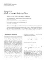
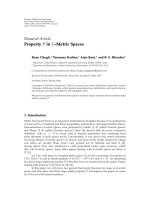
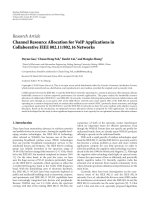
Figure 1: For a given ratio of UL/DL resources, RTSO only
permutes the UL and DL time slots once every time interval Δt
(greater than the frame duration) [6], keeping the UL/DL ratio
fixed. Upward-pointing arrow denotes UL, while DL is denoted by
a downward-pointing arrow.
asymmetry demand. In order to mitigate the same-entity
interference problem, the time slots are randomly permuted
within a frame once every time interval Δt (where Δt is
a network parameter) as illustrated in Figure 1.Theactual
time slot permutation sequence follows a pseudorandom
pattern. This pattern can be independently generated at
both ends (MS and BS). As a consequence, the signaling
effort is almost negligible since only a random code at link
setup needs to be conveyed. RTSO avoids persistent severe
interference, and in effect achieves interference diversity.
Note that an analogy can be made between RTSO and
frequency hopping. In the latter, interference diversity is
achieved by hopping through different frequency carriers.
RTSO has been previously applied to code division multiple
access (CDMA) systems [6].
The purpose of this paper is to explore interference
aspects arising from cell-specific traffic asymmetry demands
in OFDMA-TDD cellular networks, while jointly considering
channel allocation and user scheduling. A multiuser, mul-
ticell OFDMA-TDD network with full-frequency reuse is
studied, assuming both LOS and NLOS conditions among
the BSs. RTSO and FSA are the considered channel allocation
techniques and the two alternative scheduling algorithms are
the fair optimum target assignment with stepwise rate removals
(OTA-SRRs) [7] and the greedy rate packing (GRP) [8].
The rest of the paper is organized as follows. Section 2
presents the system model, while the employed scheduling
algorithms are described in Section 3. The simulation model
and results are given in Sections 4 and 5,respectively.
Concluding remarks are presented in Section 6.
2. SYSTEM MODEL
A wireless cellular network can be modeled mathemati-
cally by the signal-to-interference-plus-noise-ratio (SINR)
expression in the sense that the SINR expression holds infor-
mation about the model assumptions on interference sources
and power fading alike. In terms of power fading, the system
model considered in this study takes on a realistic cross-layer
approach to reflect both small-scale fading and large-scale
fading in a typical time-variant frequency-selective channel.
Small-scale fading pertains to the received signal power
variations with frequency, while large-scale fading pertains
to the received signal power variations with distance [9]. In
previous studies [1–4], one of these impairments is usually
neglected. However, for cellular OFDM systems with increas-
ing channel bandwidth (100 MHz for beyond 3G networks
[10]), it is important that both fading effects are considered
due to the frequency selectivity and frequency granularity,
introduced by OFDM. In terms of interference sources,
this study considers contributions from own-cell links and
other-cell links, termed multiple-access interference (MAI)
and cochannel interference (CCI), respectively. Furthermore,
impairments such as frequency offset errors due to Doppler
and lack of synchronization are also accounted for.
In what follows, expressions for the desired signal power
per subcarrier, the received MAI power, and the received CCI
power are presented, which are then combined to formulate
an SINR expression according to the system model described
above.
Let subcarrier k
∈ s ={a
1
, , a
m
},wherea
i
∈{1, ,
N
c
} and s is a set of subcarriers belonging to a single user in
cell i,andk does not experience interference from the set. The
cardinality of s,
|s|, is the number of subcarriers per user,
which can vary from zero to N
c
(total number of subcarriers
per BS). The received signal power on subcarrier k in cell i is
given by
R
i
k
= P
i
k
G
i
k
|H
i
k
|
2
[W], (1)
where P
i
k
is the transmit power on subcarrier k in cell i, G
i
k
is the path gain between the MS using subcarrier k and its
corresponding BS, and H
i
k
is the channel transfer function
for subcarrier k in cell i between the MS using subcarrier k
and its corresponding BS. Here, it should be noted that the
path loss reflects the variation of the received signal power
with distance, while the channel transfer function reflects the
variation of the received signal power with frequency.
The received MAI power on subcarrier k in UL is given
by (2), where it should be noted that MAI in DL is not
considered, as perfect synchronization is assumed due to the
synchronous nature of point-to-multipoint communication:
P
i
MAI,k
=
N
c
k
=1
k
/
∈s
P
i
k
G
i
k,k
|H
i
k,k
|
2
|C
i
k,k
(Δ f + ε
D
+ ω)|
2
[W],
(2)
where
C
i
k,k
(x) =
1
N
c
sin(πx)
sin(πx/N
c
)
exp
jπx(N
c
−1)
N
c
,(3)
G
i
k,k
is the path gain between the transmitter on the link
using subcarrier k
and the receiver on the link using
subcarrier k, H
i
k,k
is the transfer function of the channel
between the transmitter on the link using subcarrier k
and
Ellina Foutekova et al. 3
the receiver on the link using subcarrier k, C
i
k,k
(Δ f + ε
D
+
ω), given in (3), is a cyclic sinc function to account for
the amount of interference subcarrier k experiences from
subcarrier k
, j is the imaginary unit, Δ f = k
−k and ε
D
=
f
D,max
/δ
f
accounts for the Doppler shift (where f
D,max
is the
maximum Doppler frequency and δ
f
is the carrier spacing),
ω
= f
c
/δ
f
is the frequency offset due to synchronization
errors between subcarriers k and k
,andf
c
is the offset in
Hz. A derivation of the cyclic sinc function is presented in
Appendix C.
The received CCI power per subcarrier is modeled sim-
ilarly to the received MAI power and is given by (4), where
it should be noted that CCI contributions are expected not
only from the reused subcarrier but also from neighboring
subcarriers, when ε
D
and/or ω are non-zero:
P
i
CCI,k
=
B
l=1
l
/
=i
N
c
k
=1
P
l
k
G
l
k,k
|H
l
k,k
|
2
|C
l
k,k
(Δ f + ε
D
+ ω)|
2
[W],
(4)
where B is the number of cells under consideration (cells that
contribute nonnegligible interference).
The cyclic sinc function used in modeling MAI and
CCI controls the amount of interference subcarrier k
causes to subcarrier k. Given the same transmit power, link
gain, and channel, with an increase in
|k
− k + ε
D
+ ω|,
the interference contribution decreases. This behavior is
expected as synchronization errors and Doppler effects are
significant to neighboring subcarriers and become negligible
when the subcarriers are spaced relatively far apart.
Based on (1) through (4), the achieved SINR on subcar-
rier k
∈ s in cell i, γ
i
k
,canbewrittenas
γ
i
k
=
P
i
k
G
i
k
B
l=1
N
c
k
=1
if l
=i,k
/
∈s
P
l
k
G
l
k,k
(·)+n
,(5)
where
G
i
k
= G
i
k
|H
i
k
|
2
is the weighted gain on the “desired”
link for subcarrier k
∈ s,
G
l
k,k
(·) = G
l
k,k
|H
l
k,k
|
2
|C
l
k,k
(Δ f +
ε
D
+ ω)|
2
is the weighted gain of the interfering link between
the transmitter on the link using subcarrier k
and the
receiver on the link using subcarrier k,andn is the thermal
noise power per subcarrier. As MAI in DL is not considered,
in the case of DL SINR calculation when i
= l and
k
/
∈s,
G
l
k,k
(·) = 0.
It should be noted that this study assumes that adaptive
modulation is in place. For each γ
i
k
, γ
k
is assigned, where γ
k
is the target SINR of subcarrier k, such that γ
k
≤ γ
i
k
and
γ
k
∈{γ
1
< γ
2
< ··· < γ
m
}. Furthermore, suppose that
anumberofm discrete transmission rates are available, r
k
∈
{
r
1
<r
2
< ···<r
m
}depending on the modulation alphabet,
where each SINR target element corresponds to each rate,
respectively. Employing adaptive modulation, if a subcarrier
has high SINR, high data rate for the same bit error ratio
(BER) can be maintained on that subcarrier, simply by using
a high-order modulation scheme.
3. SCHEDULING ALGORITHMS
This section treats the GRP and OTA-SRR scheduling
algorithms and their adaptation to OFDMA based on the
SINR equation formulated in Section 2.
3.1. Modified GRP
GRP is a simple heuristic scheduling algorithm, which
formulates the problem of supporting different users with
different data rates into a joint power and rate control
scheme. GRP allocates high transmission rates to users
having high link gains, and hence can be considered a form
of water filling. The greedy nature of GRP is exhibited in that
the aim is to maximize throughput while minimizing t ransmit
power. As a result, users with the best link gains are identified
and served. Typically, these are the users close to the BS.
An extensive work on GRP for direct sequence CDMA
(DS-CDMA) systems is presented in [8], where it was
applied to a single cell, using fixed intercell interference. The
modified GRP is an iterative algorithm executed by each
BS in the network and accounts for both MAI and CCI
which are dynamically updated during each iteration. The
modified algorithm can be summarized as follows: initially,
all subcarriers are assigned maximum available transmit
power, then, an iterative procedure begins, where at each
iteration step interference is calculated and then the SINR
target, power target, and rate target are calculated for all
subcarriers and assigned accordingly. Subcarriers which are
assigned transmit power higher than the maximum allowed
power per subcarrier are blocked. Every single step of the
algorithm is first processed by each individual BS before
any of the BSs starts processing the subsequent step (pseu-
doparallel operation). This is repeated until convergence is
reached which happens when there are no significant changes
(defined as arbitrarily small changes within some interval
) in a feasible SINR target and power target assignment
for a series of consecutive iterations. A feasible assignment
is an assignment where each assigned SINR target can be
achieved while maintaining the maximum power constraint
per subcarrier. It should be noted that convergence of
the modified GRP algorithm is tested via Monte Carlo
simulations, which demonstrate that the algorithm reaches
convergence in 50 iterations (not shown). As a safeguard,
it is assumed that the algorithm always converges after 100
iterations.
The formulation of the modified GRP utilizes the SINR
expression presented in Section 2 and slightly rearranges it
to suit the algorithm derivation. Given a vector of powers
with elements being the power on each subcarrier, P
=
(P
1
, P
2
, , P
N
c
)
T
, the received SINR on subcarrier k,is
defined by (6)and(7) for UL and DL, respectively:
γ
k,UL
=
P
k
G
k
|H
k
|
2
N
c
k
=1, k
/
∈s
|S
k,k
|
2
|H
k,k
|
2
|C
k,k
(z)|
2
+ P
CCI,k
+ n
,
(6)
γ
k,DL
=
P
k
G
k
|H
k
|
2
P
CCI,k
+ n
,
(7)
4 EURASIP Journal on Wireless Communications and Networking
where γ
k,UL
and γ
k,DL
are the SINR on subcarrier k in UL
and DL, respectively, z
= Δ f + ε
D
+ τ, |S
k,k
|
2
= P
k
G
k,k
,
and P
CCI,k
is the received CCI power on subcarrier k.Note
that all parameters belong to the same cell, thus superscripts
used earlier to indicate cell index are omitted, and further,
G
l
k,k
|H
l
k,k
|
2
|C
l
k,k
(z)|
2
is used instead of
G
l
k,k
(·).
Classical water-filling approaches have been intensively
studied in literature (e.g., in [11, 12] and the references
therein). However, in the light of the recent research
initiatives on green radio, an interesting question is to find
a method of throughput maximization while minimizing
total power, for which, to the best knowledge of the authors,
no closed-form solution exists. Hence, a heuristic algorithm
is employed that finds an SINR target assignment and a
power assignment, which results in maximum achievable
throughput realized with minimum power.
If it is assumed that subcarriers are allocated discrete
SINR targets from the target set Γ,manywaysexistin
which these targets can be assigned, such that the same
throughput is maintained; however, it is interesting to
obtain an assignment which minimizes the total power. The
problem of minimizing the total power for a given sum rate
R can be expressed mathematically as given below, assuming
that
p is the maximum power allowed per subcarrier and
using each
γ
k
corresponds to an r
k
belonging to the set of
rates, as defined in Section 2:
min
N
c
k=1
P
k
subject to the following constraints:
(8)
γ
k
∈ Γ, Γ ={0, γ
1
, γ
2
, , γ
m
},(9)
0
≤ P
k
≤ p, (10)
N
c
k=1
r
k
=
R. (11)
Now, assuming that there exists an SINR target assignment
which fulfills (9), (10), and (11), an important corollary is
used, which is proved for CDMA [8] and can be analogously
proved for an OFDMA system (proof not shown), viz.
Corollary 1. If the subcarriers are arranged at each BS
according to the weighted link gains, G
1
|H
1
|
2
≥ G
2
|H
2
|
2
≥
···≥
G
N
c
|H
N
c
|
2
, the total power in the cell is minimized for
a given throughput if the SINR targets are reassigned such that
γ
1
≥ γ
2
≥···≥γ
N
c
.
In other words, while maintaining a given sum rate,
minimum total power is used if the subcarriers are ordered
according to their link gains (best link gain first) and the
SINR targets are reassigned in descending order.
An interesting question now is to obtain the maximum
possible rate (or throughput) which can be achieved by the
system (i.e., taking a best-effort approach), while at the same
time ensuring that this is done with minimum power. This
problem is solved heuristically by the GRP, which assigns
the highest possible SINR target from the target set to each
subcarrier in order to maximize throughput, while power
is minimized according to Corollary 1. The details of the
modified GRP derivation can be found in Appendix A, while
the pseudocode of the algorithm is shown in Algorithm 1.
3.2. Modified OTA-SRR
The OTA-SRR is a scheduling algorithm which jointly
allocates rate and power. Zander and Kim introduce the
stepwise removal algorithm in [13]. Later in [7], Ginde
presents the OTA-SRR which is based on the stepwise
removal algorithm, and also includes optimization criteria.
OTA-SRR aims to maximize the sum of SINR values of
the users in a cellular system. The requirements for this
maximization are identified by the OTA, which is then
the basis for a linear programming problem, solved by the
SRR algorithm. The algorithm starts off with assigning all
users maximum SINR target out of a predefined set. Then,
the users, which experience maximum interference, are
identified and their SINR target is decreased in a step-wise
manner until the system satisfies the conditions identified
by the OTA. Unlike the GRP, which aims to maximize
throughput while minimizing power and hence serves the
best-placed users in terms of link gain, the OTA-SRR exhibits
fairness in that there is no power minimization constraint. As
a consequence, all users are initially assigned maximum rate.
Rates are then iteratively reduced based on achieved SINR
until the system is in a feasible steady state.
In this paper, the aforementioned scheduling scheme
is formulated as a subcarrier, rate, and power allocation
algorithm for OFDMA systems. An essential part of this new
formulation is the SINR equation. This enabled us to directly
apply the existing algorithm constraints and derivations. The
modified OTA-SRR is summarized as follows: initially, each
user gets a number of subcarriers (depending on the number
of users in the cell) with maximum SINR targets, out of a
predefined set, assigned to all subcarriers. Under the assump-
tion of a moderately loaded or overloaded system, not all
users can support the assigned SINR targets. Iteratively, the
subcarriers, which experience maximum interference, are
identified, and their SINR target is decreased in a step-
wise manner, in an effect adapting the modulation scheme.
If the SINR target of a subcarrier is downrated below the
minimum value from the target set, the subcarrier is given
to a different user from the same BS, such that interference
on the subcarrier is minimized. If such user is not found,
the subchannel is not used. OTA-SRR is executed until
the system reaches feasibility according to the constraints
presented in this section.
The algorithm takes into account the interference effects
among all subcarriers, thus each subcarrier (out of the total
considered in the algorithm, i.e., BN
c
= N)isgivenaunique
identification (ID) in the range [1, 2, , N] (i.e., subcarrier
one used in cell one has ID 1, subcarrier one in cell two has
ID N
c
+ 1, subcarrier two used in cell two has ID N
c
+2,
etc.). Based on this, the SINR equation given in (5)canbe
rewritten as
γ
k
=
P
k
G
k
N
k
=1, k
/
∈s
P
k
G
k,k
+ n
. (12)
Ellina Foutekova et al. 5
(1) γ
k
= 0andP
k
= p ∀k
(2) Compute P
CCI,k
∀k and
N
c
k
=1, k
/
∈s
|S
k,k
|
2
|H
k,k
|
2
|C
k,k
(z)|
2
MAI
∀k in UL
(3) for k
= 1 to N
c
do
(a) if subcarrier k is in UL then:
γ
k
:=
max
γ
k
∈Γ
(γ
k
):
k
k
=1
γ
k
|C
k,k
(z)|
2
1+γ
k
|C
k,k
(z)|
2
≤ 1 −
γ
k
k
k
=1
(γ
k
|C
k,k
(z)|
2
(P
CCI,k
+ n)/(1 + γ
k
|C
k,k
(z)|
2
))
(1 + γ
k
)pG
k
|H
k
|
2
−γ
k
(P
CCI,k
+ n)
P
k
=
γ
k
(1 + γ
k
)G
k
|H
k
|
2
N
c
k
=1
(γ
k
|C
k,k
(z)|
2
(P
CCI,k
+ n)/(1 + γ
k
|C
k,k
(z)|
2
))
1 −
N
c
k
=1
(γ
k
|C
k,k
(z)|
2
/(1 + γ
k
|C
k,k
(z)|
2
))
+ P
CCI,k
+ n
(b) if subcarrier k is in DL then:
γ
k
:=
max
γ
k
∈Γ
(γ
k
):γ
k
≤
pG
k
|H
k
|
2
P
CCI,k
+ n
P
k
=
γ
k
G
k
|H
k
|
2
(P
CCI,k
+ n)
(4) end
(5) Update the transmit power, SINR (and respective rate) assignment for all subcarriers
(6) if P
k
> p ∀k then:
Block subcarrier k
(7) if SINR assignment feasible then:
Keep power assignment and SINR assignment
(8) else
go to 2
Algorithm 1: Modified GRP.
Note that (12)and(5)differ in their representation only. By
dividing the numerator and denominator of the right-hand
side of (12)by
G
k
and transforming it into matrix notation,
(12)canberewrittenas
(I
−Φ)P ≥ η, (13)
where I is the identity matrix, Φ is the normalized link gain
matrix (with dimensions N
×N), defined as
Φ
k,k
=
γ
k
G
k,k
(·)
G
k
, (14)
and η is the normalized noise vector, given as
η
k
=
γ
k
n
G
k
, (15)
with
γ
k
∈ Γ,forallk ∈ N. The inequality in (13)holds
as each subcarrier strives to achieve SINR greater or equal
to the target. The OTA constraints on the algorithm are
defined based on the properties of Φ and its dominant
eigenvalue λ
1
(real, positive, and unique, according to the
Perron-Frobenius theorem [14]). For Φ,itholdsthatitis
real, nonnegative, and irreducible, that is, the path gains
and the SINR targets are real and nonnegative, and the
path gains are assumed to be uncorrelated. A solution for
the system inequality given in (13) exists, only if the right-
hand side of P
≥ (I − Φ)
−1
η converges. The conditions
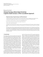
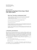
for convergence of the modified OTA-SRR algorithm are
presented in Appendix B and the algorithm is shown in
Figure 2.
4. SIMULATION MODEL
The simulation model considers an OFDMA-TDD network
with a total of 200 uniformly distributed users in a 19-
cell region, where each cell has a centrally-located BS.
However, a best-effort full-buffer system is in place, which
means that all users demand service at all times and the
quality of service (QoS) desired by a user corresponds to
the maximum data rate it can support. TDD is modeled
by assuming a single time slot, where each BS is assigned
to either UL or DL, and UL:DL ratios of 1:1, 1:6, and 6:1
are explored. In the case of RTSO, the UL/DL time slot
assignment is asynchronous among cells and the assignment
of each cell is random with probability depending on the
asymmetry ratio studied. When FSA is in place, all cells are
synchronously assigned UL or DL with the same probability,
thereby modeling symmetric traffic. Here, it should be noted
that channel allocation and scheduling are two disjoint
processes, so that after each BS has been assigned to either
UL or DL, scheduling takes place. A quasistatic model is
employed where the link gains between transmitters and
receivers remain unchanged for a time slot duration. A
BS-MS pair (i.e., a link) is formed based on minimum
path loss. The system parameters used in the simulation
are shown in Ta ble 1. Note that because of the snap-
shot nature of the simulation, MSs appear static. However,
Doppler frequency offset errors and offset errors due to
synchronization are accounted for by using constant offset
values. In particular, Doppler frequency offset corresponding
to a speed of 30 km/h and 50% synchornization offset are
6 EURASIP Journal on Wireless Communications and Networking
Initialization
Iteration k
= 0
Target initialization
γ
i
(0) = max{Γ}=γ
|Γ|
, ∀i ∈ N
End
False
While
λ
1
> 1−max
i∈N
η
i
p
Tr ue
Identify subcarrier j with worst link conditions,
i.e. find row with maximum row-sum:
j
= arg max
i∈N
N
i=1
Φ
i,j
assume user q uses subcarrier j
Adapt the modulation
scheme of subcarrier j:
reduce
γ
j
accordingly
If
γ
j
<γ
1
False
Recalculate
Φ
j
, η
j
, λ
1
k = k +1
Tr ue
Take away subcarrier j
from user q
If user q has zero
subcarriers left
False
Tr ue
Block user q
Find user r from the same BS as q
such that the interference on j is
minimized (minimum row-sum of Φ)
If q
= r
False
Tr ue
Assign subcarrier j to
user r with
γ
j
= γ
|Γ|
Delete row j and column j
of Φ, η
j
,andγ
j
(i.e. block
subcarrier j)
Recalculate
Φ
j
, η
j
, λ
1
k = k +1
Figure 2: Flowchart of the modified OTA-SRR algorithm.
used. The latter value is chosen to reflect a severe interference
scenario (e.g., [15]report
≈30% offset).
The small-scale fading effects are simulated via a Monte
Carlo method [16], which takes into consideration the effects
of Doppler shift and time delay. A power delay profile is
used corresponding to the specified delay spread in Tabl e 1
[17]. It is assumed that a proper cyclic prefix is in place such
that intersymbol interference (ISI) is avoided. The path loss
model to account for large-scale fading is chosen accordingly,
[18]—Terrain Category A (suburban), shown as follows:
P
L
= 20 log
10
4πd
0
f
c
+10ξ log
10
d
d
0
+ X
σ
[dB],
(16)
where d
0
is the reference distance in meters, f is the
carrier frequency, c is the speed of light (3
× 10
8
m/s),
ξ is the path loss exponent, d is the transmitter-receiver
Ellina Foutekova et al. 7
Table 1: Fixed parameters.
Number of BSs 19 Number of MSs 200
Cell radius 500 m Bandwidth 100 MHz
Number of subcarriers 2048 RMS delay spread 0.27 μs
Carrier frequency 1.9 GHz Maximum Doppler frequency 190 Hz
Maximum power per link 2 W Freq. offset due to synchronization 0.5
separation distance in meters, and X
σ
is a zero-mean
normally distributed random variable. The path loss in (16)
is lower-bounded by the free space path loss [9],
P
L
,givenby
P
L
= 20 log
10
4πf
c
+20log
10
(d)[dB]. (17)
Results for a system with NLOS conditions for all TDD
interference scenarios (MS
→ BS, BS → MS, BS → BS,
MS
→ MS) are compared against results for an equivalent
system where LOS in the case of BS
→ BS interference
is assumed (and NLOS for the remaining scenarios). The
path loss in the case of LOS is calculated using the free
spacepathlossmodel,givenin(17); and the worst-case
scenario is assumed with 100% probability of LOS. Adaptive
modulation is achieved with seven different modulation
schemes [19]giveninTable 2, based on the received SINR for
aBERof10
−7
(necessary for real-time services such as video
streaming). The corresponding data rates, Υ,arecalculated
using Υ
= MΥ
code
/T
s
,whereM is the number of bits per
symbol, Υ
code
is the code rate (here, 2/3), and T
s
is the
symbol time (including cyclic prefix of 20%). Note that the
cross and star constellations are QAM variations in order to
ensure robustness to interference, as described in [20, 21],
respectively.
5. RESULTS AND DISCUSSION
The algorithms implemented in this study are evaluated on
the basis of three metrics, viz spectral efficiency, subcarrier
utilization,anduser outage,describedbelow.Spectral effi-
ciency is the achieved system throughput divided by the
total bandwidth divided by the number of BSs, subcar rier
utilization is the number of subcarriers used in the system,
divided by the total number of subcarriers (number of
subcarriers per BS times the number of BSs), and user
outage is defined as the users not served (assigned zero
subcarriers) as a fraction of the total number of users in
the system. All metrics pertain to the whole system, that is,
UL and DL combined, unless stated otherwise. In addition,
as mentioned in Section 4,aTDDsystemissimulated
assuming a single time slot which is either assigned to UL
or DL traffic. This means that for every time slot a different
user distribution is analyzed. Since TDD can essentially
be characterized as a half-duplex system, this is deemed a
sensible approach in order to obtain insightful statistical
results on essential system metrics.
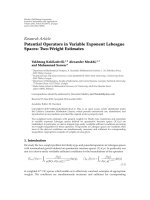
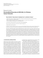
The variation of spectral efficiency with asymmetry and
LOS conditions for the BSs can be seen in Figures 3(a)
and 3(b) for the modified OTA-SRR and the modified GRP,
respectively. A clear trend can be observed for both schedul-
ing schemes. In particular, with an increase in the number of
time slots allocated to DL, the spectral efficiency increases
and reaches 90% of the theoretical maximum, which is
(Υ
max
× N
c
× B/W)/B = Υ
max
/W
c
= 4.44 bps/Hz/cell,
where W is the system bandwidth, W
c
is the bandwidth
per subcarrier, and Υ
max
is the maximum data rate per
subcarrier (as given in Table 2). Moreover, Figures 3(a)
and 3(b) show that LOS conditions among BSs degrade
performance significantly. For an asymmetry of 6:1 (UL:DL),
the spectral efficiency at the 50th percentile for OTA-SRR
and GRP decreases by
≈30% and ≈50%, respectively. In
contrast, the systems employing DL-favored asymmetry are
more robust to LOS among BSs. The difference between the
spectral efficiency achieved by the NLOS system and the
LOS system for an asymmetry of 1:6 (UL:DL) amounts to
≈8% and ≈6% at the 50th percentile for OTA-SRR and GRP,
respectively. This observation is as expected, due to the fact
that in DL-favored asymmetries, the occurrence of BS
→
BS interference is significantly limited. It is interesting to
note, however, that in terms of spectral efficiency, OTA-SRR
is considerably more robust to the detrimental BS
→ BS
interference during UL-favored asymmetries than GRP. The
algorithms’ “robustness” tends to equalize as the asymmetry
becomes in favor of DL. The fact that GRP is more sensitive
to interference can be explained by its mechanism: GRP
identifies the few best-placed users (in terms of path loss)
to be served with the highest achievable data rates. With a
deterioration in the interference conditions, there is a severe
reduction in the number of best-placed users and the data
rates that these users can achieve. In contrast, OTA-SRR
tries to serve all users, giving each user only the subcarriers
that they can utilize. Thus, OTA-SRR adapts to the overall
interference and that is why the degradation of performance
isnotassevereasinthecaseofGRP.
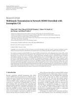
The outage results shown in Figures 4(a) and 4(b) for
OTA-SRR and GRP, respectively, display a similar trend
in terms of the comparative performance of the greedy
and fair algorithms. Furthermore, the results demonstrate
that allocating more resources to DL improves the outage
performance and this result is valid for both scheduling
algorithms. A comparison between the outage and spectral
efficiency results suggests that the relative performance
degradation due to LOS is smaller in the case of outage than
in the case of spectral efficiency. This is due to employing
adaptive modulation, which allows for various SINR levels to
be used before discarding a subcarrier. As a consequence, an
8 EURASIP Journal on Wireless Communications and Networking
Table 2: Adaptive modulation parameters for BER of 10
−7
.
Modulation scheme
4 8 16 32 64 128 256
QAM star QAM cross QAM cross QAM
Data rate 54.24 81.37 108.49 135.61 162.73 189.86 216.98 kbps
SINR 9 14 16 19 22.2 25 28.5 dB
3.532.521.510.5
Spectral efficiency (bps/Hz/cell)
NLOS
LOS
1:1 FSA
1:6
6:1
1:1
0
0.1
0.2
0.3
0.4
0.5
0.6
0.7
0.8
0.9
1
Cumulative probability
Empirical CDF: spectral efficiency (OTA-SRR)
(a) OTA-SRR
43.532.521.510.50
Spectral efficiency (bps/Hz/cell)
NLOS
LOS
1:1 FSA
1:6
6:1
1:1
0
0.1
0.2
0.3
0.4
0.5
0.6
0.7
0.8
0.9
1
Cumulative probability
Empirical CDF: spectral efficiency (GRP)
(b) GRP
Figure 3: Spectral efficiency [bps/Hz/cell] attained by the OTA-SRR and GRP for various UL:DL ratios for cases of LOS and NLOS among
BSs. The spectral efficiency is the total throughput in the system divided by the total bandwidth divided by the number of cells.
LOS system could serve approximately the same number of
users as an NLOS system (given that all other parameters are
the same), but with fewer subcarriers and significantly lower
data rates, due to the increased interference. Furthermore,
the outage results demonstrate that in the case of OTA-SRR
(at the 50th percentile), between
≈57% and ≈83% (at the
50th percentile) of the users are not served, whereas GRP
puts between
≈80% and ≈92% of the users into outage.
As expected, the fair algorithm offers service to a larger
population than the greedy algorithm. It should be noted
the outage metric is a relative metric, used for comparison
purposes only. The low percentage of served users is due to
the severe interference conditions considered.
The overall trends discussed above are also seconded by
the subcarrier utilization results presented in Figures 5(a)
and 5(b). In addition, it is interesting to note that at the 50th
percentile, OTA-SRR utilizes between
≈65% and ≈97% of
the available subcarriers, while GRP utilizes between
≈40%
and
≈90% of the subcarriers. The fact that OTA-SRR utilizes
more subcarriers is not surprising due to the algorithm’s fair
nature. As previously mentioned, OTA-SRR tries to serve as
many users as possible, while utilizing as many subcarriers
as possible, while GRP chooses only the “best-placed” users
with the “best” channels.
So far, the results have demonstrated superiority in the
performance of DL as compared to UL for all considered
metrics. In order to gain insight into the factors that influ-
ence the performance of UL and DL, the spectral efficiency
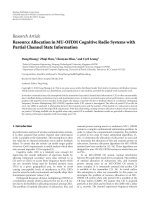
performance of UL and DL is studied separately. Results
are presented in Figure 6 assuming an UL:DL asymmetry of
1:1 for the following systems, employing RTSO: an OTA-
SRR system with NLOS conditions, an OTA-SRR system
with LOS conditions among BSs, an ideal OTA-SRR system,
and a benchmark system. The benchmark system considers
neither frequency offset errors nor Doppler errors, that is,
it is a purely orthogonal system where the only source of
interference is CCI. The resources are allocated randomly at
the beginning of each iteration and the SINR per subcarrier
is calculated. If the SINR of a particular subcarrier is below
the minimum required threshold (Ta ble 2), the subcarrier is
discarded and not utilized. If all subcarriers, allocated to a
particular user, are discarded, the user is put into outage.
The SINR of the subcarriers that can maintain a successful
link is used to determine their respective data rates and the
spectral efficiency of the system. The ideal system is also a
purely orthogonal system but, unlike the benchmark system,
has resource allocation and adaptive modulation in place.
Figure 6 suggests that the spectral efficiency achieved with
the benchmark system is the worst, which is as expected
because the absence of a scheduling mechanism does not
allow for frequency selectivity to be adequately exploited.
Moreover, in all cases, DL performs better than UL.
Ellina Foutekova et al. 9
0.90.850.80.750.70.650.60.550.50.450.4
Normalized number of users not served
NLOS
LOS
1:1 FSA
6:1
1:6
1:1
0
0.1
0.2
0.3
0.4
0.5
0.6
0.7
0.8
0.9
1
Cumulative probability
Empirical CDF: outage (OTA-SRR)
(a) OTA-SRR
10.950.90.850.80.750.7
Normalized number of users not served
NLOS
LOS
1:1 FSA
6:1
1:6
1:1
0
0.1
0.2
0.3
0.4
0.5
0.6
0.7
0.8
0.9
1
Cumulative probability
Empirical CDF: outage (GRP)
(b) GRP
Figure 4: Outage exhibited by the OTA-SRR and GRP for various UL:DL ratios for cases of LOS and NLOS among BSs. Outage is the ratio
of the number of users which are not served to the total number of users in the system.
10.90.80.70.60.50.4
Normalized number of utilized subcarriers
NLOS
LOS
1:1 FSA
1:6
1:1
6:1
0
0.1
0.2
0.3
0.4
0.5
0.6
0.7
0.8
0.9
1
Cumulative probability
Empirical CDF: subcarrier utilization (OTA-SRR)
(a) OTA-SRR
10.90.80.70.60.50.40.30.20.1
Normalized number of utilized subcarriers
NLOS
LOS
1:1 FSA
1:6
6:1
1:1
0
0.1
0.2
0.3
0.4
0.5
0.6
0.7
0.8
0.9
1
Cumulative probability
Empirical CDF : subcarrier utilization (GRP)
(b) GRP
Figure 5: Subcarrier utilization attained by the OTA-SRR and GRP for various UL:DL ratios for cases of LOS and NLOS among BSs.
Subcarrier utilization is the ratio of the number of subcarriers in the system that are used for transmission (i.e., the assigned data rate is
greater than (0) to the total number of subcarriers in the system, N
c
×B.
This is expected due to the presence of MAI in UL and
the lack thereof in DL. In addition, in UL, there is BS
→
BS and MS → BS interference, while BS → MS and MS
→ MS interference is characteristic for the DL. For the
benchmark system, the difference between UL and DL is
about 0.5 bps/Hz/cell at the 50th percentile. In the case of
the ideal system, DL only marginally outperforms UL, which
is as expected, because frequency selectivity is adequately
exploited. However, the difference in UL/DL performance
gets more pronounced as LOS conditions for the BSs and
offset errors are introduced, that is, in the case of the
LOS system and NLOS system, respectively. DL is more
favorable in terms of interference, due to the synchronous
nature of point-to-multipoint communication and the fact
that as the MSs are the receiving units, the detrimental
BS
→ BS LOS effects are not present. Thus, the system
10 EURASIP Journal on Wireless Communications and Networking
43.532.521.510.50
Spectral efficiency (bps/Hz/cell)
DL
UL
Ideal
NLOS
LOS
Benchmark
0
0.1
0.2
0.3
0.4
0.5
0.6
0.7
0.8
0.9
1
Cumulative probability
Empirical CDF: spectral efficiency (OTA-SRR)
Figure 6:ULandDLspectralefficiency attained by OTA-SRR for
UL:DL ratio of 1:1.
performance is expected to improve as the asymmetry is
shifted in favor of DL, which is in line with the observed
results (Figures 3(a) and 3(b)). It is interesting to note,
however, that contrary to intuition, DL LOS performs better
than DL NLOS. The reason lies in the mechanism of the
OTA-SRR algorithm, which operates on all subcarriers (in
the cells under consideration) simultaneously. As already
discussed, the UL overall performs worse than DL; and
this performance gap is enhanced when LOS conditions
are considered. Consequently, in an LOS system, the SINR
targets of UL subcarriers generally get down rated before
the DL subcarriers. As a result, UL subcarriers are discarded
before the DL subcarriers. This means that the dimension
of the normalized link gain matrix is decreased, which
in turn makes the convergence of the algorithm faster.
Fast convergence means fewer iterations of step-wise-rate
removal, which in turn means fewer-rate removals. As a
result, higher data rate per subcarrier is achieved, and, thus,
a system is obtained which achieves better spectral efficiency
on the DL than an equivalent NLOS system.
In an FSA network, on the other hand, LOS conditions
among BS do not cause interference, due to the synchronized
UL/DL switching point across the network. Thus, intuitively,
it is expected that a symmetric FSA scheme exhibits better
performance than an equivalent RTSO system, since it avoids
the detrimental BS
→ BS interference, as well as the MS →
MS interference. However, it can be observed that neither of
the schemes is strictly better than the other. For instance,
assuming OTA-SRR (Figure 3(a)), it can be found that for
RTSO, the probability that the spectral efficiency is greater
than 2.25 bps/Hz/cell is about 95%, whereas for FSA, this
probability is only about 75%. On the other hand, when
assuming a spectral efficiency of 3 bps/Hz/cell, it can be
found that the same probability for RTSO is 10%, whereas
the probability for FSA is 30%. As expected, their medians
generally coincide due to the fact that the rate of asymmetry
is the same, and, moreover, the FSA curve spans between the
1:6 (DL-dominated) NLOS and 6:1 (UL-dominated) NLOS
RTSO cases. The latter effect is attributed to the shifting of
more resources to UL (DL), which creates an interference
scenario (MS
→ BS (BS → MS)) similar to the UL (DL)
FSA. Furthermore, it can be observed from all results that
the cumulative density function (cdf) graphs for FSA are
generally spread out, whereas the cdf graphs for RTSO are
comparatively steeper. This means that RTSO offers a more
stable and robust QoS, while the QoS offered by the FSA is
with larger variation.
An interesting observation can be made with regard to
the outage results (Figures 4(a) and 4(b))—the FSA scheme
exhibits a “plateau” behavior (bimodal distribution). This
can be explained by the presence of MAI in UL, which
creates a significant gap between UL and DL performance.
Overall, it is observed that the RTSO can successfully exploit
interference diversity and thus outperform the FSA scheme
in certain scenarios for the same asymmetry. Moreover,
shifting more resources in favor of DL achieves better
performance than a symmetric FSA system. For example, at
aspectralefficiency of 3 bps/Hz/cell, the gain compared to a
symmetric UL/DL usage and FSA is about 20% (Figure 3(a)).
With respect to the comparative performance of the two
scheduling schemes presented in this paper, the results show
a similar trend in the explored metrics. However, GRP, which
allocates subcarrier, rate, and power in a greedy manner,
achieves only a marginal increase in spectral efficiency at
the cost of outage, as compared to the fair OTA-SRR. It is
interesting to relate these trends to a similar study done for
aCDMAsystemin[22] with the same cell radius, number
of cells, number of users as in the present study. In the
case of CDMA, the greedy GRP algorithm as compared to
the OTA-SRR scheme displays a twofold increase in terms
of total system data rate. At the same time, GRP serves
only 30% of the users which are served under the OTA-SRR
scheme. Thus, unlike CDMA, in an OFDMA system, the fair
OTA-SRR approach is more efficient than the greedy GRP
approach.
6. CONCLUSIONS
This paper explored UL/DL asymmetry interference aspects
in multicellular multiuser OFDMA-TDD systems consid-
ering both LOS and NLOS conditions among BSs, when
jointly applying channel allocation and user scheduling.
The results demonstrated that under RTSO, UL is the
performance limiting factor due to unfavorable interference
and the hazardous effect of LOS conditions among BSs. It
was, furthermore, shown that shifting more resources in DL
provides a system robust to these TDD-inherent problems,
which is particularly beneficial as future wireless services are
expected to be DL-dominated. Such a DL-favored scenario
attained up to 90% of the maximum spectral efficiency
achievable by the considered network. In addition, for the
same asymmetry, RTSO was found to offer a more stable
and robust QoS than FSA. The results also demonstrated
that, overall, the fair OTA-SRR scheduling algorithm was
more robust to the detrimental TDD-specific BS
→ BS
Ellina Foutekova et al. 11
interference than the greedy GRP algorithm. Furthermore,
the fair OTA-SRR served to up to
≈20% more users, utilizing
up to
≈25% more subcarriers, and still achieving spectral
efficiencies only marginally lower than those attained by
the GRP. Hence, RTSO when combined with OTA-SRR
fair scheduling allows the system to retain high spectral
efficiency while maintaining fairness in an OFDMA-TDD
cellular network with asymmetric traffic.
APPENDICES
A. GRP: TRANSMISSION AND POWER CONSTRAINTS
This section treats the derivation of the transmission and
power constraints for the GRP algorithm separately for the
cases of DL and UL.
A.1. DL transmission and power constraints
A power minimization problem subject to three constraints
was defined in Section 3.1. The first constraint is to choose
the SINR targets from the predefined target set Γ, the second
one is to limit the maximum allowed transmit power per
subcarrier to
p, and the third one is a constraint on the sum
of SINR targets. Given the first two constraints, GRP aims
(1) to maximize the achieved throughput by always assigning
the maximum possible SINR target from the target set, and
(2) to minimize the total power by using Corollary 1.In
order to define the DL GRP algorithm, first, the DL problem
statement is formulated and then the power constraint and
the throughput maximization condition for the case of DL
are derived.
The required power, P
k
, on a subcarrier k in the DL is
given by (A.1), which follows from making P
k
the subject
of (7). Note that because in DL perfect synchronization is
assumed, there is no MAI:
P
k
=
γ
k
G
k
|H
k
|
2
(P
CCI,k
+ n). (A.1)
Hence, the sum of the powers in a cell can be computed as
shown below:
N
c
k=1
P
k
=
N
c
k=1
γ
k
G
k
|H
k
|
2
(P
CCI,k
+ n). (A.2)
Now the objective function for DL can be expressed as
min
N
c
k=1
γ
k
G
k
|H
k
|
2
(P
CCI,k
+ n)
. (A.3)
The formulation in (A.3) is subject to a power constraint,
which can be expressed mathematically as shown below
using (A.1) and limiting the maximum transmit power per
subcarrier to
p:
p ≥
γ
k
G
k
|H
k
|
2
(P
CCI,k
+ n). (A.4)
Next, system throughput needs to be maximized. To formu-
late this for the case of DL, first, the upper bound on
γ
k
can
be expressed by rearranging (A.4) as follows:
γ
k
≤
pG
k
|H
k
|
2
P
CCI,k
+ n
. (A.5)
This effectively means that for given interference conditions
and channel state, the highest SINR target that can be
assigned (and achieved) is when the transmit power is
maximum. Hence, to maximize throughput, each subcarrier
must be assigned the maximum
γ
k
from the set Γ which
satisfies (A.5). Expressed mathematically, the condition for
throughput maximization is
max
γ
k
∈Γ
{γ
k
}≤
pG
k
|H
k
|
2
P
CCI,k
+ n
. (A.6)
The modified DL GRP algorithm is developed based on (A.4)
and (A.6) and is shown in Section 3.1.
A.2. UL transmission and power constraints
The approach used to formulate the UL GRP algorithm is
analogous to the approach used in the case of DL GRP in the
previous section.
The required power, P
k
, on a subcarrier k in UL is derived
using (6), where each side of (6) is multiplied by
|C
k,k
(z)|
2
.
For simplicity, the following notation is used:
x
k
= P
k
G
k
|H
k
|
2
|C
k,k
(z)|
2
, y
k
= P
CCI,k
+ n,
l
k
= γ
k
|C
k,k
(z)|
2
,
(A.7)
and (6)becomes:
l
k
=
x
k
k
/
∈s
x
k
+ y
k
,(A.8)
with both y
k
and l
k
fixed, and x
k
to be determined because
P
k
is of interest. Assuming that s is composed of only k, the
above equation can be rewritten as shown below. Note that
this is only a simplifying assumption and does not limit the
final result to a particular cardinality of s:
l
k
=
x
k
N
c
k
=1
x
k
−x
k
+ y
k
. (A.9)
By rearranging the abovementioned data, x
k
can be obtained
as
x
k
=
l
k
1+l
k
N
c
k
=1
x
k
+ y
k
. (A.10)
Next, (A.10) is summed over k and the result is used to
substitute
N
c
k
=1
x
k
in (A.10)toobtain
x
k
=
l
k
1+l
k
N
c
k
=1
(l
k
y
k
/(1 + l
k
))
1 −
N
c
k
=1
(l
k
/(1 + l
k
))
+ y
k
. (A.11)
12 EURASIP Journal on Wireless Communications and Networking
Now substitution for x
k
, y
k
,andl
k
and simplification yield
P
k
=
γ
k
(1 + γ
k
|C
k,k
(z)|
2
)G
k
|H
k
|
2
×
N
c
k
=1
(γ
k
|C
k,k
(z)|
2
(P
CCI,k
+n)/(1+γ
k
|C
k,k
(z)|
2
))
1 −
N
c
k
=1
(γ
k
|C
k,k
(z)|
2
/(1+γ
k
|C
k,k
(z)|
2
))
+P
CCI,k
+ n
.
(A.12)
Note that (A.12) contains
|C
k,k
(z)|
2
, which is the special case
of
|C
k,k
(z)|
2
when k and k
belong to the same user and are
the same subcarrier. (Technically, it could also be the case
that a subcarrier is reused at a given BS, but this situation
is not of interest, as reuse one is assumed here.) Whenever
that is the case, there are no errors due to Doppler and no
frequency offset errors, and in addition k
− k = 0, hence z
is 0. It can be shown that as z
→ 0, |C
k,k
(z)|
2
→ 1(refer
to Appendix C). Therefore, using
|C
k,k
(z)|
2
= 1, the required
power on a subcarrier k can be expressed as
P
k
=
γ
k
(1 + γ
k
)G
k
|H
k
|
2
×
N
c
k
=1
(γ
k
|C
k,k
(z)|
2
(P
CCI,k
+n)/(1+γ
k
|C
k,k
(z)|
2
))
1 −
N
c
k
=1
(γ
k
|C
k,k
(z)|
2
/(1+γ
k
|C
k,k
(z)|
2
))
+ P
CCI,k
+ n
.
(A.13)
Now using (A.13), the objective function for UL is formu-
lated as
min
N
c
k=1
γ
k
(1 + γ
k
)G
k
|H
k
|
2
×
N
c
k
=1
(γ
k
|C
k,k
(z)|
2
(P
CCI,k
+n)/(1 + γ
k
|C
k,k
(z)|
2
))
1−
N
c
k
=1
(γ
k
|C
k,k
(z)|
2
/(1+γ
k
|C
k,k
(z)|
2
))
+ P
CCI,k
+ n
.
(A.14)
As in DL, it is assumed that the maximum transmit power
allowed on each subcarrier is
p, however, it should be noted
that
p can be different for UL and DL. Then, the constraint
on the UL can be expressed as P
k
≤ p and using the
expression for P
k
in (A.13) and rearranging it, the UL power
constraint can be expressed as
N
c
k
=1
γ
k
|C
k,k
(z)|
2
1+γ
k
|C
k,k
(z)|
2
≤ 1−
γ
k
N
c
k
=1
(γ
k
|C
k,k
(z)|
2
(P
CCI,k
+n)/(1+γ
k
|C
k,k
(z)|
2
))
(1+γ
k
)pG
k
|H
k
|
2
−γ
k
(P
CCI,k
+n)
.
(A.15)
Now, note that for given
γ
k
, G
k
,and|H
k
|
2
, the expression in
(A.14) is minimized when 1
−
N
c
k
=1
(γ
k
|C
k,k
(z)|
2
/(1 +
γ
k
|C
k,k
(z)|
2
)) is maximized which is equivalent
to minimizing the left-hand side of (A.15), that is,
N
c
k
=1
(γ
k
|C
k,k
(z)|
2
/(1 + γ
k
|C
k,k
(z)|
2
)). This equivalence
holds because
N
c
k
=1
γ
k
|C
k,k
(z)|
2
1+γ
k
|C
k,k
(z)|
2
< 1, (A.16)
due to the fact that
γ
k
|C
k,k
(z)|
2
is always greater than or
equal to 0. Hence, the minimization of the left-hand side of
(A.15) can be expressed as
N
c
k
=1
γ
k
|C
k,k
(z)|
2
1+γ
k
|C
k,k
(z)|
2
≤ 1 −max
γ
k
N
c
k
=1
(Z/(1 + γ
k
|C
k,k
(z)|
2
))
(1 + γ
k
)pG
k
|H
k
|
2
−γ
k
(P
CCI,k
+ n)
,
(A.17)
where Z denotes
γ
k
|C
k,k
(z)|
2
(P
CCI,k
+ n).
The fraction on the right-hand side of the above
inequality is actually maximized when the largest possible
γ
k
is chosen from the set Γ such that (A.17) is satisfied. Based
on (A.15)and(A.17), a rate packing algorithm is developed
for the UL, given in Section 3.1. Note that for the special case
where all subcarriers in a cell belong to one user, there is no
MAI and the UL GRP algorithm is the same as the DL GRP
algorithm.
B. OTA-SRR: CONSTRAINTS AND
ALGORITHM CONVERGENCE
This section briefly reviews the OTA constraints and the
convergence issues pertaining to the OTA-SRR algorithm [7].
More detailed treatment can be found in [7].
The conditions for convergence of the system equation
(13) are outlined below:
(I
−Φ)
−1
= I + Φ + Φ
2
+ ···,
(I + Φ + Φ
2
+ ···)x = (1 + λ + λ
2
+ ···)x,
(B.1)
where x is the eigenvector corresponding to the eigenvalue λ
of Φ. The series in (B.1) converges if and only if λ<1and
this holds for any eigenvalue of Φ. Thus, (13) has a solution,
when λ
1
< 1.
In order to determine a feasible set of transmit powers,
let P
1
be the eigenvector corresponding to (1 − λ
1
), the
eigenvalue of (I
−Φ). Then, the system in (13)becomes
(1
−λ
1
)P
1
≥ η,
which is equivalent to
P
1
≥
η
1 −λ
1
. (B.2)
If P
max
is the vector of maximum transmit powers, P
1
must
satisfy
P
1
≤ P
max
. (B.3)
Ellina Foutekova et al. 13
Thus, based on (B.2)and(B.3), it follows that
P
max
≥
η
1 −λ
1
,(B.4)
with 0
≤ λ
1
≤ 1. The system constraint can now be expressed
by rearranging (B.4)as
1
−λ
1
≥ max
i∈N
η
i
p
. (B.5)
The modified OTA-SRR algorithm is illustrated by the
flowchart in Figure 2.
C. DERIVATION OF THE CYCLIC SINC FUNCTION
The following is a derivation of the cyclic sinc (or modified
Dirichlet) function, which accounts for the dependence of
the interference contribution from subcarrier k
to subcarrier
k on the
|k
−k|.
Based on the IFFT and FFT operations, the received
modulation symbol on subcarrier k (without noise), R
k
,can
be written as
R
k
=
1
N
c
N
c
−1
i=0
N
c
−1
k
=0
H
i,k
S
k
exp
j2πik
N
c
exp
−
j2πik
N
c
,
(C.1)
where j is the imaginary unit, S
k
is the transmit symbol
on subcarrier k,andH
i,k
is the channel transfer function
of subcarrier k. If one contributing propagation path is
assumed, the channel transfer function can be expressed as
H
i,k
= exp(jφ)exp
j2πi(ε
D
+ ω)
N
c
exp
−
j2πk
ε
τ
N
c
≡
H
k
exp
j2πi(ε
D
+ ω)
N
c
,
(C.2)
where ε
τ
is the relative propagation delay, and φ is the phase.
After substituting (C.2) into (C.1) and reordering result in
R
k
=
1
N
c
N
c
−1
i=0
N
c
−1
k
=0
H
k
exp
j2πi(ε
D
+ ω)
N
c
S
k
exp
j2πi(k
−k)
N
c
≡
1
N
c
N
c
−1
k
=0
H
k
S
k
N
c
−1
i=0
exp
j2πi(k
−k + ε
D
+ ω)
N
c
geometric series
.
(C.3)
The geometric series in (C.3) can be simplified. If 2π(k
−
k +ε
D
+ω)/N
c
= β, the geometric series representation yields
N−1
k=0
exp( jβk) =
1 −exp( jβN)
1 −exp( jβ)
≡ exp
j(N −1)β
2
sin(Nβ/2)
sin(β/2)
.
(C.4)
Using the result from (C.4), the cyclic sinc function C
k,k
(k
−
k + ε
D
+ ω)canbederivedas
C
k,k
(k
−k + ε
D
+ ω) =
1
N
c
sin(π(k
−k + ε
D
+ ω))
sin(π(k
−k + ε
D
+ ω)/N
c
)
×exp
jπ(k
−k+ε
D
+ω)(N
c
−1)
N
c
,
(C.5)
such that (C.3)becomes
R
k
=
N
c
−1
k
=0
H
k
S
k
C
k,k
(k
−k + ε
D
+ ω). (C.6)
Thereceivedsymbolin(C.6) includes both an interference
component and a useful component, and can be written in
terms of desired signal power and interference power (in
Watts) as
R
k
=
N
c
−1
k
=0, k
/
=k
|H
k,k
|
2
P
k
G
k,k
|C
k,k
(k
−k + ε
D
+ ω)|
2
interference
+ |H
k
|
2
P
k
G
k
|C
k,k
(k −k + ε
D
+ ω)|
2
useful signal
.
(C.7)
However, (C.7)modelsageneralcaseofMAI,whichin
Section 2 is straightforwardly tailored to account for multiple
subcarriers per link and also to account for CCI. It should
be noted that Doppler offset and frequency synchronization
errors in the desired signal are not considered as perfect
synchronization is assumed, hence, the argument of
|C
k,k
(k−
k + ε
D
+ ω)|
2
is 0. Using (C.5) and noting that for small
α,sin(α)
≈ α, it can be shown that as the argument of
|C
k,k
(k −k + ε
D
+ ω)|
2
goes to 0, |C
k,k
(k −k + ε
D
+ ω)|
2
goes
to 1. Hence, the useful (desired) signal power per subcarrier,
R
k
, is expressed as
R
k
= P
k
G
k
|H
k
|
2
[W]. (C.8)
ACKNOWLEDGMENTS
The authors would like to thank the anonymous reviewers
for the very useful and constructive comments and sug-
gestions. The reviewers input clearly helped to improve
the manuscript. The authors would also like to thank the
School of Engineering and Electronics at The University of
Edinburgh, Edinburgh, UK, for the financial support of this
work.
REFERENCES
[1] C. Y. Wong, R. S. Cheng, K. B. Letaief, and R. D. Murch,
“Multiuser OFDM with adaptive subcarrier, bit, and power
allocation,” IEEE Journal on Selected Areas in Communications,
vol. 17, no. 10, pp. 1747–1758, 1999.
[2] T. Keller and L. Hanzo, “Adaptive modulation techniques for
duplex OFDM transmission,” IEEE Transactions on Vehicular
Technology, vol. 49, no. 5, pp. 1893–1906, 2000.
14 EURASIP Journal on Wireless Communications and Networking
[3] L. Yan, Z. Wenan, and S. Junde, “An adaptive subcarrier, bit
and power allocation algorithm for multicell OFDM systems,”
in Proceedings of the Canadian Conference on Electrical and
Computer Engineering (CCECE ’03), vol. 3, pp. 1531–1534,
Montreal, Canada, May 2003.
[4]H.RohlingandR.Gr
¨
unheid, “Performance comparison of
different multiple access schemes for the downlink of an
OFDM communication system,” in Proceedings of the 47th
IEEE Vehicular Technology Conference (VTC ’97), vol. 3, pp.
1365–1369, Phoenix, Ariz, USA, May 1997.
[5] H. Haas and S. McLaughlin, Eds., Next Generation Mobile
Access Technologies: Implementing TDD, Cambridge University
Press, Cambridge, UK, 2008.
[6] H. Haas, P. K. Jain, and B. Wegmann, “Capacity improvement
through random timeslot opposing (RTO) algorithm in
cellular TDD systems with asymmetric channel utilisation,” in
Proceedings of the 14th International Symposium on Personal,
Indoor and Mobile Radio Communications ( PIMRC ’03), vol.
2, pp. 1790–1794, Beijing, China, September 2003.
[7] S. Ginde, A game-theoretic analysis of link adaptation in cellular
radio networks, M.S. thesis, Virginica Polytechnic Institute and
State University, Blacksburg, Va, USA, May 2004.
[8]F.BerggrenandS L.Kim,“Energy-efficient control of rate
and power in DS-CDMA systems,” IEEE Transactions on
Wireless Communications, vol. 3, no. 3, pp. 725–733, 2004.
[9]T.S.Rappaport,Wireless Communications: Principles and
Practice, Prentice Hall PTR, Upper Saddle River, NJ, USA, 2nd
edition, 2001.
[10] IST-2003-507581 WINNER, “D1.3 v1.0 Final Usage Sce-
narios,” June 2005, />older.html.
[11] W. Yu, G. Ginis, and J. M. Cioffi,“Anadaptivemultiuserpower
control algorithm for VDSL,” in Proceedings of the Global
Telecommunications Conference (GLOBECOM ’01), vol. 1, pp.
394–398, San Antonio, Tex, USA, November 2001.
[12] G. Scutari, D. P. Palomar, and S. Barbarossa, “Asynchronous
iterative waterfilling for Gaussian frequency-selective inter-
ference channels: a unified framework,” in Proceedings of the
Information Theory and Applications Wor kshop (ITA ’07),pp.
349–358, Lake Tahoe, Calif, USA, September 2007.
[13] J. Zander and S L. Kim, Radio Resource Manageme n t for
Wireless Networks, Artech House, Boston, Mass, USA, 2001.
[14] F. R. Gantmacher, Matrix Theory, vol. 2, Chelsea, New York,
NY, USA, 1974.
[15] M. Speth, S. A. Fechtel, G. Fock, and H. Meyr, “Optimum
receiver design for wireless broad-band systems using OFDM.
I,” IEEE Transactions on Communications, vol. 47, no. 11, pp.
1668–1677, 1999.
[16] P. H
¨
oher, “A statistical discrete-time model for the WSSUS
multipath channel,” IEEE Transactions on Vehicular Technol-
ogy, vol. 41, no. 4, pp. 461–468, 1992.
[17] J. Medbo and P. Schramm, “Channel Models for HIPERLAN
2,” ETSI/BRAN document no. 3ERIO85B, 1998., September
2006, />[18] V. Erceg, L. J. Greenstein, S. Y. Tjandra, et al., “An empirically
based path loss model for wireless channels in suburban envi-
ronments,” IEEE Journal on Selected Areas in Communications,
vol. 17, no. 7, pp. 1205–1211, 1999.
[19] K. J. Hole, H. Holm, and G. E. Øien, “Adaptive multidi-
mensional coded modulation over flat fading channels,” IEEE
Journal on Selected Areas in Communications,vol.18,no.7,pp.
1153–1158, 2000.
[20] W. T. Webb, L. Hanzo, and R. Steele, “Bandwidth-efficient
QAM schemes for Rayleigh fading channels,” in Proceedings
of the 5th International Conference on Radio Receivers and
Associated Systems, pp. 139–142, Cambridge, UK, July 1990.
[21] G. Forney Jr., R. Gallager, G. Lang, F. Longstaff,andS.
Qureshi, “Efficient modulation for band-limited channels,”
IEEE Journal on Selected Areas in Communications, vol. 2, no.
5, pp. 632–647, 1984.
[22] E. Foutekova, P. Agyapong, B. Ghimire, H. Venkataraman, and
H. Haas, “Scheduling in cellular CDMA-TDD networks,” in
proceedings of the 64th IEEE Vehicular Technology Conference
(VTC ’06), pp. 727–731, Montreal, Canada, September 2006.