Báo cáo hóa học: " Synthesis and Characterization of ZnO Nanowire–CdO Composite Nanostructure" docx
Bạn đang xem bản rút gọn của tài liệu. Xem và tải ngay bản đầy đủ của tài liệu tại đây (446.55 KB, 6 trang )
NANO EXPRESS
Synthesis and Characterization of ZnO Nanowire–CdO
Composite Nanostructures
Karuppanan Senthil Æ Youngjo Tak Æ
Minsu Seol Æ Kijung Yong
Received: 1 June 2009 / Accepted: 17 July 2009 /Published online: 30 July 2009
Ó to the authors 2009
Abstract ZnO nanowire–CdO composite nanostructures
were fabricated by a simple two-step process involving
ammonia solution method and thermal evaporation. First,
ZnO nanowires (NWs) were grown on Si substrate by
aqueous ammonia solution method and then CdO was
deposited on these ZnO NWs by thermal evaporation of
cadmium chloride powder. The surface morphology and
structure of the synthesized composite structures were
analyzed by scanning electron microscopy, X-ray diffrac-
tion and transmission electron microscopy. The optical
absorbance spectrum showed that ZnO NW–CdO com-
posites can absorb light up to 550 nm. The photolumines-
cence spectrum of the composite structure does not show
any CdO-related emission peak and also there was no band
gap modification of ZnO due to CdO. The photocurrent
measurements showed that ZnO NW–CdO composite
structures have better photocurrent when compared with
the bare ZnO NWs.
Keywords Zinc oxide Á Cadmium oxide Á Nanowires Á
Composites Á Optical absorbance
Introduction
Zinc oxide (ZnO) is one of the most important materials for
the optoelectronic applications because of its wide band
gap (3.37 eV) and high-exciton binding energy (60 meV)
that is much larger than other semiconductor materials such
as ZnSe (22 meV) and GaN (25 meV). ZnO nanostructures
have been extensively investigated in the past decade due
to their interesting optical [1, 2] and electrical properties
[3–6]. These nanostructures have potential applications as
UV light sources, photodetectors, sensors, photocatalysts,
solar cells, field effect transistors, field emission devices
and piezoelectric devices [5–12]. Among the various ZnO
nanostructures, ZnO nanowires have attracted much
attention because of their unique material properties and
well-developed synthesis methods. Various methods have
been employed to fabricate ZnO nanowires including gas-
phase methods such as metal-organic chemical vapor
deposition (MOCVD) [13], evaporation [14], pulsed-laser
deposition [15], solution-phase methods such as chemical
bath deposition (CBD) [16], electrochemical deposition
[17] and hydro-thermal method [18]. Especially, solution-
phase methods are appealing because of the low growth
temperatures, potentials for scaling up and capability of
producing high-density arrays [19].
Recently, ZnO nanowire arrays have been applied as a
transparent electrode in the solar energy devices due to their
high surface area and good vertically aligned electrical
pathways, which are expected to increase the efficiency of
these photoelectric devices [11, 20, 21]. However, ZnO can
only absorb a small portion of the solar spectrum in the
visible region due to its wide band gap. To further widen the
useable wavelength range and improve the efficiency of
ZnO-based photodevices, a narrow band gap material should
be alloyed or composited with ZnO. In principle, the
K. Senthil
Center for Information Materials, Pohang University of Science
and Technology (POSTECH), San 31, Hyoja-dong, Nam-gu,
Pohang 790-784, South Korea
Y. Tak Á M. Seol Á K. Yong (&)
Department of Chemical Engineering, Pohang University of
Science and Technology (POSTECH), San 31, Hyoja-dong,
Nam-gu, Pohang 790-784, South Korea
e-mail:
123
Nanoscale Res Lett (2009) 4:1329–1334
DOI 10.1007/s11671-009-9401-z
coupling of ZnO with a narrow band gap material, can reduce
its band gap, extend its absorption range to visible-light
region, promote electron-hole pair separation under irradi-
ation and consequently achieve a higher efficiency for the
ZnO-based photodevices. In recent years, heterostructures of
ZnO with metals or semiconductors have attracted much
attention because of their enhanced optical and photocata-
lytic properties [22–30].
CdO, an n-type II–VI semiconductor, has attracted
considerable attention for various optoelectronic devices
due to its high electrical conductivity (even without dop-
ing), high carrier concentration and high optical transmit-
tance in the visible region of the solar spectrum. By
alloying with CdO, which has a cubic structure and a
narrower direct band gap of 2.2–2.5 eV, the band gap of
ZnO can be red-shifted to a blue or even a green spectral
range. Wang et al. [31] have shown that UV near-band-
edge emission was red-shifted to 407 nm (3.04 eV) from
386 nm (3.21 eV) with the increasing Cd content for their
quasi-aligned ZnCdO nanorods. Up to our knowledge,
there are no reports available on the heterostructures of
ZnO nanostructures with CdO. In the present study, we
report the synthesis and characterization of ZnO nanowire–
CdO composite structures by a two-step process involving
chemical solution method and thermal evaporation. The
synthesized ZnO NW–CdO composite structures showed
enhanced optical absorbance in the visible region.
Experiment
ZnO NW–CdO composite structures were fabricated on
silicon substrates by using a two-step process. First, ZnO
NWs were grown on Si substrates using the previously
reported ammonia solution method [32, 33]. A 25 nm ZnO
buffer film was coated on the Si substrate by sputtering a
ZnO target at room temperature and then was air-annealed
at 800 °C for 1 h. After cooling to room temperature, the
substrates were immersed in a 10 mM Zn(NO
3
)
2
Á6H
2
O
(98%, Aldrich) aqueous solution where pH was adjusted to
11 by adding the ammonia solution [28 wt% of NH
3
(Aldrich) in water], and the solution was heated at 95 °C
for 10 h. After the growth, the substrate was removed from
the solution, rinsed with the deionized water and then dried
by nitrogen blow. Then ZnO NW–CdO composite struc-
tures were grown by thermal evaporation of CdCl
2
powder
in argon atmosphere using a conventional horizontal tube
furnace. Pure CdCl
2
powder was deposited in the middle of
the alumina boat and the ZnO NW substrate was placed on
the top of the boat with the ZnO nanowire surface facing
the powder. The alumina boat was then placed at the uni-
form-temperature zone of the furnace and heated to 500–
550 ° C (ramp rate *12 °C/min) with a constant argon
flow of 100 sccm. The temperature was maintained at 500–
550 ° C for about 1 h and then the furnace was allowed to
cool normally to room temperature before taking the
sample out for characterization. When CdCl
2
is evaporated,
CdO is formed on ZnO NWs by taking the residual oxygen
present in the furnace.
The surface morphology, structure and composition of the
as-grown ZnO NW and ZnO NW–CdO composites were
characterized by field emission scanning electron micros-
copy (FE-SEM; JEOL JSM 330F), X-ray diffraction (XRD;
Rigaku D-Max1400, Cu Ka radiation k = 1.5406 A
˚
),
Raman spectroscopy (SENTERRA dispersive Raman micro-
scope, 532 nm laser wavelength), high-resolution transmis-
sion electron microscopy (HR-TEM; JEOL 2100F) and
energy-dispersive X-ray spectroscopy (EDX) measure-
ments. The optical absorbance (diffuse reflectance spec-
troscopy—DRS) measurements were carried out using a
UV-visible spectrophotometer. The photoluminescence
measurements were carried out at room temperature using
He–Cd laser (325 nm) as the excitation source. The photo-
current measurements were carried out in a typical three-
electrode cell (Potentiostat/Galvanostat, Model 263A) that
included a Pt counter electrode, a saturated calomel refer-
ence electrode and a working electrode made from ZnO NW
or ZnO NW–CdO composites on the ITO substrate. A 1 M
Na
2
S solution was used as the electrolyte. The working
electrode was illuminated from front side with a solar-
stimulated light source (AM1.5G filtered, 100 mW/cm
2
,
91160, Oriel).
Results and Discussion
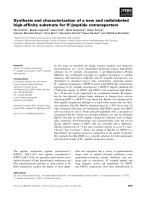
Figure 1a, b shows the low and high magnification cross-
sectional FE-SEM images of ZnO NW array grown on Si
substrate. The grown nanowire array was highly dense and
vertically well aligned. The nanowires were about 50–
100 nm in diameter and 4–5 lm in length. CdCl
2
powder
(0.4 and 0.6 g) was evaporated on these nanowire arrays to
obtain ZnO NW–CdO composite structures. Figure 1c–f
shows SEM images of the ZnO NW–CdO composite
structures grown using 0.4 and 0.6 g of CdCl
2
powder,
respectively. It can be seen that the surface of the ZnO NW
becomes rough and CdO layer was found deposited mainly
on the tip of the ZnO nanowires. With the increase of
CdCl
2
powder, the amount of CdO deposited on the tips
increased.
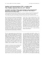
X-ray diffraction patterns obtained from the as-grown
ZnO NWs and ZnO NW–CdO composite structure were
shown in Fig. 2a, b, respectively. As-grown ZnO NW
sample showed major XRD peaks at 2h of 34.54° and
62.98° that can be indexed to reflections from (002) and
(103) planes of hexagonal ZnO, respectively, according to
1330 Nanoscale Res Lett (2009) 4:1329–1334
123
JCPDS no. 36-1451. The peaks from (101), (102) and (110)
planes of ZnO were also observed. XRD pattern obtained
from the ZnO NW–CdO composite structure showed
additional peaks from (111), (200), (220) and (311) planes
corresponding to cubic CdO (JCPDS no. 05-0640) beside
hexagonal ZnO peaks. The ZnO-related XRD peaks
observed for the ZnO NW–CdO composite structure were
slightly deviated from the peaks observed for the ZnO NW
sample. This suggests that there might be a very small
ZnCdO phase at the interface.
Figure 3 shows the Raman spectrum obtained from the
as-grown ZnO NW and ZnO NW–CdO composite struc-
ture. The Raman spectrum from the as-grown ZnO NW
sample (Fig. 3a) exhibited E
2
(high) and A
1
(LO) modes at
437 and 581 cm
-1
, respectively. The Raman spectrum was
recorded with the incident light exactly perpendicular to
the top of the sample surface (the incident light is parallel
to the c-axis of the ZnO NWs). In this configuration, only
the E
2
and A
1
(LO) modes are allowed, whereas the
A
1
(TO) and E
1
(TO) modes are forbidden according to
the Raman selection rules. The presence of LO modes and
the absence TO modes in the Raman spectrum further
confirms that the grown nanowires are vertically aligned
with c-axis oriented. The peak at 275 cm
-1
could be
attributed to the B
1
(low) silent Raman mode [34]. The
Raman spectrum from the ZnO NW–CdO composite
structure (Fig. 3b) is similar like ZnO NW sample and
showed Raman peaks only from ZnO and do not show any
CdO-related Raman peak. The assignment of Raman mode
of CdO is very difficult and it is known that mostly CdO is
Raman inactive [35]. This could be attributed to the
absence of CdO-related Raman peak for our composite
structures. A slight shift in E
2
(high) Raman mode was
Fig. 1 SEM images (cross-
sectional and tilted view)
obtained from a, b ZnO NWs;
c, d ZnO NW–CdO composites
(0.4 g of CdCl
2
) and e, f ZnO
NW–CdO composites (0.6 g of
CdCl
2
)
Fig. 2 X-ray diffraction pattern obtained from the a ZnO NWs and b
ZnO NW–CdO composites
Nanoscale Res Lett (2009) 4:1329–1334 1331
123
reported for the case of ZnCdO nanorods [36]. In our case,
we could not observe any shift in that Raman mode
because the obtained nanostructures are ZnO NW–CdO
composite structure.
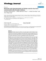
The detailed microscopic structure and chemical com-
position of the ZnO NW–CdO composite structures were
analyzed by using a high-resolution scanning transmission
electron microscope (HR-STEM). Figure 4a shows the low
magnification TEM image of the ZnO NW–CdO composite
structure showing a single ZnO nanowire with CdO layer
coated only on the upper part of the nanowire up to a
certain length (a few hundreds nm) from the tip. It was
observed that the CdO-coated surface was rougher than
that of the bare ZnO NW surface. Figure 4b, c shows the
HR-TEM lattice images from the ZnO and CdO regions of
ZnO NW–CdO composite structure, respectively. There
might be a very small ZnCdO phase at the interface. But
we could not identify the ZnCdO phase clearly from the
HR-TEM analysis. The lattice image from the ZnO NW
showed clear lattice fringes confirming the single crystal-
line ZnO. The measured lattice spacing of the crystallo-
graphic plane is 0.252 nm, which corresponds well with the
(002) plane (0.25 nm) of hexagonal ZnO. The lattice
spacing measured from the CdO lattice image is 0.267 nm
and this value corresponds well with the d-value
(0.271 nm) of (111) plane of cubic CdO. Figure 5a shows
TEM image from the ZnO NW–CdO composite structure
and Fig. 5b–d shows EDX elemental mapping corre-
sponding to Zn, O and Cd, respectively. The elemental
mapping further confirms that CdO is coated only on the tip
of the ZnO NWs.
Figure 6 shows the DRS spectra of the as-grown ZnO
NWs and ZnO NW–CdO composite structures. Becasue
CdO is a narrow band gap material, it is expected that
optical absorbance region will be extended to the visible
region for the ZnO NW–CdO composite structures. The
optical absorbance edge for the ZnO NWs is found to be
about 400 nm, whereas the ZnO NW–CdO composites
absorb light up to 550 nm in the visible region. The inset of
the Fig. 6 shows the digital photograph images of the ZnO
NW and ZnO NW–CdO composite samples. We can
observe that the color of the ZnO NW samples changed
from gray to yellow-orange color after CdO deposition.
Figure 7 shows the room temperature PL spectra from
the ZnO NWs annealed in H
2
atmosphere at 400 °C and
ZnO NW–CdO composite structures. The PL spectrum
from the ZnO NWs shows an intense UV emission peak at
377 nm without any defect emissions. This result suggests
that the grown ZnO NWs have high crystalline quality. The
PL spectrum from the ZnO NW–CdO composites showed a
UV emission peak at 381 nm, and no emission band from
CdO was observed. The UV emission peak is attributed to
the near-band-edge exciton emission. It has been reported
that the UV emission peak has been red-shifted to 407 nm
with increasing Cd content for the case of ZnCdO nanorods
indicating a band gap modulation [31]. For our composite
nanostructures, the peak position of the near-band-edge
emission is slightly red-shifted and also the intensity is
reduced when compared with the UV emission peak of the
ZnO nanowire. The slight red-shift in the emission peak
could be attributed to the existence of ZnCdO phase at the
interface. The reduced PL intensity could be attributed to
the quenching effects. A similar behavior has been reported
for the CdS nanoparticle modified ZnO nanowalls [37].
The rock salt CdO is known to have at least one indirect
optical transition with the band gap energy of 0.8 eV below
the direct absorption edge at 2.4 eV [38]. The absence of
any CdO-related PL peak in our case may be attributed to
this indirect nature of the rock salt CdO structure.
Fig. 3 Raman spectra of a ZnO NWs and b ZnO NW–CdO
composites
Fig. 4 a TEM image obtained from the ZnO NW–CdO composite
and b, c HRTEM lattice images obtained from the ZnO and CdO
regions, respectively
1332 Nanoscale Res Lett (2009) 4:1329–1334
123
Preliminary experiments were carried out using ZnO
NW–CdO composites on ITO substrate as the electrode
material in the photoelectrochemical cell (PEC). The pho-
toresponse measurements were carried out at 0 V. The dark
and photocurrent characteristics (current vs. time) of the
ZnO NWs and ZnO NW–CdO composites measured at 0 V
are given in Fig. 8. A higher photocurrent was observed for
the ZnO NW–CdO composites when compared with the
bare ZnO NWs. The optical absorption capability in the
visible region could be attributed to the higher photocurrent
for the ZnO NW–CdO composite structures. Systematic
Fig. 5 a TEM image of the
ZnO NW–CdO composite
structure showing CdO
deposition only on the tip of the
ZnO nanowire and their
corresponding EDX elemental
mapping of b Zn, c O and d Cd,
respectively
Fig. 6 Diffuse reflectance spectra (DRS)ofa ZnO NWs and b ZnO
NW–CdO composites. The inset shows the digital photograph of the
ZnO NW and ZnO NW–CdO composite samples
Fig. 7 Room temperature photoluminescence spectra obtained from
the a ZnO NWs and b ZnO NW–CdO composites
Nanoscale Res Lett (2009) 4:1329–1334 1333
123
investigations are now in progress to improve the photo-
conversion efficiency of these composite structures by
optimizing the various parameters such as substrate mate-
rial (Pt-coated Si or FTO), electrolytes and CdO deposition
conditions. The studies on photodegradation of organic
dyes are also now in progress to explore the photocatalytic
properties of these composite structures.
Conclusions
We synthesized ZnO NW–CdO composite structures using
a simple two-step process involving ammonia solution
method followed by thermal evaporation. SEM and TEM
analysis indicated that CdO was deposited mainly on the
tip of the ZnO nanowires. XRD analysis of the composite
structures showed additional diffraction peaks corre-
sponding to cubic CdO, apart from the signals from the
hexagonal ZnO. The ZnO NW–CdO composite structures
showed enhanced optical absorption extending to about
550 nm in the visible region. PL measurements do not
show any band gap modification for the composite struc-
tures. The higher visible-light absorption capability of
these composite structures can be applied to enhance their
photoelectrochemical and photocatalytic properties. Sys-
tematic studies are now in progress to explore these
properties.
Acknowledgments This work was supported by grant no. R01-
2006-000-10230-0 (2006) from the Korea Science and Engineering
Foundation, grant no. RTI04-01-04 from the Regional Technology
Innovation Program of the Ministry of Commerce, Industry and
Energy (MOCIE) and the Korean Research Foundation Grants funded
by the Korean Government (MOEHRD; KRF-2005-005-J13101) and
grant no. KRF-2007-521-D00118.
References
1. A.B. Djurisic, Y.H. Leung, Small 2, 944 (2006)
2. M.H. Huang, S. Mao, H. Feick, H. Yan, Y. Wu, H. Kind,
E. Weber, R. Russo, P. Yang, Science 292, 1897 (2001)
3. M.H. Zhao, Z.L. Wang, S. Mao, Nano Lett. 4, 587 (2004)
4. Z.Y. Fan, J.G. Lu, Appl. Phys. Lett. 86, 032111 (2005)
5. X. Wang, J.L.J. Song, Z.L. Wang, Science 316, 102 (2007)
6. C.J. Lee, T.J. Lee, S.C. Lyu, Y. Zhang, H. Ruh, H.J. Lee, Appl.
Phy. Lett. 81, 3648 (2002)
7. Z.L. Wang, J. Phy. Cond. Matt. 16, R829 (2006)
8. L. Schmidt-Mende, J.L. MacManus-Driscoll, Mater. Today 10,
40 (2007)
9. N. Kouklin, Adv. Mater. 20, 2190 (2008)
10. Y. Qin, X. Wang, Z.L. Wang, Nature 451, 809 (2008)
11. J.B. Baxter, E.S. Aydil, Appl. Phys. Lett. 86, 053114 (2005)
12. Q. Wan, Q.H. Li, Y.J. Chen, T.H. Wang, X.L. He, J.P. Li,
C.L. Lin, Appl. Phy. Lett. 84, 3654 (2004)
13. W.I. Park, G.C. Yi, M. Kim, S.J. Pennycook, Adv. Mater. 14,
1841 (2002)
14. S.Y. Bae, C.W. Na, J.H. Kang, J.G. Park, J. Phys. Chem. B 109,
2526 (2005)
15. Y. Zhang, R.E. Russo, S.S. Mao, Appl. Phy. Lett. 87, 133115
(2005)
16. J. Song, S.J. Lim, J. Phys. Chem. C 111, 596 (2007)
17. J.B. Cui, U.J. Gibson, J. Phys. Chem. B 109, 22074 (2005)
18. C.H. Lu, L.M. Qi, J.H. Yang, L. Tang, D.Y. Zhang, J.M. Ma,
Chem. Comm. 3551 (2006)
19. L.E. Greene, B.D. Yuhas, M. Law, D. Zitoun, P. Yang, Inorg.
Chem. 45, 7535 (2006)
20. C. Levy-Clement, R. Tena-Zaera, M.A. Ryan, A. Katty,
G. Hodes, Adv. Mater. 17, 1512 (2005)
21. Y. Gao, M. Nagai, T.C. Chang, J.J. Shyue, Crys. Growth Des. 7,
2467 (2007)
22. W.Q. Zhang, Y. Lu, T.K. Zhang, W.P. Xu, M. Zhang, S.H. Yu, J.
Phys. Chem. C 112, 19872 (2008)
23. Y. Zheng, L. Zheng, Y. Zhan, X. Lin, Q. Zheng, K. Wei, Inorg.
Chem. 46, 6980 (2007)
24. J. Nayak, S.N. Sahu, J. Kasuya, S. Nozaki, Appl. Surf. Sci. 254,
7215 (2008)
25. Y. Tak, H. Kim, D. Lee, K. Yong, Chem. Comm. 4585 (2008)
26. T. Gao, Q.H. Li, T.H. Wang, Chem. Mater. 17, 887 (2005)
27. R. Tena-Zaera, A. Katty, S. Bastide, C. Levy-Clement, Chem.
Mater. 19, 1626 (2007)
28. Z. Wang, B. Huang, Y. Dai, X. Qin, X. Zhang, P. Wang, H. Liu,
J. Yu, J. Phys. Chem. C 113, 4612 (2009)
29. D. Lin, H. Wu, W. Zhang, H. Li, W. Pan, Appl. Phys. Lett. 94,
172103 (2009)
30. Y. Tak, S.J. Hong, J.S. Lee, K. Yong, Cryst. Growth Des. 9
, 2627
(2009)
31. F.Z. Wang, Z.Z. Ye, D.W. Ma, L.P. Zhu, F. Zhuge, H.P. He,
Appl. Phys. Lett. 87, 143101 (2005)
32. Y. Tak, K. Yong, J. Phys. Chem. C 112, 74 (2008)
33. Y. Tak, K. Yong, J. Phys. Chem. B 109, 19263 (2005)
34. F.J. Manjon, B. Mari, J. Serrano, A.H. Romera, J. Appl. Phys. 97,
053516 (2005)
35. Z.V. Popovic, G. Stanisic, D. Stojanovic, R. Kostic, Phys. Stat.
Sol. 165(b), K109 (1991)
36. F. Wang, H. He, Z. Ye, L. Zhu, H. Tang, Y. Zhang, J.Phys. D 38,
2919 (2005)
37. F. Fang, D.X. Zhao, B.H. Li, Z.Z. Zhang, J.Y. Zhang, D.Z. Shen,
Appl. Phys. Lett. 93, 233115 (2008)
38. A.B.M.A. Ashrafi, H. Kumano, I. Suemune, Y.W. Ok,
T.Y. Seong, Appl. Phys. Lett. 79, 470 (2001)
Fig. 8 The photoresponse characteristics of a ZnO NWs and b ZnO
NW–CdO composites
1334 Nanoscale Res Lett (2009) 4:1329–1334
123