Báo cáo hóa học: " Research Article Iterative Multiview Side Information for Enhanced Reconstruction in Distributed Video Coding" pot
Bạn đang xem bản rút gọn của tài liệu. Xem và tải ngay bản đầy đủ của tài liệu tại đây (2.98 MB, 17 trang )
Hindawi Publishing Corporation
EURASIP Journal on Image and Video Processing
Volume 2009, Article ID 591915, 17 pages
doi:10.1155/2009/591915
Research Article
Iterative Multiview Side Information for Enhanced
Reconstruction in Distributed Video Coding
Mourad Ouaret, Fr
´
ed
´
eric Dufaux, and Touradj Ebrahimi (EURASIP Member)
Multimedia Signal Processing Group (MMSPG), Ecole Polytechnique F
´
ed
´
erale de Lausanne (EPFL), 1015 Lausanne, Switzerland
Correspondence should be addressed to Mourad Ouaret, mourad.ouaret@epfl.ch
Received 30 May 2008; Revised 13 October 2008; Accepted 15 December 2008
Recommended by Anthony Vetro
Distributed video coding (DVC) is a new paradigm for video compression based on the information theoretical results of Slepian
and Wolf (SW) and Wyner and Ziv (WZ). DVC entails low-complexity encoders as well as separate encoding of correlated video
sources. This is particularly attractive for multiview camera systems in video surveillance and camera sensor network applications,
where low complexity is required at the encoder. In addition, the separate encoding of the sources implies no communication
between the cameras in a practical scenario. This is an advantage since communication is time and power consuming and requires
complex networking. In this work, different intercamera estimation techniques for side information (SI) generation are explored
and compared in terms of estimating quality, complexity, and rate distortion (RD) performance. Further, a technique called
iterative multiview side information (IMSI) is introduced, where the final SI is used in an iterative reconstruction process. The
simulation results show that IMSI significantly improves the RD performance for video with significant motion and activity.
Furthermore, DVC outperforms AVC/H.264 Intra for video with average and low motion but it is still inferior to the Inter No
Motion and Inter Motion modes.
Copyright © 2009 Mourad Ouaret et al. This is an open access article distributed under the Creative Commons Attribution
License, which permits unrestricted use, distribution, and reproduction in any medium, provided the original work is properly
cited.
1. Introduction
Multiview video is attractive for a wide range of appli-
cationssuchasfreeviewpointtelevision(FTV)[1]and
video surveillance camera networks. The increased use of
multiview video systems is mainly due to the improvements
in video technology. In addition, the reduced cost of cameras
encourages the deployment of multiview video systems.
FTV is one of the promising applications of multiview.
FTV is a 3D multiview system that allows viewing the
scene from a view point chosen by the viewer. Video
surveillance is another area where multiview can be beneficial
for monitoring purposes. In addition, the multiple views
can be used to improve the performance of event detection
and recognition algorithms. However, the amount of data
generated by multiview systems increases rapidly with the
number of cameras. This makes data compression a key issue
in such systems.
In DVC [2], the source statistics are exploited at the
decoder by computing the SI of the WZ frame using different
techniques. In this paper, a review of different SI techniques
for multiview DVC is first provided, including a thorough
evaluation of their estimation quality, complexity, and RD
performance. Moreover, all the SI techniques are combined
in the ground truth (GT) fusion, which combines the
different SIs using the original WZ frame at the decoder.
Even though this is not feasible in practice, it gives the
maximum achievable DVC performance. Further, a new
technique called iterative multiview side information (IMSI)
is proposed to improve the DVC RD performance especially
for video with significant motion. IMSI uses an initial SI
to decode the WZ frame and then constructs a final SI
which is used in a second reconstruction iteration. Finally,
the performance of multiview DVC is compared with respect
to AVC/H.264 [3] Intra, Inter No Motion (i.e., zero motion
vectors), and Inter Motion.
The paper is structured as follows. First, the paradigm of
distributed video coding is presented in Section 2.Multiview
DVC is described in Section 3, whereas, Section 4 reviews
the different intercamera estimation techniques. The IMSI
2 EURASIP Journal on Image and Video Processing
R
Y
(bits)
H(Y )
H(Y
|X)
H(X
|Y) H(X) R
X
(bits)
R
X
+ R
Y
= H(X,Y)
Vanishing probability error
No errors
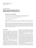
Figure 1: Achievable rate region defined by the Slepian-Wolf
bounds.
technique is proposed in Section 5. Then, the test material
and simulation results are presented and discussed in
Section 6. Finally, some concluding remarks are drawn in
Section 7.
2. Distributed Video Coding (DVC)
2.1. Theoretical DVC. DVC is the result of the information-
theoretic bounds established for distributed source coding
(DSC) by Slepian and Wolf [4] for lossless coding, and
by Wyner and Ziv [5] for lossy coding with SI at the
decoder. Lossless DSC refers to two correlated random
sources separately encoded and jointly decoded by exploiting
the statistical dependencies.
If we consider two statistically dependent random
sequences X and Y,ratesR
X
and R
Y
can be achieved by
entropy coding such that R
X
≥ H(X)andR
Y
≥ H(Y), where
H(X)andH(Y ) are the entropies of X and Y,respectively.
The Slepian-Wolf theorem proves that a better rate can be
achieved with joint decoding and gives tighter bounds for
the total rate R
X
+ R
Y
. The admissible rate region established
by SW, which corresponds to the shaded area depicted in
Figure 1,isdefinedby
R
X
≥ H(X|Y), R
Y
≥ H(Y|X),
R
X
+ R
Y
≥ H(X,Y).
(1)
Decoding with SI is considered as a special case of DSC.
In this case, the source X depends on some SI Y,which
corresponds to the black dot on the region border in
Figure 1. Later on, Wyner and Ziv established bounds for
lossy compression with SI at the decoder as an extension
to the Slepian and Wolf theorem. In this case, the source X
is encoded without having access to the SI Y. On the other
hand, the decoder has access to the SI to produce X with a
certain distortion D.
2.2. Practical DVC. Figure 2 shows the DVC architecture
used in this work [6].
At the encoder, the frames are separated into two sets.
The first one is the key frames which are fed to a conventional
AVC/H.264 Intra encoder. The second set is the WZ frames.
The latter are transformed and then quantized prior to WZ
encoding. The same 4
× 4 separable integer transform as in
AVC/H.264 is used with properties similar to the discrete
cosine transform (DCT) [7]. Then, the same bands are
grouped together and the different bit planes are extracted
and then fed to a turbo encoder [8]. The latter offers near-
channel capacity error correcting capability. Furthermore, a
cyclic redundancy check (CRC) [9] is computed for each
quantized bit plane and transmitted to the decoder. The
frequency of the key frames is defined by the group of
pictures (GOPs).
At the decoder, the key frames are conventionally
decoded and then used to generate the SI for the WZ decoder.
In the monoview case, motion compensation temporal
interpolation (MCTI) [10] is used to generate the SI. For
this purpose, MCTI uses the key frames to perform motion
estimation. The resulting motion vectors are interpolated at
midpoint as illustrated in Figure 3.
A virtual channel is used to model the correlation
between the DCT coefficients of the original and SI frames. It
is shown that the residual of the DCT coefficients follows the
Laplacian distribution [2]. The reconstruction process [11]
uses the SI along with decoded bins to recover the original
frame up to a certain quality. The decoder accepts the SI DCT
value as a reconstructed one if it fits into the quantization
interval corresponding to the decoded bin. Otherwise, it
truncates the DCT value into the quantization interval. This
DVC scheme is decoder driven as the request for parity bits
from the encoder is performed via a feedback channel until
successful decoding. The decoding is considered successful if
the decoded bit plane error probability is lower than 10
−3
and
its CRC matches the one received from the encoder.
The multiview DVC scheme used in this research is
exactly the same as the monoview DVC described above
except for the SI extraction module as it is explained further
in Section 3.
3. Multiview DVC (MDVC)
MDVC is a solution that allows independent encoding of the
cameras and joint decoding of the different video streams as
shown in Figure 4.
It differs from monoview DVC in the decoder. More
precisely, the SI is constructed not only using the frames
within the same camera but using frames from the other
cameras as well.
A fusion technique between temporal and homography-
based side information is introduced in [12]. The fusion
considers the previous and the forward frames as predictors
of the WZ frame. The logical operation OR is used to com-
bine the different predictors for each pixel. In other words,
MCTI is chosen if it is a better predictor than homography
for at least one of the two frames. Otherwise, homography
is chosen as predictor as illustrated in Figure 5. The results
in [12] report that the fusion outperforms monoview DVC
EURASIP Journal on Image and Video Processing 3
Conventional
video encoder
Minimum
rate
distortion
Side
information
extraction
Virtual
channel
model
WZ and
conventional
data splitting
Conventional
video decoder
Soft input
computation
Channel
decoder
Decoder
succ. /
failure
Bit
ordering
Channel
encoder
Buffer
Wyner-Ziv encoder Wyner-Ziv decoder
Video out
Video in
T − 1
Q
− 1and
reconst.
T
TQ
Figure 2: Conventional DVC architecture.
t +1
t
t
− 1
Key frame
Wyner-Ziv frame
Key frame
Figure 3: Motion compensation temporal interpolation (MCTI).
MV is a motion vector in the forward direction.
Joint
DVC
decoder
DVC
encoder
DVC
encoder
DVC
encoder
.
.
.
.
.
.
Figure 4: MDVC scheme. The different views are separately
encoded and jointly decoded.
by around 0.2∼0.5 dB for video with significant motion for a
spatial resolution of 256
× 192 at 15 fps for a three cameras
setup. In the latter, only the central camera contains WZ
For each pixel, if MCTI
predicts better the previous
OR the forward frame, use
MCTI otherwise use
homography
Compare MCTI SI
with previous and
forward key frames
Compare
homography SI
with previous and
forward key frames
Previous and
foward key frames
MCTI SI Homography SI
Figure 5: Decoder-driven fusion [12].
frames while the side ones are conventionally coded in Intra
mode. This is called decoder-driven fusion.
Artigas et al. [13] proposed two novel fusion techniques
between temporal and intercamera side information. In the
first technique, temporal motion interpolation is performed
between the previous and the forward frames from the side
cameras. The result is subtracted from the current frame
and then thresholded to obtain a binary mask. The latter
is projected to the central camera to perform the fusion
as shown in Figure 6(a). The second algorithm uses the
previous and the forward frames as predictors for the current
frame on the side cameras to compute a reliability mask.
The latter is projected to the central camera and used to
perform the fusion as depicted in Figure 6(b).Itisreported
that the fusions improve the average PSNR of the SI using
high resolution video (1024
× 768 at 15 fps). On the other
hand, the RD performance of DVC is not investigated, and
the simulations are run using the originals, which is in
practice not feasible. Moreover, depth maps are required to
perform the intercamera estimation which is a hard problem
for complex real-world scenes.
4 EURASIP Journal on Image and Video Processing
WZ
camera
Intra
camera
Frame k
− 1
Frame k
Frame k +1
Frame k − 1
Frame k
Frame k +1
Projection
−
Motion
estimation and
interpolation
(a) Motion estimation is performedonthesidecameratocomputea
fusion mask for the central camera
WZ
camera
Intra
camera
Frame k
− 1
Frame k
Frame k +1
Frame k − 1
Frame k
Frame k +1
Projection
−
−
(b) Frame difference w.r.t the previous and forward frames
on the side camera is used to compute the fusion mask
Figure 6: Fusion techniques proposed by Artigas et al. [13].
In [14], the wavelet transform is combined with turbo
codes to encode a multiview camera array in a distributed
way. At the decoder, a fusion technique is introduced to com-
bine temporal and homography-based side information. It
thresholds the motion vectors and the difference between the
corresponding backward and forward estimations to obtain
a fusion mask. The mask assigns the regions with significant
motion vector and estimation error to homography SI, and
the rest is assigned to temporal SI (i.e., regions with low
motion and relatively small prediction error). It is reported
that the hybrid SI outperforms the temporal one by around
1.5 dB in PSNR. In addition, it outperforms H.263+ Intra by
around 4.0
∼7.0 dB. A video content with spatial resolution
320
× 240 is used in the evaluation.
Further, a flexible estimation technique that can jointly
utilize temporal and view correlations to generate side
information is proposed in [15]. More specifically, the
current pixel in the WZ frame is mapped using homography
to the left and right camera frames. Then, AVC/H.264
decision modes are applied to the pixel blocks in the left and
right camera frames. If both resulting modes are intermodes,
the SI value is taken from temporal SI. Otherwise, it is taken
from homography SI. The simulation results show that this
technique significantly outperforms conventional H.263+
Intra coding. Nevertheless, comparison with AVC/H.264
Intra would be beneficial as it represents state-of-the-art for
conventional coding.
A fusion technique based on some prior knowledge
of the original video is introduced in [16]. This is called
encoder-driven fusion. Initially, a binary mask is calculated
at the encoder as illustrated in Figure 7. It is compressed
using a bilevel image compression [17] encoder and then
transmitted to the decoder.
For each pixel, the mask informs the decoder whether
the previous or the forward pixel is a better predictor of the
same pixel in the original frame to perform fusion at the
decoder (Figure 8). The results report a maximum gain up
to 1.0 dB over monoview DVC in the same conditions as
[12]. Furthermore, there is a slight increase in the encoder
With respect to the WZ pixel
output:
1 if previous pixel is closer
or
0 if forward pixel is closer
Previous key WZ frame Forward key
Binary mask
Figure 7: The encoder-driven fusion at the encoder side [16].
complexity as it has to perform the additional task of
compressing the binary mask.
In [18], coding of multiview image sequences with video
sensors connected to a central decoder is investigated. The N
sensors are organized in an array to monitor the same scene
from different views as shown in Figure 9.Onlydecoders
2toN perform DVC using disparity compensated output
of decoder 1. In addition, the video sensors are able to
exploit temporal correlation using a motion compensated
lifted wavelet transform [19] at the encoder. The proposed
scheme reduces the bit rate by around 10% by performing
joint decoding when compared to separate decoding for
video content at 30 fps and 256
× 192 spatial resolution.
Finally, ways of improving the performance of multiview
DVC are explored in [20]. Several modes to generate
homography-based SI are introduced. The homography is
estimated using a global motion estimation technique. The
results show an improvement of SI quality by around 6.0 dB
and a gain in RD performance by around 1.0
∼2.0dB for
video content with a spatiotemporal resolution of 256
×
192 at 15 fps. However, the reported results assume an
ideal fusion mask, which requires the knowledge of the
original at the decoder. This is not feasible in a practical
scenario.
EURASIP Journal on Image and Video Processing 5
Binary mask
If mask is equal to one
use the previous pixel
as reference otherwise
use the forward pixel
Output the pixel value
that is closer to the
reference
Reference
frame
Previous key
frame
Forward key
frame
Homography SI MCTI SI
Figure 8: The encoder-driven fusion at the decoder side [16].
U
n
U
i
U
1
U
n
U
i
U
1
Encoder N
Encoder i
Encoder 1
Decoder N
Decoder i
Decoder 1
.
.
.
Disparity
compensation
Disparity
compensation
Figure 9: Distributed coding scheme with disparity compensation
at the central decoder [18].
4. Intercamera Prediction
In this section, different SI techniques for multiview DVC
are reviewed. The different techniques are described for 3
cameras setup, where the central camera is predicted from
both neighboring cameras, as depicted in Figure 10.
4.1. Dispar ity Compensation View Prediction (DCVP).
DCVP [16] is based on the same idea as MCTI, but the
motion compensation is performed between the frames from
the side cameras. A slight modification is applied to DCVP to
improve the SI quality. Instead of interpolating the motion
vectors at midpoint, an optimal weight is computed in
[16]. For this purpose, the first frame of each camera is
conventionally decoded. Then, motion compensation is per-
formed between the side camera frames. The motion vectors
are weighted with the weights 0.1, 0.2, ,0.9. Further, the
SI PSNR is computed for each weight. The weight with
maximum PSNR is maintained and used for the rest of
the sequence. Nevertheless, the SI generated by DCVP has
usually a poorer quality than the one generated by MCTI.
This is due to the larger disparity between the side camera
frames when compared to the one between the previous and
forward frames.
4.2. Homography. The homography, H,isa3
× 3matrix
transforming one view camera plane to another one as
shown in Figure 11.
It uses eight parameters a, b, c, d, e, f, g,andh.The
homography maps a point (x
1
, y
1
) from one plane to a point
(x
2
, y
2
) in the second plane up to a scale λ such that
λ
⎛
⎜
⎝
x
2
y
2
1
⎞
⎟
⎠
=
⎛
⎜
⎝
abc
de f
gh1
⎞
⎟
⎠
⎛
⎜
⎝
x
1
y
1
1
⎞
⎟
⎠
. (2)
This model is suitable when the scene can be approximated
by a planar surface, or when the scene is static and the
camera motion is a pure rotation around its optical center.
The homography can be calculated using various techniques.
In this work, we consider a global motion estimation
technique introduced in [21] to compute the homography.
The parameters are calculated such that the sum of squared
differences E between the reference frame and the warped
side frame is minimized:
E
=
N
i=1
e
2
i
with e
i
= I
w
x
w
i
, y
w
i
−
I
x
i
, y
i
,(3)
where I
w
(x
w
i
, y
w
i
)andI(x
i
, y
i
) are the pixels from the
warped and reference frames, respectively. The problem
is solved using the Levenberg-Marquardt gradient descent
algorithm to iteratively estimate the parameters. To remove
the influence of such outliers, a truncated quadratic is used.
In other words, only pixels for which the absolute value of the
error term is below a certain threshold are taken into account
in the estimation process, other pixels are ignored. Therefore,
the algorithm will count mainly for global motion
E
=
N
i=1
ρ
e
i
with ρ
e
i
=
e
2
i
if
e
i
≥
T else 0, (4)
where T is a threshold.
In multiview DVC, the warped frame is computed from
the left (H
L
)andright(H
R
) camera frames as shown in
Figure 12. Therefore, three side information are possible.
The one entirely warped from each side camera and the
average (H) of both side cameras. The latter is the only one
considered in this work.
The advantage of this technique is that once the homog-
raphy relating the central camera with the side ones is
estimated, computing the SI becomes very simple in terms
6 EURASIP Journal on Image and Video Processing
IIII
WZ I WZ I
IIII
Joint decoding
1
2
3
Figure 10: The multiview camera setup considered in this work. I stands for intraframe and WZ for Wyner-Ziv frame.
H
Warped frame Reference frame
Figure 11: Homography matrix H relating one view to another.
of computational complexity when compared to techniques
based on exhaustive block-based motion estimation. More-
over, this technique is suitable for scenarios, where the global
motion is highly dominant with respect to local variations
as it would generate a good estimation in this case. On
the other hand, if the scene has multiple significant objects
moving in different directions, the estimation would be of a
poor quality as the technique would only account for global
motion.
4.3. View Synthesis Prediction (VSP). The previously men-
tioned techniques do not take advantage of some important
features of multiview. That is, the speed at which an object
is moving in a view depends on its depth information. In
addition to this, rotations, zooms, and different intrinsic
parameters are difficult to model using a motion vector,
which is a simple translational model. Furthermore, the
homography tries to estimate a global motion and ignores
local motion using a truncated error function, which is not
the case of VSP [22]. In the latter, the camera parameters,
intrinsic and extrinsic, are used to predict one camera view
from its neighbors.
For simplicity, the case of one neighboring camera is
considered as shown in Figure 13. The view from camera c
2
can be synthesized from camera c
1
. Each pixel I(c
1
, x, y)from
camera c
1
is projected into the 3D world reference using its
depth information:
λ
⎛
⎜
⎝
x
y
1
⎞
⎟
⎠
=
A
RT
01
⎛
⎜
⎜
⎜
⎝
X
3D
Y
3D
Z
3D
1
⎞
⎟
⎟
⎟
⎠
,(5)
where A is the intrinsic parameters matrix, and R and T are
the rotation and translation matrices with respect to the 3D
world reference. Moreover, the depth information is equal to
Z
3D
, which corresponds to the Z coordinate of the point in
the 3D world coordinates. It is substituted in (5), and the
resulting system is solved for X
3D
and Y
3D
. Then, the 3D
point is projected back to the 2D plane of camera c
2
. This
process is performed for each pixel of camera c
1
.
In the multiview camera setup used in this research, the
pixel in the central camera is mapped to both side cameras.
The pixel value is taken as average of both side camera pixels.
The drawback of this technique is the difficulty to
estimate depth for real-world complex scenes. In addition,
the quality of the SI depends on the precision of the camera
calibration and depth estimation.
4.4. View Morphing (VM). Image morphing can generate
compelling 2D transitions between images. However, dif-
ferences in object pose or viewpoint often cause unnatural
distortions in image morphs. Using basic principles of
projective geometry, one can perform a simple extension to
image morphing that correctly handles 3D projective camera
and scene transformations. The view morphing requires
the computation of the fundamental matrix, which is the
algebraic representation of epipolar geometry. Suppose that
we have a point P in the 3D world coordinates. This point is
visible in both cameras with optical centers C
0
and C
1
as P
0
and P
1
, respectively. The three points P, C
0
,andC
1
define
a plane called the epipolar plane π. The line intersection
of the epipolar plane with each image plane is called an
epipolar line as shown in Figure 14. The fundamental matrix
is derived from the mapping between a point in one camera
and its epipolar line in the other camera. Therefore, matching
points should be calculated between the two images.
VM [23] is used to get an image from a virtual camera
that could be placed between two real cameras as shown
in Figure 15. The input of the view morphing algorithm
is two images from real cameras and information about
the correspondences between regions in the two images
or projection matrices of the side cameras from 3D world
coordinates to 2D coordinates in each camera plane. The
output of the algorithm is a synthesized image (i.e., a view
from the virtual camera).
TheVMofavirtualcamerawithopticalC
s
is illustrated
in Figure 16. Initially, both images I
0
and I
1
are warped across
the scanlines to get
I
0
and
I
1
, respectively, which are in the
same plane. The latter are morphed across the position of
EURASIP Journal on Image and Video Processing 7
H
L
H
R
Left view
at time t
Right view
at time t
t
Figure 12: Homography-based SI.
x
y
z
Depth
c
1
c
2
2D point
2D point
Projectfrom2Dto3D
Projectfrom2Dto3D
3D point in the world
coordinate
Figure 13: View synthesis prediction.
C
1
C
0
P
1
P
0
P
Epipolar plane π
Figure 14: The epipolar line and plane.
Right camera Virtual camera
Left camera
Figure 15: The virtual camera in view morphing.
the virtual camera C
s
to get
I
s
. Finally,
I
s
is unwarped to get
I
s
. As in the case of DCVP, an optimal weight s is computed
for the virtual camera C
s
such that the PSNR is maximized
for the warped frame with respect to the central view frame.
The problem with VM is that it works very well for simple
scenes with a central object infront a uniform background.
In this case, extracting matched feature points with a high
degree of accuracy from the scene is simple as these points
are used to compute the fundamental matrix. On the other
hand, VM fails for real-world scenes as the matched feature
points task becomes a more challenging task.
4.5. Multiview Motion Estimation (MVME). MVME [24]
finds the motion vectors in the side cameras and then applies
them to the central camera to estimate the WZ frame as
shown in Figure 17. The motion vectors computed in one
view should be transformed before being used in another
view. Nevertheless, they can be directly reused if all the
cameras lie in the same plane and point in the same direction.
First, a disparity vector
dv is obtained by block-based full
search between the WZ and the intracameras for frame k
− 1.
The vector
dv estimates the location of each block from the
WZ camera in the intracamera. Then, the motion vector
mv
is computed by searching in frame k in the intracamera for
the best match for the block obtained in the previous step
as illustrated in Figure 18(a). Finally, the motion vector
mv is
applied to the aligned block in frame k in the WZ camera as
depicted in Figure 18(b).
Figure 19 shows the possible motion paths to estimate
the WZ frame, which are a total of 8 paths, 4 inner
paths, and 4 outer paths, each generating one estimate. The
inner paths are computed as described above by performing
8 EURASIP Journal on Image and Video Processing
C
1
C
s
C
0
I
1
I
1
I
s
I
s
I
0
I
0
P
Figure 16: VM of a virtual camera with optical center C
s
.
disparity estimation followed by motion estimation on the
intracamera (Figure 19(a)). The outer paths are computed by
doing the opposite of inner paths computation, starting with
motion estimation on the intracamera followed by disparity
estimation (Figure 19(b)). The simplest way to generate the
final SI is by taking the average of these estimates. A better
strategy is to compute a reliability measure for each path on
a block or pixel basis and weight the estimates before taking
the sum. For this purpose, mean square error (MSE) or mean
absolute difference (MAD) computed between the original
and the candidate blocks is used as a reliability measure.
5. Iterative Multiview Side Information (IMSI)
We initially introduced iterative SI for the monoview sce-
nario in [25], where the final SI depends not only on the
key frames but also on the WZ bits as well. This final SI is
used to refine the reconstruction of the decoded WZ frame.
This is done by running the reconstruction process in a
second iteration to enhance the quality of the decode frame.
The process of IMSI is illustrated in Figure 20.IMSIdiffers
from monoview iterative SI [25] in the fact that the initial
SI depends on the input video in the multiview case. In the
latter, the refinement process is applied to all the blocks,
while a threshold is used to select the refined blocks based
on the estimation error in [25].
Initially, the reconstruction process of DVC is described
in this section. Then, IMSI is introduced.
5.1. DVC Reconstruction. This stage in the decoding pro-
cess is opposite to the quantization step at the encoder.
After turbo decoding, the decoder knows perfectly the
quantization bin of each decoded band. Relying on the
assumption that the WZ frame is correlated with the SI, the
reconstruction block uses the SI along with decoded bins
to improve the reconstruction quality as described in [11].
The principal consists in either accepting an SI value as a
reconstructed value if it fits into the quantization interval
corresponding to the decoded bin or truncating the SI
value into this quantization interval. The reconstruction is
performed independently for every transform coefficient of
every band.
Let Y be the SI value, d the decoded quantized index, Δ
the quantization step, and
X the reconstructed value. In the
case of the DC band, the reconstructed value
X is computed
as
X =
⎧
⎪
⎪
⎨
⎪
⎪
⎩
Y if dΔ ≤ Y ≤ (d +1)Δ,
dΔ if Y<dΔ,
(d +1)Δ if Y>(d +1)Δ.
(6)
For the AC bands, the reconstructed value
X is computed in
a similar way. The only difference is that a quantizer with a
dead zone is used for the AC coefficients as they take positive
and negative values. On the other hand, the DC coefficient
takes only positive value.
5.2. IMSI for Enhanced Reconstruction. Hereafter, the pro-
posed IMSI is described.
(i) First, the initial SI to use in the WZ frame decoding
is chosen depending on the nature of the video. This
is done by computing the average luma variation per
pixel between the key frames at the decoder, which is
compared to a threshold. If it is below the threshold,
the motion is considered not significant and MCTI is
used as the initial SI. Otherwise, MVME is taken as
initial SI. This is motivated by the results presented
further in Section 6.2. Namely, MCTI shows better
estimation quality for low-motion video content. On
the other hand, MVME is shown to have a better
performance for video with significant motion.
(ii) WZ decoding is performed using the initial SI,
which implies turbo decoding followed by a first
reconstruction stage.
(iii) The decoded WZ frame from the first stage is
then predicted by block-based motion search and
compensation as in conventional video coding using
four references: the previous, forward, left camera,
and right camera frames. More specifically, for each
block in the decoded frame, the best matching block
with minimum distortion is selected using the square
absolute difference (SAD) as the distortion metric as
shown in Figure 21. This generates a final SI.
(iv) Finally, the final SI is used in a second iteration in the
reconstruction block.
It is important to stress the fact that this method does not
use the original WZ but rather the decoded WZ frame using
the initial SI. IMSI is expected to be efficient in situations
where motion is significant as the difference in estimation
quality between the initial and final SIs is more important.
The reason is that the final SI is highly correlated with
the WZ frame in the case of high activity video content.
Therefore, most of the SI values map into the decoded bin
EURASIP Journal on Image and Video Processing 9
WZ
camera
Intra
camera
Intra
camera
Frame k
− 1
Frame k
Frame k − 1
Frame k
Frame k − 1
Frame k
Motion
estimation
Motion
compensation
Motion
compensation
Motion
estimation
Motion
vectors
Motion
vectors
Figure 17: Conceptual scheme. Motion vectors are found in the intracamera and used in the WZ camera.
Wyner-Ziv
camera
Intra
camera
Frame k
− 1
Frame k
dv
mv
(a)
Wyner-Ziv
camera
Frame k
− 1
Frame k
mv
(b)
Figure 18: (a) Motion estimation scheme and (b) motion compensation scheme [24].
in the reconstruction process (i.e., the SI value is taken as the
reconstructed value). This produces a better reconstruction
with lower distortion as less SI values are truncated into
the quantization interval, when compared to the initial
reconstruction phase, using the initial SI.
The improvement for low-motion video is negligible as
both side information, initial and final, are close in terms of
estimation quality.
IMSI generates a better estimation of the WZ frame than
the initial SI, since it uses the decoded WZ frame from the
first iteration to compute the estimation. On the other hand,
the price to pay for this good estimation is the initial WZ rate
spent to initially decode the WZ frame. In addition, there is
an increase in the decoder complexity due to the additional
motion search task.
6. Simulation Results
6.1. Test Material and Evaluation Methodolog y. The sequen-
ces Breakdancer s, Ballet, and Uli shown in Figure 22 are used
for evaluating the performance of the different SI techniques.
Breakdancers and Ballet contain significant motion. This
makes the motion estimation a difficult and challenging task.
On the other hand, Uli is a conference-like video sequence,
which contains more or less static video content. The spatial
resolution is 256
× 192 for all the sequences. The temporal
resolutions are 15 fps for Breakdancers and Ballet,and25fps
for Uli.
In this paper, three camera views are used, and the
performance is evaluated only for the central camera. For
DVC simulations, the DISCOVER codec [6] is run with the
following settings.
(i) Only luminance data is coded.
(ii) The central camera is the only one containing WZ
frames. The side cameras (i.e., left and right) are
conventionally encoded in the intramode, while the
central one contains WZ frames, as depicted in
Figure 10.
(iii) Four RD points are computed per SI. They corre-
spond to the following quantization matrices:
QI
1
=
⎛
⎜
⎜
⎜
⎝
32800
8 000
0 000
0 000
⎞
⎟
⎟
⎟
⎠
, QI
2
=
⎛
⎜
⎜
⎜
⎝
32 16 8 4
16840
8400
4000
⎞
⎟
⎟
⎟
⎠
,
QI
3
=
⎛
⎜
⎜
⎜
⎝
64 16 8 8
16884
8844
8440
⎞
⎟
⎟
⎟
⎠
, QI
4
=
⎛
⎜
⎜
⎜
⎝
128 64 32 16
64 32 16 8
32 16 8 4
16840
⎞
⎟
⎟
⎟
⎠
.
(7)
Each element of the matrices corresponds to the
number of quantization levels to the corresponding
10 EURASIP Journal on Image and Video Processing
I
WZ
I
C
C
C
C
C
C
I
WZ
I
C
C
C
C
C
C
Intra cam WZ cam Intra cam
Frame k − 1
Frame k
Frame k +1
(a) Inner paths
I
WZ
I
C
C
C
C
Intra cam WZ cam Intra cam
C
C
Frame k − 1
Frame k
Frame k +1
(b) Outer paths
Figure 19: The 8 possible paths when using two intracameras and two reference frames in each camera [24].
Final SI
construction
Initial SI
Initially
decoded
WZ frame
Final SI
DCT
IDCT
DCT
IDCT
Average pixel
variation between
key frames
Reconstruction
Reconstruction
Finally
decoded
WZ frame
MCTI
or
MVME
Key and side
camera frames
Turbo
decoder
WZ bits
Figure 20: The IMSI generation process.
coefficient band. For example, the DC coefficient has
32, 32, 64, and 128 quantization levels, respectively,
in the 1st, 2nd, 3rd, and 4th RD points, and so on.
(iv) The same quantization parameter (QP) is used for
the side cameras and the key frames of the central
camera. A QP is defined per quantization matrix such
that the decoded key and WZ frames have a similar
quality.
(v)TheGOPsizeisequalto2.
For AVC/H.264 coding, the publicly available reference
software (JM 11.0) [26] is used with the following settings:
(a) Intra, Inter No Motion, and Inter Motion modes. For
the Inter No Motion mode, each motion vector is
equal to zero, which means that each block in a P
frame is predicted from the colocated block in the
previous I frame. For the Inter Motion mode, the
motion search range is set to 32. In both modes, the
GOPsizeisequalto12;
(b) high profile with CABAC;
(c) the 8
× 8 transform enabled.
6.2. Side Information Estimation Quality. In this section, the
SI PSNR is evaluated for the SI techniques at the different
RD points. Uli is not provided with depth maps. In addition,
the feature point matching performs poorly due to highly
textured scene background in the sequence. For this reason,
the VSP and VM techniques are not evaluated for Uli.
For IMSI, Figure 23 shows the luma pixel variation
between the key frames for the three video sequences at
the highest RD point. By picking a threshold equal to 1.7,
Breakdancers and Ballet are classified as sequences with
significant motion (i.e., MVME is used as the initial SI) and
Uli is classified as a low-motion video content (i.e., MCTI is
used as the initial SI) at all RD points.
Figures 24, 25,and26 show the SI PSNR for Break-
dancers, Ballet,andUli, respectively. Obviously, the GT
fusion and IMSI produce the best estimation for all
sequences at all RD points as they use, respectively, the
original frame and the decoded WZ frame to construct the
estimation. Thus, the comparison will mainly focus on the
other SI techniques. For Breakdancers, MVME produces the
best SI quality followed by MCTI. On the other hand, the
worst performance is for VSP. However, VSP requires two
input parameters, camera calibration, and depth estimation.
The quality of the SI depends on the precision of these
parameters. We can observe that most of the techniques
performquitewellintermsofSIqualityforthissequence
as homography and DCVP are quite close to MCTI in
estimation quality.
For Ballet, MVME produces the best SI quality followed
by MCTI. Ballet contains motion but it is less significant
EURASIP Journal on Image and Video Processing 11
Previous frame
Right camera frame
Decoded WZ frame
after the first iteration
Left camera frame
Forward frame
Figure 21: The final SI construction in IMSI.
(a) (b) (c)
Figure 22: Sequences Breakdancers, Ballet, and Uli.
0
2
4
6
8
10
12
Average luma variation
1 5 9 13 17 21 25 29 33 37 41 45 49
WZ frame index
Average pixel variation in GOP
= 2betweenkeyframes
Ballet
Breakdancers
Uli
Figure 23: Average luma pixel variation for Breakdancers, Ballet,
and Uli at the highest RD point.
than in the Breakdancers case. This explains the increase in
PSNR gap between MCTI and the other SI techniques. As
for Breakdancers,wehavehomographyfollowedbyDCVP,
then VM, and finally VSP in a decreasing order in terms of SI
quality.
10
15
20
25
30
35
40
Y PSNR (dB)
1234
RD point
SI quality for Breakdancers
GT fusion
IMSI
MCTI
MVME
H
DCVP
VSP
VM
Figure 24: Side information quality for Breakdancers.
Since Uli contains little motion, we expect MCTI and
MVME to work very well, since MCTI performs a pure
temporal interpolation and MVME performs an intercamera
disparity estimation followed by a temporal motion estima-
tion.
12 EURASIP Journal on Image and Video Processing
10
15
20
25
30
35
40
45
Y PSNR (dB)
1234
RD point
SI quality for Ballet
GT fusion
IMSI
MCTI
MVME
H
DCVP
VSP
VM
Figure 25: Side information quality for Ballet.
0
5
10
15
20
25
30
35
40
Y PSNR (dB)
1234
RD point
SI quality for Uli
GT fusion
IMSI
MCTI
MVME
H
DCVP
Figure 26: Side information quality for Uli.
In summary, we can see clearly that MVME and MCTI
produce by far better estimations than other SI generation
techniques for Ballet and Uli. On the other hand, MVME,
MCTI, homography, and DCVP are not very far from each
other in terms of SI quality for Breakdancers.
Figure 27 illustrates the contribution of the different side
information to the GT fusion for Breakdancers.Itisobvious
that MCTI has the largest contribution around 43%
∼55%
out of the total number of frame pixels. It is followed by
homography-based SI. The homography is the one that
brings most innovation to the GT fusion. MVME and DCVP
are highly correlated with MCTI. This is explained by the
fact that these methods are of the same block-based nature.
Finally, VSP and VM have the worst contribution to the GT
fusion.
The contribution of the different side information to
the GT fusion for Ballet is illustrated in Figure 28.Asfor
Breakdancers, MCTI has the largest contribution, around
45%
∼64%. It is larger than in the Breakdancers case, since
Ballet contains less motion than Breakdancers. It is followed
by homography-based SI. Then, MVME comes in the third
0
10
20
30
40
50
60
(%)
1234
RD point
Breakdancers
MCTI
MVME
H
DCVP
VSP
VM
Figure 27: The percentage of contribution of the different side
information in the GT fusion for Breakdancers.
0
10
20
30
40
50
60
70
(%)
1234
RD point
Ballet
MCTI
MVME
H
DCVP
VSP
VM
Figure 28: The percentage of contribution of the different side
information in the GT fusion for Ballet.
place followed by DCVP. Finally, VSP and VM are the worst
in terms of contribution to the GT fusion.
Since Uli contains low-motion content, MCTI has the
largest contribution to the GT fusion, around 54%
∼73%,
out of all pixels. It is followed by homography-based SI and
then MVME. Furthermore, the rest of side information have
a poor contribution to the GT fusion. This is illustrated in
Figure 29.
For the three sequences, homography-based SI is the
one that brings most innovations to the GT fusion as it
is the least correlated SI with MCTI. Therefore, we can
conclude that possible fusion algorithms combining MCTI
andhomography-basedSIrepresentagoodtradeoff between
performance improvement and complexity increase.
6.3. Side Information Complexity. The different techniques
complexities are compared in terms of the total number
of arithmetic operations (i.e., additions, subtractions, mul-
tiplications, and divisions) required to generate the side
information. The image dimensions are the height, H,and
EURASIP Journal on Image and Video Processing 13
0
10
20
30
40
50
60
70
(%)
1234
RD point
Uli
MCTI MVME
H DCVP
Figure 29: The percentage of contribution of the different side
information in the GT fusion for Uli.
the width, W. For the block-based methods, a search range r
and block size w are considered.
6.3.1. MCTI and DCVP. Both MCTI and DCVP have
the same complexity. The only difference between both
techniques is the input frames. For each block match, w
2
subtractions are required. Then, the error is computed,
which requires w
2
− 1 additions. This is performed for
each position within the search range. Thus, (2w
2
− 1)r
2
operations are required to find a match for each block.
Finally, all the blocks should be processed. Therefore, (2w
2
−
1)∗r
2
∗(H∗W/w
2
) ≈ 2∗H∗W∗r
2
is the number of
operations required to estimate the motion between the two
frames.
6.3.2. MVME. There is a maximum of 8 paths. For each one,
motion estimation is performed twice with the Intracamera
and then across the side and the central cameras. Therefore,
2
∗O(MCTI) operations are required for each path. Thus,
a total of 16
∗O(MCTI) operations is required for all the
paths. In other words, MVME is approximately 16 times
more complex than MCTI.
6.3.3. Homography. Initially, the homography matrices are
computed offline.Atotalof15operationsisrequired
to compute the mapping for each pixel using the 3
×
3 homography matrix. Therefore, the complexity of the
homography-based side information generation from both
view is 2
∗15∗H∗W = 30∗H∗W.
6.3.4. VM. In VM, both side frames are warped, which
requires 2
∗15∗H∗W operations. Then, the resulting
warped frames are morphed across the virtual camera
position. The latter needs 3
∗H∗W operations. Finally, the
morphed frame is unwarped to obtain the side information.
Therefore, the total complexity is 3
∗H∗W +3∗15∗H∗W =
48∗H∗W operations.
6.3.5. VSP. For each pixel, the projection from the image
plane to the 3D world coordinates requires 38 operations.
30
32
34
36
38
40
42
PSNR Y (dB)
90 190 290 390 490 590 690
Bit rate (Kbits/s)
RD for Breakdancers
MCTI
MVME
DCVP
H
IMSI
Figure 30: RD performance for Breakdancers.
Moreover, the projection back to the central camera requires
23 operations. This is performed for each pixel, which results
in a total complexity of 61
∗H∗W. It important to mention
that this estimation does not take into account the depth
estimation. This complexity applies given that the depth map
is already available.
6.3.6. IMSI. The complexity of IMSI depends on the initial
SI used, which is either MVME or MCTI. Then, the final
SI generations requires O(MCTI) operations. This implies a
maximum complexity of 9
∗O(MCTI) when MVME is used
as the initial SI.
6.4. RD Performance. In this section, the RD plots for
the different sequences are presented for the different side
information. It is important to mention that only SI with
a significant RD performance is presented. Therefore, the
performance of VM and VSP is not plotted for Breakdancers
and Ballet.ForUli,onlyIMSI,MCTI,andMVMEareplotted
as they significantly outperform the other side information.
On the other hand, the GT fusion combines all the side
information even the ones that are not plotted.
For Breakdancers, IMSI has the best RD performance out
of all SI techniques as it is superior to MVME by around
0.4 dB and 0.7 dB at low and high bit rates, respectively. The
SI quality is better for MVME than MCTI. This explains the
performance gap between MVME and MCTI in Figure 30.
This gap is more or less constant and around 0.2 dB.
Further, homography and DCVP are inferior to MCTI by a
maximum gap of around 1.0 dB and 2.0 dB, respectively, at
high bit rates. At average bit rates, this gap is around 0.5 dB
and 1.2 dB, respectively. The homography has a similar
performance to MCTI at low bit rates and DCVP is inferior
by 1.0 dB.
For IMSI, Figure 31 shows the quality of the recon-
structed WZ frames for Breakdancers in the first and second
reconstruction iterations for the highest RD point. In the
initial one, around 13% of the SI values are truncated while
this percentage is around 5% in the second reconstruction
iteration resulting in a less-distorted reconstruction.
14 EURASIP Journal on Image and Video Processing
40
40.5
41
41.5
42
Y PSNR (dB)
1 5 9 13 17 21 25 29 33 37 41 45 49
WZ frame index
IMSI reconstructed WZ frame quality (Breakdancers)
Initial reconstruction
Final reconstruction
Figure 31: The reconstructed WZ frames quality for the initial and
final reconstructions for Breakdancers for the highest RD point.
33
35
37
39
41
43
PSNR Y (dB)
100 200 300 400 500 600
Bit rate (Kbits/s)
RD for Ballet
MCTI
MVME
DCVP
H
IMSI
Figure 32: RD performance for Ballet.
For Ballet, IMSI has the best RD performance slightly
outperforming MVME by around 0.1 dB at high bit rates.
Obviously, the performance improvement is less important
than in the Breakdancers case as this sequence has less
motion. Further, MVME and MCTI have a similar perfor-
mance as shown in Figure 32. Even though MVME has a
slightly better SI quality than MCTI for all RD points, it is
not translated to a better RD performance. The reason is
that the DVC scheme operates in the DCT domain not the
pixel domain. Thus, a better SI PSNR, which is computed
on the pixel values, does not automatically imply better
performance for transform domain WZ decoding.
Finally, the reduction in the number of truncated SI
values with IMSI is less significant (i.e., around 2%) for
Ballet than in the case of Breakdancers. This leads to less
improvement in the reconstruction as shown in Figure 33.
As mentioned previously, Uli contains very low-motion
video content due to its nature. Therefore, both IMSI
and MCTI have the best performance, but IMSI does not
bring any improvement in this case. Both side information
outperform MVME by around 0.5 dB as shown in Figure 34.
Next, the GT fusion, IMSI, and the fusion techniques
introduced in [12, 16], combining MCTI and homography
(i.e., the least correlated side information), are compared to
AVC/H.264 Intra, Inter No Motion, and Inter Motion. The
choice of the Intra and Inter No Motion modes is motivated
41.5
42
42.5
43
Y PSNR (dB)
1 5 9 13 17 21 25 29 33 37 41 45 49
WZ frame index
IMSI reconstructed WZ frame quality (Ballet)
Initial reconstruction
Final reconstruction
Figure 33: The reconstructed WZ frames quality for the initial and
final reconstructions for Ballet for the highest RD point.
27
29
31
33
35
37
PSNR Y (dB)
400 600 800 1000 1200 1400 1600
Bit rate (Kbits/s)
RD for Uli
MCTI
MVME
IMSI
Figure 34: RD performance for Uli.
by the fact they are very close to DVC in terms of encoding
complexity. In addition, the DSC theorems state that the
performance of a codec that performs joint encoding and
decoding (i.e., Inter Motion Mode) should also be achievable
(asymptotically) by a DVC codec.
For Breakdancers, even though the encoder driven fusion
is slightly superior to IMSI at low bit rates but overall, IMSI
produces the best performance out of the DVC techniques
as it outperforms both fusion algorithms (Figure 35). The
performance gap is more significant at high video quality.
Nevertheless, IMSI is still inferior to AVC/H.264 in its
different modes. This sequence is very challenging in terms of
motion estimation, which generates a low-correlated SI with
the WZ frame. This results in a poorer coding performance
when compared to conventional codecs.
For Ballet, IMSI is superior to AVC/H.264 Intra
by around 1.0 dB, and significantly outperformed by
AVC/H.264 Inter No Motion and Inter Motion. Both fusions
in this case improve the performance over IMSI. More specif-
ically, the decoder-driven fusion improvement is around
0.25 dB. Moreover, the encoder-driven fusion improves the
performance even further especially at low and average bit
rates by a maximum gap of around 1.0 dB.
For Uli, IMSI, which is similar to MCTI in perfor-
mance, improves the performance over AVC/H.264 Intra by
around 3.0 dB. Moreover, it has a poorer performance than
EURASIP Journal on Image and Video Processing 15
32
33
34
35
36
37
38
Y PSNR (dB)
90 110 130 150 170 190 210 230 250 270 290
Bit rate (Kbits/s)
Breakdancers
Decoder driven fusion
GT fusion
H.264 Inter No Motion
Encoder driven fusion
H.264 Intra
IMSI
H.264 Inter
Figure 35: RD performance for Breakdancers.
33
34
35
36
37
38
39
40
41
42
Y PSNR (dB)
100 120 140 160 180 200 220 240 260
Bit rate (Kbits/s)
Ballet
Decoder driven fusion
GT fusion
H.264 Inter No Motion
Encoder driven fusion
H.264 Intra
IMSI
H.264 Inter
Figure 36: RD performance for Ballet.
25
27
29
31
33
35
37
39
Y PSNR (dB)
300 500 700 900 1100 1300 1500 1700
Bit rate (Kbits/s)
Uli
Decoder driven fusion
GT fusion
H.264 Inter No Motion
Encoder driven fusion
H.264 Intra
IMSI
H.264 Inter
Figure 37: RD performance for Uli.
AVC/H.264 Inter No Motion and Inter Motion. The fusions
do not result in any improvements as the decision is always
made in favor of MCTI for the decoder-driven fusion. In
other words, performing the fusion in this case is useless for
Uli. For the encoder-driven fusion, the improvement in SI
estimation quality is insignificant, and since additional rate is
spent to send the binary mask, the overall performance drops
below MCTI.
Overall, the performance of DVC is superior to
AVC/H.264 Intra for two sequences out of three. On the
other hand, it has a poorer performance than AVC/H.264
Inter Inter No Motion and Inter Motion for all the sequences,
even with the GT fusion. Concerning DVC, IMSI is better
for video content with very significant motion occupying a
large part of the scene. MCTI is suitable for more or less
static video content as it generates highly correlated SI with
the WZ frame, resulting in superior compression efficiency
than intraconventional coding, but inferior to conventional
intercoding. For video with average motion, the encoder
driven fusion produces the best performance for the DVC
compression. Finally, the GT fusion shows that there still a
large gap for improvement as it reduces the bit rate for DVC
up to 50% for video with significant motion with respect to
MCTI.
7. Conclusion
In this work, different SI generation techniques are studied
for multiview DVC. For video with significant motion, the
proposed IMSI significantly improves the performance over
other SI techniques. It is followed by MVME and then MCTI.
On the other hand, IMSI is more complex than MVME,
which is much more complex than MCTI. For videos with
average and low motion, MCTI and MVME improve the RD
performance over AVC/H.264 Intra. Nevertheless, MCTI has
the advantage of having a similar or better RD performance
and being less complex than MVME in this case.
Further, we show that it is possible to reduce up to 50%
the bit rate with respect to monoview DVC (i.e., MCTI)
with the GT fusion. Nevertheless, the GT fusion requires
the original video at the decoder, which is not feasible but
it shows the maximum possible gain when the different SIs
are ideally combined. It shows as well that MCTI, MVME,
and DCVP generate highly correlated side information since
they belong to the same block-based category techniques. On
the other hand, MCTI and homography represent a good
tradeoff between performance improvement and complexity
increase. Moreover, fusion techniques combining these two
side information show significant improvement for video
with high motion.
Many improvements are possible over this work. Initially,
a better fusion algorithm should be found to exploit the
combination of the different side information without
needing the original frame and close the gap on the GT
fusion. Moreover, fusion between MCTI and homography
should be considered as they produce the least-correlated
side information, and represent a good tradeoff between
performance improvement and complexity increase.
Further, the MVME technique is very complex. There-
fore, the complexity of this technique can be reduced by
using fast motion search techniques such as a multigrid [27]
approach instead of a fixed block size in addition to an N-
step [28]searchinsteadofafullsearch.
Finally, the additional complexity in the IMSI technique
can be significantly reduced by selecting the blocks for
which the reestimation is performed as defined in [25].
16 EURASIP Journal on Image and Video Processing
More specifically, a block is reestimated in the final SI if the
residual error between the initially decoded WZ frame and
the initial SI is greater than a certain threshold for this block.
Otherwise, the block from the initial SI is just copied into the
final SI.
Acknowledgments
This work was partially supported by the European
project Discover () (IST Con-
tract 015314) and the European Network of Excellence
VISNET II () (IST Contract 1-
038398), both funded under the European Commission IST
6th Framework Program. The authors also would like to
acknowledge the use of the DISCOVER codec, a software
which started from the IST WZ software developed at
the Image Group from Instituto Superior T
´
ecnico (IST)
of Lisbon by Catarina Brites, Jo
˜
ao Ascenso, and Fernando
Pereira.
References
[1] “Free Viewpoint Television (FTV),” imoto
.nuee.nagoya-u.ac.jp/study/FTV.
[2] B. Girod, A. M. Aaron, S. Rane, and D. Rebollo-Monedero,
“Distributed video coding,” Proceedings of the IEEE, vol. 93,
no. 1, pp. 71–83, 2005.
[3] T. Wiegand, G. J. Sullivan, G. Bjøntegaard, and A. Luthra,
“Overview of the H.264/AVC video coding standard,” IEEE
Transactions on Circuits and Systems for Video Technology, vol.
13, no. 7, pp. 560–576, 2003.
[4] D. Slepian and J. Wolf, “Noiseless coding of correlated infor-
mation sources,” IEEE Transactions on Information Theory, vol.
19, no. 4, pp. 471–480, 1973.
[5] A. Wyner and J. Ziv, “The rate-distortion function for
source coding with side information at the decoder,” IEEE
Transactions on Information Theory, vol. 22, no. 1, pp. 1–10,
1976.
[6] X.Artigas,J.Ascenso,M.Dalai,S.Klomp,D.Kubasov,andM.
Ouaret, “The DISCOVER codec: architecture, techniques and
evaluation,” in Proceedings of the Picture Coding Symposium
(PCS ’07), Lisbon, Portugal, November 2007.
[7] H. S. Malvar, A. Hallapuro, M. Karczewicz, and L. Kerofsky,
“Low-complexity transform and quantization in H.264/AVC,”
IEEE Transactions on Circuits and Systems for Video Technology,
vol. 13, no. 7, pp. 598–603, 2003.
[8] C. Berrou, A. Glavieux, and P. Thitimajshima, “Near Shannon
limit error-correcting coding and decoding: turbo-codes.1,” in
Proceedings of the IEEE International Conference on Communi-
cations (ICC ’93), vol. 2, pp. 1064–1070, Geneva, Switzerland,
May 1993.
[9] W. W. Peterson and D. T. Brown, “Cyclic codes for error
detection,” Proceedings of the IRE, vol. 49, no. 1, pp. 228–235,
1961.
[10] J. Ascenso, C. Brites, and F. Pereira, “Improving frame
interpolation with spatial motion smoothing for pixel domain
distributed video coding,” in Proceedings of the 5th EURASIP
Conference on Speech and Image Processing, Multimedia Com-
munications and Services, Smolenice, Slovak, July 2005.
[11] A. Aaron, R. Zhang, and B. Girod, “Wyner-ziv coding for
motion video,” in Proceedings of the 36th Asilomar Conference
on Signals, Systems and Computers, Pacific Grove, Calif, USA,
November 2002.
[12] M. Ouaret, F. Dufaux, and T. Ebrahimi, “Fusion-based
multiview distributed video coding,” in Proceedings of the 4th
ACM International Workshop on Video Surveillance and Sensor
Networks (VSSN ’06), pp. 139–144, Santa Barbara, Calif, USA,
October 2006.
[13] X. Artigas, E. Angeli, and L. Torres, “Side information
generation for multiview distributed video coding using a
fusion approach,” in Proceedings of the 7th Nordic Signal
Processing Symposium (NORSIG ’06), pp. 250–253, Reykjavik,
Iceland, June 2007.
[14] X. Guo, Y. Lu, F. Wu, W. Gao, and S. Li, “Distributed multi-
view video coding,” in Visual Communications and Image
Processing (VCIP), vol. 6077 of Proceedings of SPIE,SanJose,
Calif, USA, January 2006.
[15] X. Guo, Y. Lu, F. Wu, D. Zhao, and W. Gao, “Wyner-ziv-based
multiview video coding,” IEEE Transactions on Circuits and
Systems for Video Technology, vol. 18, no. 6, pp. 713–724, 2008.
[16] M. Ouaret, F. Dufaux, and T. Ebrahimi, “Multiview dis-
tributed video coding with encoder driven fusion,” in Pro-
ceedings of the European Conference on Signal Processing
(EUSIPCO ’07), Poznan, Poland, September 2007.
[17] Joint Bi-Level Image Experts Group, />[18] M. Flierl and B. Girod, “Coding of multi-view image
sequences with video sensors,” in Proceedings of the Interna-
tional Conference on Image Processing (ICIP ’06), pp. 609–612,
Atlanta, Ga, USA, October 2006.
[19] M. Flierl and B. Girod, “Video coding with motion-
compensated lifted wavelet transforms,”
Signal Processing:
Image Communication, vol. 19, no. 7, pp. 561–575, 2004.
[20] F. Dufaux, M. Ouaret, and T. Ebrahimi, “Recent advances
in multiview distributed video coding,” in Mobile Multime-
dia/Image Processing for Military and Security Applications, vol.
6579 of Proceedings of SPIE, pp. 1–11, Orlando, Fla, USA, April
2007.
[21] F. Dufaux and J. Konrad, “Efficient, robust, and fast global
motion estimation for video coding,” IEEE Transactions on
Image Processing, vol. 9, no. 3, pp. 497–501, 2000.
[22] E. Martinian, A. Behrens, J. Xin, and A. Vetro, “View synthesis
for multiview video compression,” in Proceedings of the 25th
Picture Coding Symposium (PCS ’06), Beijing, China, April
2006.
[23] S. M. Seitz and C. R. Dyer, “View morphing,” in Proceedings
of the 23rd Annual Conference on Computer Graphics and
Interactive Techniques (SIGGRAPH ’96), pp. 21–30, New
Orleans, La, USA, August 1996.
[24] X. Artigas, F. Tarres, and L. Torres, “Comparison of dif-
ferent side information generation methods for multiview
distributed video coding,” in Proceedings of the International
Conference on Signal Processing and Multimedia Applications
(SIGMAP ’07), Barcelona, Spain, July 2007.
[25] S. Ye, M. Ouaret, F. Dufaux, and T. Ebrahimi, “Improved
side information generation with iterative decoding and frame
interpolation for distributed video coding,” in Proceedings
of the 15th International Conference on Image Processing
(ICIP ’08), pp. 2228–2231, San Deigo, Calif, USA, October
2008.
[26] “AVC/H.264 software,” />EURASIP Journal on Image and Video Processing 17
[27] F. Dufaux, Multigrid Block Matching Motion Estimation for
Generic Video Coding, Ph.D. thesis, Ecole Polytechnique
Federale de Lausanne, Lausanne, Switzerland, 1994.
[28] M. Z. Coban and R. M. Mersereau, “Fast rate-constrained N-
step search algorithm for motion estimation,” in Proceedings
of the IEEE International Conference on Acoustics, Speech and
Signal Processing (ICASSP ’98), vol. 5, pp. 2613–2616, Seattle,
Wash, USA, May 1998.