Báo cáo hóa học: " Research Article Removal of Color Scratches from Old Motion Picture Films Exploiting Human Perception" pdf
Bạn đang xem bản rút gọn của tài liệu. Xem và tải ngay bản đầy đủ của tài liệu tại đây (3.67 MB, 9 trang )
Hindawi Publishing Corporation
EURASIP Journal on Advances in Signal Processing
Volume 2008, Article ID 352986, 9 pages
doi:10.1155/2008/352986
Research Article
Removal of Color Scratches from Old Motion Picture Films
Exploiting Human Perception
Vittoria Bruni, Paola Ferrara, and Domenico Vitulano
Consiglio Nazionale delle Ricerche, Istituto per le Applicazioni del Calcolo “M. Picone”, Viale del Policlinico 137 00161 Roma, Italy
Correspondence should be addressed to Vittoria Bruni,
Received 31 August 2007; Revised 8 April 2008; Accepted 15 July 2008
Recommended by Theodore Vlachos
In this paper a unified model for both detection and restoration of line scratches on color movies is presented. It exploits a
generalization of the light diffraction effect for modeling the shape of scratches, while perception laws are used for their automatic
detection and removal. The detection algorithm has a high precision in terms of number of detected true scratches and reduced
number of false alarms. The quality of the restored images is satisfying from a subjective (visual) point of view if compared with the
state-of-the-art approaches. The use of very simple operations in both detection and restoration phases makes the implemented
algorithms appealing for their low computing time.
Copyright © 2008 Vittoria Bruni et al. This is an open access article distributed under the Creative Commons Attribution License,
which permits unrestricted use, distribution, and reproduction in any medium, provided the original work is properly cited.
1. INTRODUCTION
The automatic detection and removal of degradation in
film sequences is fundamental in the restoration process
because of the huge number of the involved frames [1,
2]. To this aim, a really useful and effective restoration
tool must involve oriented techniques that fully exploit the
damage peculiarities. With regard to line scratches, different
approaches have been proposed in the recent literature [1–
13].
Scratches appear as straight lines lying on much of the
vertical extent of the frame. They can have different color
while their width is in a limited range of pixels [1]. They
are often caused by a mechanical stress during the projection
of a movie so that they occupy the same or quite the same
location in subsequent frames. That is why they cannot be
classified as temporal impulsive defects. In [5, 6]aphysical
model for the observed scratches has been provided by
proving that they are caused by light diffraction. In fact, a
scratch is a thin slit on the film material that it is crossed by
the light during the projection and/or the scanning process.
Since a different amount of the original information is
removed in the degradation process, according to the depth
of the slit, the damaged area can be modeled as a partially
missing data region. Moreover, simple rules of the Human
Visual System [14] can guide both the detection and the
restoration processes. In particular, the scratch is detected as
a visible object in the scene and it is removed by shrinking
its contribution till it becomes negligible for the observer.
Based on these assumptions, the method in [5, 6]forblack
and white (BW) movies presents the following advantages:
automation, low computational effort, good visual quality,
and reduced number of false alarms [7].
Despite the variety of proposals for BW movies, little has
been specifically done for color restoration. The objective
of this paper is then to extend the model adopted for
monochromatic frames in [5, 6] to color films. Nonetheless,
the straightforward extension to each color channel does not
work. In fact, color scratch has a different appearance in
terms of size and transparency due to the structure of the
film support. Moreover, more neighboring scratches with
the same degree of visibility and the same vertical extension
may appear. Finally, the relationship between the three
color channels has to be accounted for in the restoration
process in order to guarantee high-quality restored images.
Hence, a more sophisticated generalization of the model
for black and white film is proposed. It still exploits light
diffraction, but it is made adaptive for suitably shaping
the admissible scratches: red, blue, and white. Color movie
restoration requires the simultaneous processing of the three
color channels for each single frame, then the computational
efforthastobecontrolled.Tothisaim,weproposeafast
2 EURASIP Journal on Advances in Signal Processing
Blue layer
Green layer
Red layer
Support
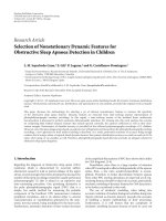
Figure 1: Structure of the color film support.
detection in the Magenta (M) channel of the CYMK color
space, followed by an adaptive restoration in the RGB color
space, according to the visibility of the defect. This strategy
allows us to design a fast and automatic framework that
is sufficiently independent of the knowledge of the various
processes involved in the digitization of the film.
The paper is organized as follows. In Section 2 some
discussions about color scratches are given while Section 3
contains the detection algorithm for BW frames and its
extension to color ones. Section 4 presents the relative
restoration while some experimental results along with
comparisons with the state-of-the-art approaches are then
presented in Section 5. Finally, Section 6 draws the conclu-
sions.
2. COLOR SCRATCHES
Color film is based on the subtractive synthesis, which filters
colors from white light through three separate layers of
sensitive emulsions (see Figure 1). They are, respectively,
sensitive to blue, green, and red. The printed images are then
obtained using the synthesis of yellow, magenta, and cyan.
Accounting for the aforementioned process, it is theoret-
ically possible to guess the color of the scratch according to
the degradation under study. If the mechanism completely
throws away information from the first layer of the frame
support, the only information in the damaged area derives
from magenta and cyan, and then the resulting scratch
is blue. If also the second layer is damaged, the resulting
image is cyan. Finally, if even the third layer is corrupted,
information is completely lost: in this case a white scratch
appears. This case is less frequent and it is the only one where
pure inpainting-based restoration methods are necessary
[15, 16].
Moreover, let Δ
S
be the distance between the slit (scratch
on the film material) and the screen (or lens of the projector).
If λ is the wavelength of the light rays of the lamp while
d
s
is the observed scratch width on the screen, then a well-
known diffraction rule gives the scratch’s width d on the film
material, that is,
d
=
2 Δ
S
λ
d
s
. (1)
Since 0.39 μm
≤ λ ≤ 0.78 μm, the width of the scratch on the
screen for the same slit d depends on the wavelengths that are
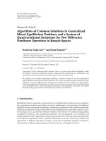
Blue Red Cyan
Figure 2: Degraded frame with three common types of scratch.
From left to right: blue, red, and cyan.
allowed to pass through the slit. It is worth stressing that the
aforementioned classification just considers cases where one
or more than one layer has been completely removed by the
projection mechanism. As a matter of fact, real scratches are
often produced by a partial removal of the film material that
givesthemcolorswithdifferent intensity and pureness.
In order to complete color scratches taxonomy, also red
defects have to be considered. They may be caused in the
very rare case where the mechanism acts on the opposite side
of the support; in this case, it firstly removes the support
and then the cyan layer providing a red scratch. However,
it happens only after a traumatic stress of the film support
that is very unusual. As a matter of fact, red scratches are
mainly caused by the damage of intermediate negatives: if
the yellow and magenta layers have been damaged, the cyan
layer provides a printed image showing a red scratch on
the resulting positive copy. It is evident that in this case,
the diffraction is no longer valid. Nonetheless, it can be
still used for modeling the analyzed defect because of its
simplicity. It entails a sinc
2
behavior for the scratch that
matches enough the real shape of the defect. In fact, scratches
are characterized by a damped oscillating behavior whose
main lobe contains most of the energy (see Section 3 for
details).
Figure 2 shows a degraded frame having (from left to
right) blue, red, and cyan scratches.
3. DETECTION
The main visible property of a line scratch is its geometry: it
is a vertical line with limited width and significant energy.
Therefore, it often represents a peak of the horizontal
projection of the image: the cross-section, as shown in
Figure 3. This latter is the Radon transform of the image
that is computed along the vertical direction and corrected
by its local mean [1, 5, 6]. The vertical extension and the
significant energy in the horizontal cross-section are the main
assumptions in the existing detection algorithms, as briefly
described in the following.
A suitable combination of the Hough transform for
detecting vertical lines and a damped sinusoid model for
Vittoria Bruni et al. 3
2000180016001400120010008006004002000
Column number y
−10
−8
−6
−4
−2
0
2
4
6
8
10
Cross section
Figure 3: Horizontal cross section of the scratched image in
Figure 2. Scratches are indicated by arrows. Their impulsive nature
is evident.
the scratch horizontal projection is effectively exploited in
[1]. The impulsive nature of the scratch is also used in
[4], where it is detected in the vertical detail component
of a wavelet decomposition, assuming a sinc shape for its
horizontal projection. On the contrary, in [9, 10], scratches
are characterized as temporal discontinuities of the degraded
image sequence and then the Kalman filter is used for
their detection. With regard to color scratches, it is worth
mentioning the work in [12]: (intense) blue scratches are
detected as maxima points of the horizontal projection of
a suitable mask. The latter represents the enhanced vertical
lines of the degraded image whose hue, saturation, and value
amplitudes fall into predefined ranges.
The physical formation of a scratch on the film material
has been considered in [5, 6]. It has been proved that the
observed scratch derives from the diffraction effect. In fact,
it is produced by the projector light that passes through the
slit (i.e., the damaged region) of the film material. Therefore,
the scratch appears as an area of partially missing data, where
the original information has not completely been removed,
according to the depth of the slit.
From now on we will, respectively, indicate with (x, y)
the row and column of an image I. Therefore, for an N
1
×N
2
image, 0 ≤ x ≤ N
1
−1and0≤ y ≤ N
2
−1. The contribution
ofascratchoverafixedrow
x of the degraded image I(x, y)
is modelled as follows:
I
x, y
=
1 −(1 −γ)e
(−2/m)|y−c
p
|
G
x, y
+(1− γ)L
x
(y),
(2)
where G(x, y) is the original image andL
x
(y) is the 1D
function model for the scratch, that is,
L
x
(y) = b
p
sinc
2
y − c
p
m
,(3)
according to the diffraction effect. Also, b
p
, c
p
,andm,
respectively, are the maximum brightness, the location
yc
p
+ mc
p
c
p
−m
0
b
p
L
x
(y)
Figure 4: Sinc
2
shape of an ideal scratch on the horizontal cross-
section of the degraded image, as in (3).
(column number), and the horizontal width of the scratch
on the image, as depicted in Figure 4.However,γ is a
normalization parameter that measures the global visibility
of the scratch in the degraded image while e
(−2/m)|y−c
p
|
approximates the positive decay of the scratch contribution
from its central part toward its end. Moreover, γ compares
the average energy of the peaks of the image with the one of
the scratch and it is in the range [0, 1]; hence, the smaller γ,
the more perceptible the scratch.
As (3)andFigure 4 show, the more y far from c
p
, the
less noticeable the scratch, while the significant energy of the
defect is in the range D
= [c
p
−m, c
p
+m]. For that reason, in
(2) the amount of the original information in the degraded
area is weighted by the decay of the scratch contribution and
its degree of visibility over the whole image.
Since scratches are peaks of the horizontal cross-section
of I, as shown in Figure 3, they can be detected among those
peaks that subtend a sinc
2
-like shape, whose width is within a
prefixed range and whose energy is appreciable enough to be
visible in the local context of the analyzed scene. The detailed
detection algorithm is given in Algorithm 1.
Notice that in the step 4(iii), only scratches whose
intensity value over-exceeds the least perceivable one are
selected. Algorithm 1 works for white scratches. For the black
ones, it is necessary to invert the roles of maxima and minima
points at step (2).
3.1. Fast color adaptation
In the detection of color scratches, each single color channel
should be processed in order to detect the corresponding
visible scratches. Nonetheless, this could increase too much
the computational effort of the algorithm. According to the
subtractive mechanism, the CYMK color space has been
analysed and it has been observed that all scratches of the
considered sequences appear in the magenta component as
white lines (see Figure 5). Therefore, this color channel has
been selected for performing a fast detection of the visible
scratches over the whole color image, without specifying the
color of the defect. This component allows in principle to
4 EURASIP Journal on Advances in Signal Processing
(1) Compute the cross section
−→
c of the scratched image I.
(2) For each local maximum c
p
of
−→
c compute:
(i) the distance m from its closest left p
l
and right p
r
adjacent local minima, that is, m =(p
r
− p
l
)/2;
(ii) the mean difference Δ
p
between the corresponding amplitudes, that is,
Δ
p
=
|
−→
c (c
p
) −
−→
c (p
l
)|+ |
−→
c (c
p
) −
−→
c (p
r
)|
2
;
(iii) the area A
p
of the sinc
2
,asin(3), that better approximates
−→
c in the least square sense in the interval [p
l
, p
r
].
(3) Compute the least perceptible intensity value
b
p
for a scratch in the considered image using the Weber’s law, that is,
b
p
=
E
0.98
[6], where E is the average of the energy values Δ
p
used at step 2(ii).
(4) Select the local maxima c
p
such that
(i) m is in the range [3, 12];
(ii) Δ
p
over-exceeds the average value E;
(iii) A
p
over-exceeds the area of the sinc
2
defined in the interval [p
l
, p
r
]withamplitudeb
p
(The sinc
2
is
the one in (3), where b
p
= b
p
).
(5) Store the found maxima locations in the set
−→
C .
Algorithm 1: Algorithm for the detection of black and white scratches.
Let I the RGB degraded image.
(1) Critically subsample the image I by four along the horizontal direction and let I
d
the downsampled image.
(2) Extract the magenta component M (in the CYMK color space) of I
d
.
(3) Apply the detection algorithm for black and white scratches to M.
Algorithm 2: Algorithm for the detection of color scratches.
further reduce false alarms—if compared to a multichannel-
based approach.
From empirical observations, it has been derived that the
width of color scratches is in the range [3, 30] pixels, for
images at resolution 2 K, that is, 1828
×1462 pixels. The range
above is greater than the one used for the BW model [1]
because of the change of resolution. Therefore, the impulsive
nature of the scratch may be penalized, especially in presence
of significant transparency in correspondence to highly
textured areas. In this case, the underlying information may
produce little and spurious peaks in the cross-section that
can alter detection results—see Figure 6(a). To overcome this
problem, a suitable down-sampling can be applied along
the columns direction. Scratches are more impulsive after
this operation and the detection is faster. However, the
sampling operation must reduce the allowed width of the
scratch without destroying its shape. For that reason, the
degraded image has been critically subsampled according to
the Shannon-Whittaker theorem. For the analyzed sequence,
we have empirically found that a good tradeoff is achieved by
critically subsampling by 4—see Figure 6(b).
The detection algorithm, which has been described in
Algorithm 1, is then applied to the critically subsampled
magenta (M)component of the analyzed frame I, as it is
described in Algorithm 2. Such a procedure results appealing
for the involved speed up: just one subsampled channel
(Magenta) has to be processed. The output of the detection
phase consists of the vertical regions of the image that
contain scratches.
4. RESTORATION
Most of the restoration approaches are based on the assump-
tion that regions affected by scratches do not contain original
information [1, 2, 4, 7–9, 11, 15, 16]. Hence, they try to
propagate neighbouring clean information into the degraded
area. The neighboring information can be found in the same
frame [1, 4, 11, 15, 16] or also in the preceding and successive
frame exploiting the temporal coherency, as done in [7–9].
The propagation of information can be performed using
inpainting methods, as in [15, 16], or interpolation schemes
[17]. With regard to this point, different approaches have
been presented. In [1], an autoregressive filter is used for
predicting the original image value within the degraded area.
On the other hand, a cubic interpolation is used in [11],
by also taking into account the texture near the degraded
area (see also [2] for a similar approach), while in [4]
low- and high-frequency components of the degradation are
differently processed. Finally, in [7] each restored pixel is
obtained by a linear regression using the block in the image
that better matches the neighborhood of the degraded pixel.
However, scratches often remove just part of informa-
tion, as it has been argued in Section 3. For that reason, in
[13] an additive multiplicative model is employed. It consists
of a reduction of the image content in the degraded area
till it has the same mean and variance of the surrounding
information. With regard to only blue scratches, in [12]
removal is performed by comparing the scratch contribution
in the blue- and green-color channels with the red one; the
Vittoria Bruni et al. 5
(a) (b) (c)
Figure 5: (a) Magenta component of the image in Figure 2. The three scratches are visible as bright defects. (b), (c) Chroma components
(Cb and Cr, resp.) of the YCbCr color space: the three scratches are differently perceived. In particular, the red scratch is slight in the Cb
component while the blue scratch leaves a black line in the Cr component.
1520150014801460144014201400
Column number y
−3
−2
−1
0
1
2
3
4
Cross section
(a)
390385380375370365360355350
Column number y
−2
−1
0
1
2
3
4
5
6
7
8
Cross section
(b)
Figure 6: (a) Cross-section in the neighborhood of the red scratch in Figure 2 of the original degraded image—the high frequency may alter
detection results since they depend on the local extrema of the signal. (b) Cross-section of the same scratch derived from the original image
critically sampled by four: the shape of the scratch is evident and it is well defined by the model in (3). Notice that the length of the critically
subsampled signal is 1/4 of the full length signal.
assumption is that the contribution of scratches in the red
channel is negligible or completely misses.
Taking into account the model used in the proposed
detection, the degradation can be removed by attenuating
its contribution till it is masked by the original image [5].
The restoration is performed in the wavelet domain using
biorthogonal symmetric filters H, G,
H,
G in an undeci-
mated decomposition. H and G, respectively, are the lowpass
and highpass analysis filters of the subband coding, while
H and
G are the corresponding low- and highpass synthesis
filters. The multiscale decomposition allows to better remove
the scratch from the lowpass component AI(x, y) of the
degraded image. In fact, the shape of the scratch better fits the
data since it becomes more regular. Then, the estimation of
the scratch parameters, such as amplitude and width, is less
sensitive to local high frequencies. In the vertical highpass
component VI(x, y) of the degraded image, the attenuation
corresponds to a reduction of the contrast between the
degraded region and the surrounding information at differ-
ent resolutions, exploiting the semitransparency model. The
attenuation coefficients are derived by inverting the equation
model (2) and by embedding it in a Wiener filter-like scheme,
where the noise is the scratch, that is,
w
x, y
=
AI
x, y
−
C
2
AL
x
(y)
2
AI
x, y
−
C
2
AL
x
(y)
2
+
C
2
/C
1
AL
x
(y)
2
∀ y ∈ D,
(4)
6 EURASIP Journal on Advances in Signal Processing
Let
−→
C the set of detected scratches. For each element c
p
∈
−→
C :
(1) select the color component (among R, G, B) whose cross section has the highest value in correspondence to
c
p
;
(2) adapt the scratch position to the full image dimension, that is, c
p
= 4c
p
;
(3) compute the undecimated wavelet decomposition of the selected component up to J
= log
2
(m/s
H
)
scale level, where s
H
is the support length of the low pass filter associated to the employed wavelets basis and m
is the estimated scratch width. Let
{A
J
, {V
j
}
1≤j≤J
} respectively be the low and high pass sub-bands of the
decomposition;
(4) apply the restoration algorithm to each sub-band of the decomposition as follows:
for each row
x
(a) estimate the amplitude b
p
in the least squares sense of the scratch shape at the considered band using (5)
and the scratch domain at the coarsest resolution J,thatis,D
= [c
p
−2
(J−1)
m, c
p
+2
(J−1)
m];
(b) compute the filter coefficients w(
x, y), ∀y ∈ D as defined in (4), suitably adapted to the considered sub-band;
(c) apply w(
x, y) to the analyzed row:
V
j
x, y
=
w
x, y
V
j
x, y
vertical details
A
J
x, y
=
w
x, y
A
J
x, y
−
M
A
+ M
A
low pass band,
where M
A
is the local average of the low pass sub-band A
J
(x, y) in the horizontal neighborhood Ω of
the scratch domain D,thatis,y
∈ Ω = [c
p
−2
(J−1)
m −s
H
, c
p
+2
(J−1)
m + s
H
].
Invert the wavelet decomposition using the restored bands and let
I be the resulting partially restored image;
(5) extract the luminance component of
I and evaluate the energy value in correspondence to c
p
in the cross
section of this component, as done at step 2(iii) of the detection algorithm. Compare it with the least admissible
energy for a visible scratch, as in steps (3) and 4(iii) of the detection algorithm.
If the scratch is still visible, go to step (1) and apply the algorithm to the remaining color channels; else stop.
Algorithm 3: Restoration.
Figure 7: Restored frame in Figure 2 using the proposed algorithm.
where AL
x
(y) is the lowpass component of the function in
(3), C
1
= (1 − (1 − γ)e
(−2/m)|y−c
p
|
), C
2
= (1 − γ), and D is
the scratch domain. Notice that C
1
and C
2
are derived from
(2). Moreover, (4) can be simply adapted to the vertical detail
bands if VI and VL
x
are considered instead of AI and AL
x
.
The shrinkage coefficients w(
x, y) measure a sort of signal-
to-noise ratio, so that the scratch contribution is attenuated
according to its local contrast with respect to the original
information. In order to make this measure more precise, the
algorithm is adapted at each row of the analyzed subband. In
fact, the location of the scratch could slightly change from
a row to another one, while the detection parameters, such
as the amplitude b
p
and the location c
p
, are influenced by
the down-sampling. Therefore, the algorithm firstly corrects
the global detection parameters, that is, location of the
maximum, width, asymmetry (resp., indicated by b
p
, c
p
, m)
according to the local information. In particular, b
p
can be
estimated from the data, minimizing the mean-square error
in the scratch domain D
= [c
p
−m, c
p
+ m], that is,
b
p
= min
α∈R
y∈D
AI
x, y
−αAS
x
(y)
2
,(5)
where AS
x
(y) = sinc
2
(|y − c
p
|/m)∗H is the function model
for the lowpass component of a sinc
2
shape. Sob
p
is then the
peak value of the sinc
2
function that better matches, in the
least-square sense, with the data at the considered resolution.
The perception of the defect can also be used to establish
the order of the restoration of the three color channels. In
fact, the removal of the defect in color images is usually
performed in each color channel (R, G, B) independently.
In order to minimize the computational effort and to
avoid color artifacts, scratch removal can be performed
in a hierarchical way: from the channel where scratch
has the main contribution (the highest energy) to the
one where it is less visible. The removal of the scratch
from the first channel is followed by a visibility check on
the luminance component, using the perception measures
(based on Weber’s law) of the detection step. More precisely,
the energy of the scratch in the degraded region is compared
with the minimum energy allowed for a visible object in
the luminance component. If it is still visible, that is, the
energy over-exceeds the threshold value, then the restoration
algorithm on the successive channel is applied. Otherwise,
the restoration process for the analyzed scratch stops. In this
way, if the contribution of a scratch in a color channel is
negligible for the human perception, any restoration process
is performed.
Vittoria Bruni et al. 7
(a) (b)
(c) (d)
Figure 8: Zoom of the red scratch in Figure 2(a) restored using the proposed algorithm (b), the method in [1] (c) and the method in [7]
(d).
4.1. The algorithm
In Algorithm 3, a general sketch of the whole restoration
algorithm is given.
5. EXPERIMENTAL RESULTS
The algorithm has been tested on several real sequences
(digitized copies of actual damaged films) having different
subjects and of 1-2 minutes length (1500–3000 frames).
In this paper we have shown some results concerning the
sequences extracted from the film Io sono un autarchico
(1976), kindly provided by Sacher Film s.r.l In order to
check the visual quality of the results, some of the digital
restored sequences have been copied back on film.
The detection algorithm has been performed on the
cross-section of the magenta component of the image
critically subsampled by 4. All scratches in the analyzed
frames are selected with a few (or without) false alarms.
The undecimated wavelet transform using the biorthog-
onal 5/3 Le Gall filter has been used in the restoration
algorithm, while the scale level depends on the width m of the
scratch. In particular, it is log
2
(m/s
H
), where m is estimated
in the detection step and s
H
is the support of the lowpass
analysis filter associated to the adopted wavelet basis. LeGall
wavelets (5/3) are employed since they are symmetric and the
support length of their analysis filters well matches with the
admissible width for a scratch.
As it can be observed in Figure 7, the visual quality of
the restored image is satisfying. In fact, scratches are removed
without introducing artifacts both in the image content and,
especially, in color information (some results are available at
/>∼vitulano/ext model.htm).
The proposed framework has been compared with the
algorithms in [1, 12] since they deal with one frame at a time.
This cannot be considered a restriction. In fact, the initial
condition of temporal detectors is the output of a spatial
detector, as in [3, 7]. In particular, it is worth mentioning
that the visibility-based detector in [6] has been employed in
[7] since its competitive detection performances and for its
ability in false alarms rejection.
For the analyzed sequences, we notice that the method in
[1] fails in the detection of slight scratches while the one in
[12] only works for very intense blue scratches, as the one in
the leftmost part of the image in Figure 2.
Figure 8 shows the restoration results in correspondence
to the red scratch: the texture of the carpet is preserved by the
proposed algorithm while smoothing is introduced by the
algorithms in [1, 7]. This is possible thanks to the adaptivity
of the attenuation filter in (4) to the local image content,
inside and outside the degraded region, even in presence of
a diagonal edge. In fact, the algorithm works row by row.
It separately processes the low and the high frequency of
the degraded region, exploiting the physical model of the
defect. It is worth stressing that the red scratch is wider than
the classical black and white ones and it seems to lose the
8 EURASIP Journal on Advances in Signal Processing
(a) (b)
(c) (d)
Figure 9: Zoom of the blue scratch in Figure 2(a) restored using the proposed algorithm (b), the method in [12] (c), and the method in [7]
(d).
impulsive nature. For that reason, the approaches in [1, 7]
create a blurred restored image.
The proposed approach does not introduce false colors,
as it can be observed in the restoration of a blue scratch in
Figure 9. The better performance of the proposed algorithm,
in this case, is due to the fact that also the red component is
restored. In fact, this scratch has a visible contribution on this
component that is neglected by the approach in [12]. It is also
worth noticing that the two thin dark lines near the scratch
are not present in the image restored using the proposed
model, thanks to a precise detection (three scratches are
detected instead of a single one).
With regard to the computational effort, it is lower
than most of the state-of-the-art techniques. In fact, as
the approach in [12], the algorithm uses simple and fast
computations, while it avoids expensive operations like the
pixel-wise search of the best coherent block employed in [7],
or correlation matrices, as in [1]. For a scratch occupying all
the vertical extension of a 2 K frame (1828
×1462 pixels), the
restoration algorithm requires 2 seconds on a machine with
a 2 GHz processor and a 1 G Ram, in a nonoptimized Matlab
code.
Finally, the algorithm does not require any user’s interac-
tion since it is able to adapt both detection and restoration
phases to the analyzed image.
6. CONCLUSIONS
In this paper a unified model for detection and restoration
of line scratches on color movies has been presented. The
model considers light diffraction and human perception
to guide the reduction of the defect contribution in the
image till it is masked by the local context. The resulting
framework improves the performances of the available
restoration approaches requiring a low computational effort.
Future research will be oriented to deal with more critical
cases, such as scratches on highly textured areas or heavily
degraded images. Moreover, efficient methods for false-
alarms rejection will also be investigated.
ACKNOWLEDGMENTS
This paper has been partially supported by the FIRB
project no. RBNE039LLC, “A knowledge-based model for
digital restoration and enhancement of images concerning
archaeological and monumental heritage of the Mediter-
ranean coast.” Authors would like to thank Sacher Film s.r.l.
for providing the frames used in this paper, and Franco
Strappini and Mario Musumeci of Centro Sperimentale di
Cinematografia, Cineteca Nazionale (Rome) for their helpful
suggestions and insightful comments.
REFERENCES
[1] A.C.Kokaram,Motion Picture Restoration: Digital Algorithms
for Artefact Suppression in Degraded Motion Picture Film and
Video, Springer, Berlin, Germany, 1998.
[2] L. Rosenthaler and R. Gschwind, “Restoration of movie films
by digital image processing,” in Proceedings of IEE Seminar on
Dig ital Restoration of Film and Video Archives, pp. 6/1–6/5,
London, UK, January 2001.
[3] B. Besserer and C. Thir
´
e, “Detection and tracking scheme for
line scratch removal in an image sequence,” in Proceedings of
the 8th European Conference on Computer Vision (ECCV ’04),
vol. 3023 of Lecture Notes in Computer Science, pp. 264–275,
Prague, Czech Republic, May 2004.
[4] T. Bretschneider, O. Kao, and P. J. Bones, “Removal of
vertical scratches in digitised historical film sequences using
wavelet decomposition,” in Proceedings of the Image and Vision
Computing New Zealand (IVCNZ ’00), pp. 38–43, Hamilton,
New Zealand, November 2000.
Vittoria Bruni et al. 9
[5] V. Bruni, D. Vitulano, and A. Kokaram, “Fast removal of
line scratches in old movies,” in Proceedings of the 17th
International Conference on Pattern Recognition (ICPR ’04),
vol. 4, pp. 827–830, Cambridge, UK, August 2004.
[6] V. Bruni and D. Vitulano, “A generalized model for scratch
detection,” IEEE Transactions on Image Processing, vol. 13, no.
1, pp. 44–50, 2004.
[7] M. K. Gulu, O. Urhan, and S. Erturk, “Scratch detection via
temporal coherency analysis and removal using edge priority
based interpolation,” in Proceedings of IEEE International
Symposium on Circuits and Systems (ISCAS ’06), pp. 4591–
4594, Kos Island, Greece, May 2006.
[8] M. Haindl and J. Filip, “Fast restoration of colour movie
scratches,” in Proceedings of the 16th International Conference
on Pattern Recognition (ICPR ’02), vol. 3, pp. 269–272, Quebec,
Canada, August 2002.
[9] L. Joyeux, S. Boukir, and B. Besserer, “Film line scratch
removal using Kalman filtering and Bayesian restoration,”
in Proceedings of the 5th IEEE Workshop on Applications of
Computer Vision (WACV ’00), pp. 8–13, Palm Springs, Calif,
USA, December 2000.
[10] L. Joyeux, O. Buisson, B. Besserer, and S. Boukir, “Detection
and removal of line scratches in motion picture films,” in
Proceedings of IEEE Computer Society Conference on Computer
Vision and Pattern Recognition (CVPR ’99), vol. 1, p. 553, Fort
Collins, Colo, USA, June 1999.
[11] G. Laccetti, L. Maddalena, and A. Petrosino, “Paral-
lel/distributed film line scratch restoration by fusion tech-
niques,” in Proceedings of the International Conference on
Computational Science and Its Applications (ICCSA ’04), vol.
3044 of Lecture Notes in Computer Science, pp. 525–535, Assisi,
Italy, May 2004.
[12] L. Maddalena and A. Petrosino, “Restoration of blue scratches
in digital image sequences,” Tech. Rep. 21, ICAR-NA, Napoli,
Italy, December 2005.
[13] L. Tenze and G. Ramponi, “Line scratch removal in vintage
film based on an additive/multiplicative model,” in Proceedings
of IEEE-EURASIP Workshop on Nonlinear Signal and Image
Processing (NSIP ’03), Grado, Italy, June 2003.
[14] S. Winkler, Digital Video Quality: Vision Models and Metrics,
John Wiley & Sons, New York, NY, USA, 2005.
[15] M. Bertalmio, G. Sapiro, V. Caselles, and C. Ballester,
“Image inpainting,” in Proceedings of the 27th International
Conference on Computer Graphics and Interactive Techniques
(SIGGRAPH ’00), pp. 417–424, New Orleans, La, USA, July
2000.
[16] S. Esedoglu and J. Shen, “Digital inpainting based on the
Mumford-Shah-Euler image model,” European Journal of
Applied Mathematics, vol. 13, no. 4, pp. 353–370, 2002.
[17] D. Kincaid and W. Cheney, Numerical Analysis, Brooks Cole,
Florence, Ky, USA, 2002.