Báo cáo hóa học: " Research Article Comparison of Semidistributed Multinode TOA-DOA Fusion Localization and GPS-Aided TOA (DOA) Fusion Localization for MANETs" pot
Bạn đang xem bản rút gọn của tài liệu. Xem và tải ngay bản đầy đủ của tài liệu tại đây (1.17 MB, 16 trang )
Hindawi Publishing Corporation
EURASIP Journal on Advances in Signal Processing
Volume 2008, Article ID 439523, 16 pages
doi:10.1155/2008/439523
Research Article
Comparison of Semidistributed Multinode TOA-DOA
Fusion Localization and GPS-Aided TOA (DOA) Fusion
Localization for MANETs
Zhonghai Wang and Seyed Zekavat
Department of Electrical and Computer Engineering, College of Engineering, Michigan Technological University,
Houghton, MI 49931, USA
Correspondence should be addressed to Zhonghai Wang,
Received 20 February 2008; Revised 30 July 2008; Accepted 6 October 2008
Recommended by Fredrik Gustafsson
This paper evaluates the performance of a semidistributed multinode time-of-arrival (TOA) and direction-of-arrival (DOA) fusion
localization technique in terms of localization circular error probability (CEP). The localization technique is applicable in mobile
ad hoc networks (MANETs) when global positioning system (GPS) is not available (GPS denied environments). The localization
CEP of the technique is derived theoretically and verified via simulations. In addition, we theoretically derive the localization CEP
of GPS-aided TOA fusion and GPS-aided DOA fusion techniques, which are also applicable in MANETs. Finally, we compare
these three localization techniques theoretically and via simulations. The comparison confirms that in moderate scale MANETs,
the multinode TOA-DOA fusion localization technique achieves the best performance; while in large scale MANETs, GPS-aided
TOA fusion leads to the best performance.
Copyright © 2008 Z. Wang and S. Zekavat. This is an open access article distributed under the Creative Commons Attribution
License, which permits unrestricted use, distribution, and reproduction in any medium, provided the original work is properly
cited.
1. INTRODUCTION
Node localization is required in ad hoc networks to support
resource allocation [1], routing [2, 3], situation awareness [4,
5], and so forth. Many coarse and fine localization techniques
applicable in ad hoc networks have been introduced in the
literature. Coarse localization techniques that depend on
power measurement include node connectivity fusion [6–8],
and received signal strength indication (RSSI) [9, 10]. The
proposed techniques in [6, 7] assume static base-nodes, while
the approach proposed in [8] considers node mobility. Fine
localization techniques that depend on TOA and/or DOA
estimation include fusion of GPS (global positioning system)
and communication [11, 12], time-of-arrival (TOA) or time-
difference-of-arrival (TDOA) fusion [13–16], direction-of-
arrival (DOA) fusion [17–19], TOA-DOA joint estimation
[20], centralized multinode TOA-DOA fusion [21], and
hybrid positioning techniques [22–24]. Please note that
when constraint is available, such as geometric constraint
[19], a part of errors (especially those large errors) are
detected and removed in data processing; hence, higher
performance could be achieved.
In this paper, we define base-nodes as nodes capable of
TOA and/or DOA estimation. In other words, base-nodes are
capable of estimating the position of other nodes located in
their coverage area. In addition, target-nodes are those nodes
whose positions are estimated by the base-nodes.
In mobile ad hoc networks (MANETs), all nodes are
moving. Accordingly, the environment and the position of
base-nodes are changing. As a result, techniques such as
node connectivity fusion and RSSI that require fixed base-
nodes’ position and fixed environment are not applicable.
In these situations, if GPS can be used to determine base-
nodes’ position, the techniques requiring known base-nodes’
position are capable of positioning. Examples are fusion of
GPS and communication, GPS-aided TOA fusion [25], and
GPS-aided DOA fusion [26]. In many applications, GPS
signal is not available. In this case, techniques that function
independent of GPS should be implemented. Examples
of GPS-independent localization techniques are TOA-DOA
2 EURASIP Journal on Advances in Signal Processing
joint estimation, centralized and semidistributed multin-
ode TOA-DOA fusion localization schemes. The proposed
semidistributed approach is opposed to the centralized
scheme. In the centralized scheme, only one base-node is in
charge of data processing (fusion) to localize all target-nodes.
Thus, that base-node needs a very high processing power.
In the proposed semidistributed scheme, taking into account
the geometrical distribution, each base-node undertakes the
data processing (fusion) to localize some target-nodes (so it
is called “semi”) in its coverage area. Here, the processing
power would be distributed across base-nodes. Thus, the
processing power assigned to each base-node would be lower.
The centralized and semidistributed multinode TOA-
DOA fusion localization techniques take the advantage of
base-nodes’ property, capable of estimating other nodes
position independently. The reference and nonreference
base-nodes localize each other and fuse the localization
information to improve base-nodes’ position estimation
accuracy. Then, they cooperate to estimate target-nodes’
position. The target-nodes’ position is achieved via data
fusion across multiple base-nodes.
In centralized multinode TOA-DOA fusion, the data
processing is entirely accomplished in the reference base-
node; while in the semidistributed fusion technique, the
data processing is distributed across multiple base-nodes. In
addition, in the semidistributed scheme, the reference base-
node is selected via a suboptimal method that minimizes the
average positioning error. If the two localization methods
apply the same reference base-node selection scheme, their
localization accuracy would be equal.
TOA fusion and TDOA fusion performance is the
same [27]; hence, we only consider the performance of
GPS-aided TOA fusion. In GPS-aided TOA (DOA) fusion
scheme, GPS receivers are applied to estimate base-nodes’
position. Then target-node’s TOAs (DOAs) estimated by
multiple base-nodes, and, base-nodes’ positions are fused
to estimate the target-node position. In these techniques,
GPS positioning error can be transformed to TOA (DOA)
estimation error, and it equivalently increases the target-
node positioning error. The TOA estimation error generated
by GPS positioning error is independent of the distance
between target node and base-node; but the DOA estimation
error generated by GPS positioning error is a function of the
distance between target-node and base-node. If target-node
is far from base-node, the DOA estimation error generated by
GPS positioning error is negligible. However, if target-node
is close to base-node, the DOA estimation error generated by
GPS positioning error is considerable.
In semidistributed multinode TOA-DOA fusion local-
ization, TOA and DOA are estimated at base-nodes by
processing signals transmitted by base-nodes or target-
nodes. If line-of-sight (LOS) is available, then a good
performance can be achieved. In GPS-aided TOA (DOA)
fusion, GPS positioning information and target-node TOA
(DOA) information must be computed at base-nodes. The
sources of positioning error in these systems include the lack
of availability of the LOS between the transmitter and the
receiver as well as reflection effects (e.g., in the downtown
areas) that reduces the positioning accuracy of the GPS.
In the proposed semidistributed technique and GPS-
aided DOA fusion, major errors (a complete confusion)
may occur if the LOS signal between the base-nodes and
target-nodes is blocked. GPS-aided TOA (DOA) fusion
requires LOS to both GPS satellites and target-node; while
the semidistributed method needs LOS between base-nodes
and base-nodes to target-node. Hence, when signals to GPS
satellites are blocked, the semidistributed multinode TOA-
DOA fusion may perform.
Because nodes are moving, the base-nodes positions and
target-nodes TOA and/or DOA used in the fusion to localize
target-nodes are not computed simultaneously. Here, we
assumed a similar system as the wireless local positioning
system (WLPS) discussed in [20]. WLPS enables a base-node
to localize target-nodes periodically: the base-nodes transmit
periodic signals with a period that is called identification
request repetition time (IRT) and target-nodes automatically
respond to those signals. One IRT is assigned to estimate
base-nodes position and another IRT is assigned to estimate
target-nodes TOA and DOA; hence, the time difference
between base-node position estimation and target-nodes
TOA and DOA estimation is about IRT. Assuming IRT
= 24
milliseconds, a node with a speed of 10 m/s (outdoor) would
move 0.24 meters within this time period. This error is
generated by nodes movement and would be tolerable in
outdoor application.
GPS positioning updating rate is limited to 20 Hz. This
limits the GPS-based positioning updating rate. Higher
updating rate would involve with some error, if the nodes
mobility increases. If the system positioning updating rate
is 20 Hz and base-nodes TOA/DOA estimation are synchro-
nized with GPS, then there would be no time difference
between the base-node position estimation and target-nodes
TOA (DOA) estimation. This removes the latency across
these two estimations and reduces their associated errors. In
this work, we assume full synchronization.
Different localization performance evaluation standards
have been introduced. These standards include cumulative
localization error distribution [6], mean and standard
deviation of the positioning error [9], normalized mean
square of the positioning error [21], and geometrical dilution
of precision (GDOP) [14, 28, 29]. GDOP only provides
the positioning performance of a system considering single
category of measurement (TOA or DOA) and assuming
the measurement errors are independent and identically
distributed. Normalized mean square, mean and standard
deviation of the positioning error can be applied to any
positioning system, but it only provides one statistics of
the positioning performance. Cumulative localization error
distribution, also known as circular error probability (CEP)
[30], incorporates the cumulative density function (CDF) of
the positioning error. Hence, it includes more information
on the statistics of the positioning error. In addition, it
can be applied to any positioning system in any scenario.
Accordingly, in this paper, we evaluate the performance of
the semidistributed multinode TOA-DOA fusion localization
technique in terms of localization CEP in the condition of
all target-nodes being localized; then, we compare it to that
of GPS-aided TOA (DOA) fusion. In the condition of not
Z. Wang and S. Zekavat 3
all target-nodes being localized, we use the probability of
target-nodes being localized as standard to compare the three
localization methods.
The rest of the paper is organized as follows. Section 2
reviews the semidistributed multinode TOA-DOA fusion
localization scheme. Section 3 derives the localization CEP of
the semidistributed multinode TOA-DOA fusion. Section 4
studies the impact of GPS positioning error on TOA (DOA)
estimation and derives the localization CEP of these two
methods. Section 5 presents simulation results, comparison
of the introduced techniques and discussions. Section 6
concludes the paper.
2. SEMIDISTRIBUTED MULTINODE TOA-DOA
FUSION LOCALIZATION TECHNIQUE
Here, we briefly review the semidistributed multinode TOA-
DOA fusion localization technique.
2.1. MANET structure and assumptions
Here, we assume the MANET that apply semidistributed
multinode TOA-DOA fusion localization are composed of
two categories nodes: (i) base-nodes equipped with antenna
arrays that are capable of estimating the TOA and DOA
of target-nodes or other base-nodes; and, (ii) target-nodes
equipped with omnidirectional antennas that respond to
the inquiring signal transmitted by base-nodes. Here, base-
nodes transmit a signal periodically that requests all target-
nodes in its coverage area to announce their availability
by sending a signal back to the base-node automatically.
The base-node calculates the TOA of the received signal
compared to the transmitted one in order to calculate the
range (see [20]).
Thus, base-nodes and target-nodes communicate. This
communication can be incorporated to transmit other infor-
mation. For example, if some sensors are installed at target-
nodes, the corresponding information can be communicated
with base-nodes and vice versa. Hence, the proposed system
may also support the process of communication within an ad
hoc sensor network.
In addition, antenna arrays installed at the receiver
of base-nodes estimate the DOA. Combining DOA and
TOA, each base-node would be able to localize the target-
nodes in its coverage area independently. Different TOA and
DOA estimation techniques and their corresponding error
analysis for antenna arrays have been discussed in [31–33].
Direct sequence code division multiple access (DS-CDMA)
is applied to maintain orthogonality across the signals
transmitted by each node and to improve the performance.
The MANET structure is shown in Figure 1.Here,we
assume that the following hold. (1) There are n base-nodes
and m target-nodes (usually n
m) in the MANET (to
compare multinode TOA-DOA fusion localization technique
with GPS-aided TOA (DOA) fusion, we set n
≥ 3). (2)
All nodes in the system are uniformly distributed in the
MANET. (3) Every base-node localizes target-nodes located
in its coverage area (radius is R
max
), and the MANET
coverage radius is αR
max
. The multinode TOA-DOA fusion
y
2
2
1
1
n
m
j
θ
(B)
31
3
R
(T)
1j
/θ
(T)
1j
R
(T)
ij
/θ
(T)
ij
θ
(B)
13
x
R
(B)
1i
/θ
(B)
1i
R
(B)
i1
/θ
(B)
i1
i
3
Base-node
Target-node
Figure 1: The structure of the MANET that applies semidistributed
multinode TOA-DOA fusion.
and its localization CEP are derived in the condition of
0 <α
≤ 0.5 (i.e., all base-nodes localize all target-nodes
in the MANET). A simple geometry can justify that if the
MANET coverage area radius is more than 0.5R
max
,some
base-nodes might not be able to localize all target-nodes
in the MANET. The short coming of the semidistributed
multinode TOA-DOA fusion in the condition of 0.5 <αis
discussed in Section 2.4. (4) One base-node (e.g., base-node
1) is carefully selected as the reference base-node, whose local
coordinates are considered as the main coordinates, in which
all nodes are localized. (5) TOA (range) estimation errors are
independent zero mean Gaussian random variables with the
same variance σ
2
TOA
(σ
2
R
), and DOA estimation errors are also
independent zero mean Gaussian random variables with the
same variance σ
2
θ
. (6) Both range and angle estimation errors
are small (when we calculate the positioning error using
linearization technique, higher order terms can be ignored);
(7) DOA angle is measured anticlockwise with respect to
the x-axis (e.g., east); and, (8) all base-nodes simultaneously
localize target-nodes.
2.2. Localization scheme
The localization scheme includes three main stages.
(1) The reference base-node selection and cluster forma-
tion: a base-node is selected as the reference base-
node to achieve optimal performance, and all nodes
are localized in the reference base-node’s coordinate.
A suboptimal scheme is used to select the reference
base-node to decrease the computational and time
costs (see Appendix A). Clusters are formed to
enhance the positioning updating rate. Each cluster
consists of one base-node and multiple target-nodes.
The base-node is in charge of target-nodes’ position
estimation data fusion in that cluster. The clustering
4 EURASIP Journal on Advances in Signal Processing
scheme uniformly distributes all target-nodes across
all clusters. Note that all nodes in the MANET are
dynamic. Hence, the reference base-node selection
and cluster formation would be performed periodi-
cally to maintain the positioning accuracy. Based on
(11)and(12) below and the relevant explanations,
the accuracy is independent of clustering. In the
following discussion, we assume base-node 1 is the
reference base-node.
(2) Nonreference base-nodes position estimation: any pair
of nonreference base-node (base-node i, i
∈{2, ,
n
}) and the reference base-node (base-node 1), that
is, (i, 1), localize each other. Then, the localization
information is fused at the nonreference base-node
to estimate the nonreference base-node position.
Accordingly, all nonreference base-nodes would find
their position with respect to the reference base-
node. Then, nonreference base-nodes broadcast their
position. Hence, each base-node knows all base-
nodes’ position.
(3) Target-nodes position estimation: there are four steps
in this stage: (a) base-nodes find the position of
target-nodes in their coverage area, for example,
in Figure 1,base-nodes1ton localize target-nodes
1tom. Note that in Figure 1 base-node 3 is in
charge of the data fusion of target-node j, and, base-
node 1 is in charge of the data fusion of target-
node 1; (b) base-nodes broadcast the target-node
position information; (c) only the base-node in
charge of the data fusion of a target-node receives
the broadcasted target-node position, for example,
only base-node 3 receives the broadcasted position
information of target-node j; (d) the base-node in
charge of the target-node’s position estimation data
fusion fuses the position information of that target-
node provided by multiple base-nodes to localize the
target-node.
2.3. Multinode TOA-DOA fusion
Comparing to the centralized scheme, the semidistributed
method improves the positioning updating rate and reduces
the requirement for the reference base-node. The data
fusion technique in the two methods is the same; in the
semidistributed method, multiple base-nodes are in charge
of data fusion; while in the centralized scheme, the data
fusion is accomplished only by the reference base-node. The
associated fusion equations are derived in [21]. Here, we only
review the equations required in this paper.
2.3.1. Nonreference base-nodes position estimation fusion
The reference base-node (base-node 1) estimates nonref-
erence base-node i’s (i
/
=1) position as (R
(B)
1i
, θ
(B)
1i
)and
nonreference base-node i estimates the reference base-
node position as (R
(B)
i1
, θ
(B)
i1
). The base-node i’s position is
estimated as (
R
(B)
1i
,
θ
(B)
1i
) via fusing (R
(B)
1i
, θ
(B)
1i
)and(R
(B)
i1
, θ
(B)
i1
)
using weighted sum. The fusion objective function is the
minimization of the mean square of the base-node i ’s
positioning circular error, which is the distance between the
real node position and the estimated one. By minimizing the
mean square of the positioning circular error, the fused base-
node i’s position in the main polar coordinates is calculated
[21]
R
(B)
1i
=
R
(B)
1i
+ R
(B)
i1
2
,
θ
(B)
1i
=
⎧
⎪
⎪
⎪
⎪
⎨
⎪
⎪
⎪
⎪
⎩
θ
(B)
1i
+ θ
(B)
i1
−π
2
, θ
(B)
1i
<π,
θ
(B)
1i
+ θ
(B)
i1
+ π
2
, θ
(B)
1i
≥ π.
(1)
In the main rectangular coordinates, the base-node i’s
position (x
(B,t)
1i
, y
(B,t)
1i
) corresponds to
x
(B,t)
1i
= x
(B)
1i
+ Δx
(B)
1i
=
R
(B)
1i
+ Δ
R
(B)
1i
·cos
θ
(B)
1i
+ Δ
θ
(B)
1i
,
y
(B,t)
1i
= y
(B)
1i
+ Δy
(B)
1i
=
R
(B)
1i
+ Δ
R
(B)
1i
·
sin
θ
(B)
1i
+ Δ
θ
(B)
1i
.
(2)
In (2), Δ
R
(B)
1i
(Δ
θ
(B)
1i
) is the fused range (angle) estimation
error, (
x
(B)
1i
, y
(B)
1i
) is the estimated base-node i’s position by
fusion. The positioning error (Δ
x
(B)
1i
, Δy
(B)
1i
) corresponds to
Δ
x
(B)
1i
= Δ
R
(B)
1i
cos
θ
(B)
1i
−Δ
θ
(B)
1i
·
R
(B)
1i
sin
θ
(B)
1i
,
Δ
y
(B)
1i
= Δ
R
(B)
1i
sin
θ
(B)
1i
+ Δ
θ
(B)
1i
·
R
(B)
1i
cos
θ
(B)
1i
.
(3)
Please note that the positioning error is achieved by
expanding (2) using Taylor series and ignoring higher order
terms. Range error (Δ
R
(B)
1i
)andangleerror(Δ
θ
(B)
1i
) are two
independent zero mean Gaussian random variables; hence,
they are jointly Gaussian. Accordingly, Δ
x
(B)
1i
and Δy
(B)
1i
are jointly Gaussian random variables. The corresponding
positioning variances in the main rectangular coordinates are
[21]
σ
2
x
(B)
1i
=
σ
2
R
cos
2
θ
(B,t)
1i
2
+
σ
2
θ
(R
(B,t)
1i
)
2
sin
2
θ
(B,t)
1i
2
,
σ
2
y
(B)
1i
=
σ
2
R
sin
2
θ
(B,t)
1i
2
+
σ
2
θ
(R
(B,t)
1i
)
2
cos
2
θ
(B,t)
1i
2
.
(4)
Here, (R
(B,t)
1i
, θ
(B,t)
1i
) is the base-node i’s true position in
the main polar coordinates. So far, we have completed
computing nonreference base-nodes’ position in the main
rectangular coordinates and the corresponding positioning
variances.
2.3.2. Target-nodes position estimation fusion
Base-node i estimates target-node j’s position as (
x
(T)
ij
, y
(T)
ij
)
in its own rectangular coordinates, which corresponds to
x
(T)
ij
= R
(T)
ij
cos θ
(T)
ij
, y
(T)
ij
= R
(T)
ij
sin θ
(T)
ij
. (5)
Z. Wang and S. Zekavat 5
Here, (R
(T)
ij
, θ
(T)
ij
) is the target-node j’s position in base-node
i’s local polar coordinates estimated by base-node i.The
corresponding positioning error is
Δ
x
(T)
ij
= ΔR
(T)
ij
cos θ
(T)
ij
−Δθ
(T)
ij
·R
(T)
ij
sin θ
(T)
ij
,
Δ
y
(T)
ij
= ΔR
(T)
ij
sin θ
(T)
ij
+ Δθ
(T)
ij
·R
(T)
ij
cos θ
(T)
ij
.
(6)
Similar to the explanation on (3), in (6), Δ
x
(T)
ij
and Δy
(T)
ij
are jointly Gaussian and the corresponding variances are σ
2
x
(T)
ij
and σ
2
y
(T)
ij
. Because range and angle estimation errors (ΔR
(T)
ij
and Δθ
(T)
ij
) are independent and zero mean, using (6), it can
be shown that
σ
2
x
(T)
ij
= E
Δx
(T)
ij
2
=
σ
2
R
cos
2
θ
(T,t)
ij
+ σ
2
θ
R
(T,t)
ij
2
sin
2
θ
(T,t)
ij
,
σ
2
y
(T)
ij
= E
Δy
(T)
ij
2
=
σ
2
R
sin
2
θ
(T,t)
ij
+ σ
2
θ
R
(T,t)
ij
2
cos
2
θ
(T,t)
ij
.
(7)
In (7), (R
(T,t)
ij
, θ
(T,t)
ij
) is the target-node j’s true position in
the base-node i’s local polar coordinates. When we transform
target-node j’s position (
x
(T)
ij
, y
(T)
ij
) into the main rectangular
coordinates, we achieve (
x
(T)
1ij
, y
(T)
1ij
)
x
(T)
1ij
= x
(B)
1i
+ x
(T)
ij
, y
(T)
1ij
= y
(B)
1i
+ y
(T)
ij
. (8)
The error (Δ
x
(T)
1ij
, Δy
(T)
1ij
) and error variance (σ
2
x
(T)
1ij
, σ
2
y
(T)
1ij
)in
the main coordinates, respectively, correspond to
Δ
x
(T)
1ij
=Δx
(B)
1i
+Δx
(T)
ij
, Δy
(T)
1ij
=Δy
(B)
1i
+Δy
(T)
ij
,
(9)
σ
2
x
(T)
1ij
= σ
2
x
(B)
1i
+ σ
2
x
(T)
ij
, σ
2
y
(T)
1ij
= σ
2
y
(B)
1i
+ σ
2
y
(T)
ij
.
(10)
The target-node j’s position estimation fusion is imple-
mented via weighted sum across multiple base-nodes
x
(T)
j
=
n
i=1
p
ij
x
(T)
1ij
, y
(T)
j
=
n
i=1
q
ij
y
(T)
1ij
. (11)
Here, p
ij
and q
ij
, i = 1, 2, , n, are fusion weights for
target-node j’s x and y coordinates, respectively. Based on
(11), in the target-node localization fusion process, the ref-
erence base-node provides one-hop positioning information
and nonreference base-nodes provide two-hop positioning
information. In the fusion, the weight of one-hop position-
ing (p
1j
) is larger than that of the two-hop positioning.
Accordingly, involving the reference base-node reduces the
target-nodes positioning error in the reference base-node
coordinates.
The estimation error via the fusion corresponds to
Δ
x
(T)
j
=
n
i=1
p
ij
·Δx
(T)
1ij
, Δy
(T)
j
=
n
i=1
q
ij
·Δy
(T)
1ij
. (12)
Now, because, as explained for (3)and(6), Δ
x
(T)
1ij
and Δy
(T)
1ij
are jointly Gaussian random variables, their linear combina-
tions that are Δ
x
(T)
j
and Δy
(T)
j
would be jointly Gaussian
as well. The fusion objective function is the minimization
of the mean square of the positioning circular error (Δr
j
=
Δx
(T)
2
j
+ Δy
(T)
2
j
)
p
1j
, , p
nj
, q
1j
, , q
nj
=
arg min
s.t.
n
i
=1
p
ij
=1,
n
i
=1
q
ij
=1
E
Δr
2
j
.
(13)
Lagrange multipliers are used to solve (13), and the fusion
weights for target-node j’s position estimation are [21]
p
ij
=
1/σ
2
x
(T)
1ij
n
k=1
1/σ
2
x
(T)
1kj
, q
ij
=
1/σ
2
y
(T)
1ij
n
k=1
1/σ
2
y
(T)
1kj
. (14)
In the theoretical fusion weights’ calculation (14), the real
nodes’ position is used. However, in real application, we use
the measured value in place of the real value, and its impact
is evaluated via simulation. With these fusion weights, the
fused target-node j’s positioning error variance (σ
2
x
(T)
j
, σ
2
y
(T)
j
)
is calculated as follows:
σ
2
x
(T)
j
=
n
i=1
p
2
ij
·σ
2
x
(T)
1ij
, σ
2
y
(T)
j
=
n
i=1
q
2
ij
·σ
2
y
(T)
1ij
. (15)
And the corresponding mean square of the positioning
circular error is
E(Δr
2
j
) =
1
n
i
=1
1/σ
2
x
(T)
1ij
+
1
n
i
=1
1/σ
2
y
(T)
1ij
. (16)
2.4. Shortcoming of semidistributed
multinode TOA-DOA fusion
The semidistributed multinode TOA-DOA fusion local-
ization technique suffers from coordinate transformation.
Target-nodes’ position should be transformed from base-
nodes local coordinates to the reference base-node coordi-
nates (the main coordinates) prior to the fusion. If a target-
node is not localized by the reference base-node via any hop,
then the target-node position estimated by any base-node
cannot be transformed to the main coordinates. In this case,
the target-node cannot be localized in the main coordinates,
even if it is localized by multiple base-nodes.
Another condition is that a target-node is localized by
multiple base-nodes; the reference base-node can localize
some of the base-nodes but not all of them via any hop.
In this case, the base-nodes that are not localized by the
reference base-nodes would not contribute in the target-
node position estimation fusion although the position of the
target-node can be estimated through other base-nodes.
The third condition is that a target-node is localized
by multiple base-nodes via multiple hops in the main
coordinates. In this case, due to the coordinates’ transfor-
mation, the positioning error increases with the number of
localization hops. Thus, the positioning performance would
highly drop.
6 EURASIP Journal on Advances in Signal Processing
3. CEP OF THE SEMIDISTRIBUTED MULTINODE
TOA-DOA FUSION
CEP of the target-node position estimation by the semidis-
tributed multinode TOA-DOA fusion with any given base-
nodes and target-node geometrical distribution corresponds
to
CEP
point
= P
point
Δr
j
≤ βσ
R
=
βσ
R
0
f
point,Δr
j
Δr
j
dΔr
j
.
(17)
Here, β is a nonnegative number that normalizes the
positioning error with respect to σ
R
. Δr
j
is the target-
node j’s position estimation circular error with given nodes’
geometrical distribution (the relative position of base-nodes
and target-node); and, f
point,Δr
j
(Δr
j
) is the circular error
probability density function (PDF) with the given nodes
geometrical distribution. In MANETs, all nodes are mov-
ing; hence, nodes’ geometrical distribution is continuously
changing. We can achieve infinite possible geometrical
distribution as there are infinite points in an area. In (17),
we use the subscript “point” to represent a possible node
geometrical distribution in MANETs. The circular error
PDF changes with the variations in the base-nodes and
target-node geometrical distribution. Now, in order to find
the CEP, the PDF of Δr
j
[ f
point,Δr
j
(Δr
j
)] should be first
determined. Recall that Δr
j
=
Δx
(T)
2
j
+ Δy
(T)
2
j
;hence,we
should first find the joint PDF of Δ
x
(T)
j
and Δy
(T)
j
, that
is, f
Δx
(T)
j
,Δy
(T)
j
(Δx
(T)
j
, Δy
(T)
j
). The covariance matrix of Δx
(T)
j
and Δy
(T)
j
corresponds to
Λ
=
Λ
11
Λ
12
Λ
21
Λ
22
=
⎡
⎣
σ
2
x
(T)
j
ρσ
x
(T)
j
σ
y
(T)
j
ρσ
x
(T)
j
σ
y
(T)
j
σ
2
y
(T)
j
⎤
⎦
. (18)
The fused target-node j’s positioning error variances
(σ
2
x
(T)
j
, σ
2
y
(T)
j
) were calculated in Section 2, and the covariance
of Δ
x
(T)
j
and Δy
(T)
j
is calculated in Appendix B. In addition,
in Section 2, we have shown that Δ
x
(T)
j
and Δy
(T)
j
are
jointly Gaussian. Hence, the joint PDF of Δ
x
(T)
j
and Δy
(T)
j
corresponds to [34, Section 2.1, Equation 150]
f
Δx
(T)
j
,Δy
(T)
j
Δx
(T)
j
, Δy
(T)
j
=
1
2π|Λ|
0.5
exp
−
1
2
Δx
(T)
j
Δy
(T)
j
Λ
−1
Δx
(T)
j
Δy
(T)
j
T
.
(19)
Here,
|·| refers to the matrix determinant calculation. Recall
that Δr
j
=
Δx
(T)
2
j
+ Δy
(T)
2
j
; thus, the CDF of Δr
j
would
correspond to (C.1) (see Appendix C). According to the
details presented in Appendix C, the point PDF of Δr
j
corresponds to
f
point,Δr
j
Δr
j
=
Δr
j
|Λ|
0.5
exp
Λ
11
+ Λ
22
−4|Λ|
Δr
2
j
·
I
0
⎛
⎜
⎝
Δr
2
j
(Λ
22
−Λ
11
)
2
+ Λ
2
12
4|Λ|
⎞
⎟
⎠
.
(20)
Incorporating (20) into (17), we can calculate the CEP (point
CEP) of the target-node position estimation for any given
base-nodes and target-node geometrical distribution, which
corresponds to
CEP
point
=
βσ
R
0
Δr
j
|Λ|
0.5
exp
Λ
11
+ Λ
22
−4|Λ|
Δr
2
j
·
I
0
⎛
⎜
⎝
Δr
2
j
(Λ
22
−Λ
11
)
2
+ Λ
2
12
4|Λ|
⎞
⎟
⎠
dΔr
j
.
(21)
There is no theoretical solution for the integration of
(21); hence, we evaluate it numerically and compare the
numerical result with the simulation result. The average
CEP is achieved by averaging the point CEP in (21)
over all possible base-nodes and target-node geometrical
distribution (i.e., all possible point CEPs) in the MANET.
4. CEP OF GPS-AIDED TOA (DOA) FUSION
Here, first we derive the relationship of the total range (angle)
estimation error and the range (angle) errors generated due
to two factors: base-nodes range (angle) estimations and
GPS positioning errors (Section 4.1). In the next step, we
derive the relationship of the base-nodes total range (angle)
estimation errors and the target-node positioning errors
projected on x and y axes (Section 4.2). Finally, using the
relationship derived in Section 4.2, we derive the positioning
CEP for GPS-aided TOA (DOA) fusion.
4.1. The impact of GPS positioning error on
the final TOA (DOA) estimation
Figure 2 shows the structure of the MANET that applies
GPS-aided TOA (DOA) fusion to localize target-nodes.
Here, we assume TOA/range (DOA/angle) estimation errors
are independent zero mean Gaussian random variables. In
these two localization methods, the position of base-node
i [(x
(B,t)
i
,y
(B,t)
i
), i = 1, 2, , n,andn is the number of base-
nodes in the MANET] is estimated using GPS receiver as
follows:
x
(B,t)
i
= x
(B)
G,i
+ Δx
(B)
G,i
, y
(B,t)
i
= y
(B)
G,i
+ Δy
(B)
G,i
. (22)
In (22), (x
(B)
G,i
, y
(B)
G,i
)isbase-nodei’s position estimated by
GPS receiver, and it is known; and, (Δx
(B)
G,i
, Δy
(B)
G,i
) is the
Z. Wang and S. Zekavat 7
2
n
(x, y)
R
1
1
θ
1
(x
(B)
1
,y
(B)
1
)
R
i
θ
i
i
(x
(B)
i
,y
(B)
i
)
Base-node, installed with GPS receiver
Target-node
Figure 2: The structure of the MANET that applies GPS-aided TOA
(DOA) fusion.
positioning error. The range and angle from the target-
node with assumed known position (x,y)tobase-nodei are,
respectively, represented by
R
i
= f
G,i
x
(B,t)
i
, y
(B,t)
i
=
x
(B,t)
i
−x
2
+
y
(B,t)
i
− y
2
=
x
(B)
G,i
+ Δx
(B)
G,i
−x
2
+
y
(B)
G,i
+ Δy
(B)
G,i
− y
2
,
(23)
θ
i
= g
G,i
x
(B,t)
i
, y
(B,t)
i
=
tan
−1
y
(B,t)
i
− y
x
(B,t)
i
−x
=
tan
−1
y
(B)
G,i
+ Δy
(B)
G,i
− y
x
(B)
G,i
+ Δx
(B)
G,i
−x
.
(24)
Here, the subscript G, i indicates that the data is achieved via
GPS receiver for the base-node i.Let
R
Gi0
=
x
(B)
G,i
−x
2
+
y
(B)
G,i
− y
2
,
a
Gxi
=
∂f
G,i
x
(B)
G,i
, y
(B)
G,i
∂x
(B)
G,i
,
a
Gyi
=
∂f
G,i
x
(B)
G,i
, y
(B)
G,i
∂y
(B)
G,i
,
b
Gxi
=
∂g
G,i
x
(B)
G,i
, y
(B)
G,i
∂x
(B)
G,i
,
b
Gyi
=
∂g
G,i
x
(B)
G,i
, y
(B)
G,i
∂y
(B)
G,i
.
(25)
Applying Taylor series to expand (23)and(24), and ignoring
higher order terms, the range estimation error (ΔR
G,i
)
y
x
(x, y)
R
i
R
Gi0
(x
(B)
i
,y
(B)
i
)
Δy
(B)
G,i
Δx
(B)
G,i
a
Gxi
Δx
(B)
G,i
a
Gyi
Δy
(B)
G,i
(x
(B)
G,i
,y
(B)
G,i
)
ΔR
G,i
Base-node
Target-node
Figure 3: Transformation of GPS positioning error to range esti-
mation error.
and angle estimation error (Δθ
G,i
) generated by the GPS
positioning error are derived as follows:
ΔR
G,i
= f
G,i
x
(B)
i
, y
(B)
i
−
f
G,i
x
(B)
G,i
, y
(B)
G,i
=
a
Gxi
·Δx
(B)
G,i
+ a
Gyi
·Δy
(B)
G,i
,
Δθ
G,i
= g
G,i
x
(B)
i
, y
(B)
i
−
g
G,i
x
(B)
G,i
, y
(B)
G,i
=
b
Gxi
·Δx
(B)
G,i
+ b
Gyi
·Δy
(B)
G,i
.
(26)
Basedon[28], Δx
(B)
G,i
and Δy
(B)
G,i
are zero mean jointly
Gaussian random variables with the same variances σ
2
G
;
in addition, GPS receivers perform independently; hence,
ΔR
G,i
(Δθ
G,i
), i = 1, 2, , n are independent zero mean
Gaussian random variables. The variances of ΔR
G,i
and Δθ
G,i
correspond to
σ
2
R
G,i
= E
a
Gxi
·Δx
(B)
G,i
+ a
Gyi
·Δy
(B)
G,i
2
=
σ
2
G
,
(27)
σ
2
θ
G,i
= E
b
Gxi
·Δx
(B)
G,i
+ b
Gyi
·Δy
(B)
G,i
2
=
σ
2
G
R
2
Gi0
. (28)
Here, a
Gxi
and a
Gyi
are the direction cosines of the unit vector
pointing from target-node to the base-node i’s position esti-
mated by GPS with respect to x and y axes, respectively (see
Figure 3). Because base-nodes and GPS receivers perform
independently, in GPS-aided TOA fusion, two independent
sources of errors can be defined: base-nodes range estimation
error (ΔR
i
) and the range estimation error (ΔR
G,i
) generated
by the GPS positioning error.
Now, when the GPS positioning error is very small with
respect to the distance between base-node i and target-
node, the line connecting the calculated position of the base-
node to the target-node (pink line in Figure 3) and the line
connecting the true position of the base-node to target-node
(red line in Figure 3) would approximately overlap. In this
case, the range error generated by the GPS positioning error
(ΔR
G,i
) can be projected on the line connecting target-node
8 EURASIP Journal on Advances in Signal Processing
to the true position of the base-node as well. In addition, the
base-node range estimation error (ΔR
i
) is in the direction
from target-node to base-node.
These two errors can be linearly combined to achieve
the total range estimation error (ΔR
i
). Based on the same
discussion, we can calculate the total angle estimation error
(Δθ
i
). The total range and angle estimation errors and their
variances, respectively, correspond to
ΔR
i
= ΔR
i
+ ΔR
G,i
, Δθ
i
= Δθ
i
+ Δθ
G,i
,
(29)
σ
2
R
i
= σ
2
R
+ σ
2
R
G,i
, σ
2
θ
i
= σ
2
θ
+ σ
2
θ
G,i
.
(30)
Here, σ
2
R
(σ
2
θ
) is the base-node range (angle) estimation error
variance. Based on (27), (28), and (30), we achieve that σ
2
R
i
=
σ
2
R
j
= σ
2
R
for any i and j,butσ
2
θ
i
/
=σ
2
θ
j
,ifi
/
= j.
4.2. GPS-aided TOA (DOA) fusion localization error
In this section, we first introduce the iterative algorithm in
TOA (DOA) fusion, and then derive the relationship of the
total range (angle) estimation errors, that is, ΔR
i
(Δθ
i
)in
(29), and the target-node positioning errors projected on x
and y axes.
Consider (x, y) as the unknown true position of the
target-node, then the target-node range (R
i
)andangle(θ
i
)
with respect to base-node i are expressed as
R
i
= f
i
(x, y) =
x
(B,t)
i
−x
2
+
y
(B,t)
i
− y
2
,
(31)
θ
i
= g
i
(x, y) = tan
−1
⎧
⎨
⎩
y
(B,t)
i
− y
x
(B,t)
i
−x
⎫
⎬
⎭
. (32)
Here, (x
(B,t)
i
, y
(B,t)
i
)isbase-nodei’s true position that is
known, and i
∈{1, 2, , n}, n is the number of base-nodes.
In TOA fusion, n
≥ 3; and, in DOA fusion, n ≥ 2. Please note
that (32) has the same structure as (24), however, (24) is used
to transform GPS positioning error to angle estimation error
(the target-node position (x, y) is assumed known), while
(32) is used to transform the total angle estimation error to
positioning error (base-node i’s true position (x
(B,t)
i
, y
(B,t)
i
)
is assumed known). Equations (31)and(32) are nonlinear
equations; hence, we apply iterative algorithm to calculate
x and y in (31)and(32) using target-node range (angle)
with respect to multiple base-nodes [28]. The algorithm
replaces (x, y)in(31)and(32) with an initial guess of target-
node position and calculates the associated position error.
Then, it updates the initial guess and repeats the process till
the error satisfies the accuracy requirement. The algorithm
details follow.
Let (x
T
, y
T
) denote the approximate target-node position
in TOA fusion. In the first step, we guess the approximate
position (see Section 4.3 below for generating the initial
guess). Then, the target-node position is expressed as
x
= x
T
+ Δx
T
, y = y
T
+ Δy
T
. (33)
Here, (Δx
T
, Δy
T
) denotes the offset of the approximate
target-node position from the true position. Using the
approximate position (x
T
, y
T
), the approximate range (R
i
)
is calculated as follows:
R
i
= f
i
(x
T
, y
T
) =
x
(B,t)
i
−x
T
2
+
y
(B,t)
i
− y
T
2
. (34)
Incorporating (33)in(31), we achieve the following:
R
i
= f
i
x
T
+ Δx
T
, y
T
+ Δy
T
=
x
(B,t)
i
−
x
T
+ Δx
T
2
+
y
(B,t)
i
−
y
T
+ Δy
T
2
.
(35)
Expanding (35) using Taylor series about the approximate
position and ignoring higher order terms leads to
R
i
= f
i
x
T
+ Δx
T
, y
T
+ Δy
T
=
f
i
x
T
, y
T
+
∂f
i
(x
T
, y
T
)
∂x
T
Δx
T
+
∂f
i
(x
T
, y
T
)
∂y
T
Δy
T
.
(36)
Let
h
xi
=
∂f
i
(x
T
, y
T
)
∂x
T
, h
yi
=
∂f
i
(x
T
, y
T
)
∂y
T
. (37)
Now, rearranging (36), we achieve the approximated range
error as follows:
ΔR
i
= R
i
−R
i
= h
xi
·Δx
T
+ h
yi
·Δy
T
. (38)
Two unknown values Δx
T
and Δy
T
in (38) can be calculated
using range information obtained by multiple (n>2) base-
nodes: let
R
=
R
1
··· R
n
T
,
R
=
R
1
··· R
n
T
,
ΔR
= R −R
=
ΔR
1
··· ΔR
n
,
H
=
h
x1
··· h
xn
h
y1
··· h
yn
T
,
X
=
xy
T
,
X
T
=
x
T
y
T
T
,
ΔX
T
= X −X
T
=
Δx
T
Δy
T
T
,
(39)
we have (see [35])
ΔR
= H·ΔX
T
. (40)
The position offset (the positioning error) corresponds to
ΔX
T
= (H
T
H)
−1
H
T
·ΔR
. (41)
Note that (41) is calculated using the target-node approx-
imate position (x
T
, y
T
). If the position offset does not
Z. Wang and S. Zekavat 9
satisfy the positioning accuracy requirement, we can iterate
the above process with the updated approximation till
the position offset satisfies the accuracy requirement. The
approximation is updated by replacing X
T
with X
T
+ ΔX
T
,
that is,
X
T
←− X
T
+ ΔX
T
. (42)
When the position offset satisfies the accuracy requirement,
we localize the target-node at X
T
and achieve the position
offset (ΔX
T
).
In GPS-aided TOA fusion, the approximate range error
(ΔR
i
)definedin(38) can be modeled as a linear combina-
tion of the total range estimation error (ΔR
i
)definedin(29)
and a complementary part (ΔR
C,i
)[28], that is,
ΔR
i
= ΔR
i
+ ΔR
C,i
. (43)
Accordingly, the target-node position offset (Δx
T
, Δy
T
)can
be modeled as a linear combination of the position error
(Δx
T
, Δy
T
) generated by the total range estimation error
(ΔR
i
) and the position error (Δx
C,T
, Δy
C,T
) generated by the
complementary range error (ΔR
C,i
)
Δx
T
= Δx
T
+ Δx
C,T
, Δy
T
= Δy
T
+ Δy
C,T
. (44)
Let
ΔR
=
ΔR
1
··· ΔR
n
T
,
ΔR
C
=
ΔR
C,1
··· ΔR
C,n
T
,
ΔX
T
=
Δx
T
Δy
T
T
,
ΔX
C,T
=
Δx
C,T
Δy
C,T
T
,
(45)
in the matrix form, we have
ΔR
= ΔR
+ ΔR
C
, ΔX
T
= ΔX
T
+ ΔX
C,T
, (46)
where ΔX
T
is generated by the total range estimation error
(ΔR
), and it cannot be diminished in the iteration process.
While ΔR
C
and ΔX
C,T
are generated by the arithmetic
and diminished in the iteration process. At the end of the
iteration, ΔX
C,T
and ΔR
C
are small and can be ignored.
In other words, the final positioning error is a function of
GPS precision and the base-node range estimation accuracy.
Incorporating (46)in(41) and ignoring ΔX
C,T
and ΔR
C
, the
positioning error in GPS-aided TOA fusion corresponds to
ΔX
T
= (H
T
H)
−1
H
T
·ΔR
. (47)
In DOA fusion, using the same iteration method pre-
sented above, we can estimate the target-node position
with the target-node angles with respect to two or more
base-nodes. And the target-node position estimation error
corresponds to
ΔX
D
= (B
T
B)
−1
B
T
·Δθ
. (48)
In (48), ΔX
D
= X − X
D
= [
Δx
D
Δy
D
]
T
is the target-node
position error generated by the total angle estimation error,
X
D
= [
x
D
y
D
]
T
is the estimated target-node position via the
iteration method,
B
=
b
x1
··· b
xn
b
y1
··· b
yn
T
,
b
xi
=
∂g
i
(x
D
, y
D
)
∂x
D
,
b
yi
=
∂g
i
(x
D
, y
D
)
∂y
D
,
Δθ
=
Δθ
1
··· Δθ
n
T
(49)
is the total angle estimation error.
4.3. Initialization of the iteration process
The initial guess that leads to the convergence of the
iteration process should support the following properties.
For GPS-aided TOA fusion, first, the determinant of the
matrix H
T
H (H has been defined in (39) should not be
zero (i.e.,
|H
T
H|
/
=0). If |H
T
H|=0, (H
T
H)
−1
would
not exist, and we cannot continue the iteration to estimate
the target-node position. Hence, in each iteration step,
we calculate
|H
T
H|. If the initial guess makes |H
T
H|
equal zero or very small, we should ignore this initial
guess and try a new initial guess to restart the iteration
process.
Second, the approximate target-node position circular
error (
Δx
2
T
+ Δy
2
T
) should converge to a small value as the
iteration process continues. In the iteration process, if the
approximate target-node position circular error in each step
is not obviously smaller than that in the previous step, the
iteration would diverse. Hence, in each iteration step, we
calculate the ratio of the circular error of the new step to
the previous one. If this ratio is considerably less than one,
we keep the initial guess; else, we ignore that and try a new
one.
Similarly, in GPS-aided DOA fusion, we monitor the
determinant of B
T
B (|B
T
B|)(B wasdefinedin(48)), and
the target-node position circular error (
Δx
2
D
+ Δy
2
D
)to
guarantee the validity of the initial guess.
4.4. CEP of GPS-aided TOA (DOA) fusion
In Section 4.1, we showed that ΔR
i
, i = 1, 2, , n are zero
mean Gaussian random variables with the same variance.
In addition, base-nodes perform independently and GPS
receivers perform independently; hence, ΔR
i
, i = 1, 2, , n,
are independent and identically distributed zero mean
Gaussian random variables. Positioning errors Δx
T
and Δy
T
are linear combinations of ΔR
i
, i = 1, 2, , n;hence,
Δx
T
and Δy
T
are jointly Gaussian random variables. Based
on similar analysis, in GPS-aided DOA fusion, positioning
10 EURASIP Journal on Advances in Signal Processing
errors Δx
D
and Δy
D
would also be jointly Gaussian random
variables. Let
V
=
V
11
V
12
V
21
V
22
=
cov
ΔX
T
,
U
=
U
11
U
12
U
21
U
22
=
cov
ΔX
D
,
(50)
and apply the same approach as that of Section 3, the target-
node positioning point PDF in the GPS-aided TOA (DOA)
fusion is derived as follows:
f
point,Δr
T
Δr
T
=
Δr
T
|V|
0.5
exp
V
11
+ V
22
−4|V|
Δr
2
T
·
I
0
Δr
2
T
(V
22
−V
11
)
2
+ V
2
12
4|V|
,
f
point,Δr
D
Δr
D
=
Δr
D
|U|
0.5
exp
U
11
+ U
22
−4|U|
Δr
2
D
·
I
0
Δr
2
D
(U
22
−U
11
)
2
+ U
2
12
4|U|
.
(51)
Here, Δr
T
=
Δx
2
T
+ Δy
2
T
(Δr
D
=
Δx
2
D
+ Δy
2
D
) is the GPS-
aided TOA (DOA) fusion positioning circular error with
a given nodes’ geometrical distribution. Incorporating (51)
into (17), the point CEP of GPS-aided TOA fusion and GPS-
aided DOA fusion are derived as follows:
CEP
point,T
=
βσ
R
0
Δr
T
|V|
0.5
exp
V
11
+ V
22
−4|V|
Δr
2
T
·
I
0
Δr
2
T
(V
22
−V
11
)
2
+ V
2
12
4|V|
dΔr
T
,
(52)
CEP
point,D
=
βσ
θ
Rs
0
Δr
D
|U|
0.5
exp
U
11
+ U
22
−4|U|
Δr
2
D
·
I
0
Δr
2
D
(U
22
−U
11
)
2
+ U
2
12
4|U|
dΔr
D
.
(53)
In (53), we select R
s
= σ
R
/σ
θ
for the convenience of
comparing GPS-aided DOA fusion and the other two
techniques. Averaging the point CEP achieved in (52)and
(53) over all possible nodes’ geometrical distribution in the
MANET, we achieve the average CEP of the MANET.
5. SIMULATIONS AND DISCUSSIONS
In this part, (1) we compare the probability of target-nodes
being localized in the three localization techniques with
respect to the MANET coverage radius in the condition that
the MANET coverage area radius is greater than half of the
base-node coverage radius; (2) verify the theoretically com-
puted point CEP and compare the average localization CEP
0.60.811.21.4
MANET coverage radius (R
max
)
0.5
0.6
0.7
0.8
0.9
1
Probability of target-nodes being localized
GPS+DOA
GPS+TOA
TOA-DOA
Figure 4: Comparison of probability of target-nodes being local-
ized with respect to MANET coverage radius, with 5 base-nodes in
the MANET.
of the three localization methods in the condition that the
MANET coverage area radius is smaller or equal to the half
of the base-node coverage radius; (3) we consider the same
nodes’ geometrical distribution for the two comparisons.
In addition, we compare the average localization CEP with
respect to different parameters. These parameters include the
number of base-nodes in the MANET, the MANET coverage
radius, DOA estimation error standard deviation, and the
ratio of GPS positioning error variance on x (y)axis,σ
2
G
,
to the base-node range estimation error variance, σ
2
R
, that is
Z
= σ
2
G
/σ
2
R
.
It should be noted that only in GPS-available envi-
ronments, we can apply GPS-aided TOA (DOA) fusion to
localize target-nodes; while the semidistributed multinode
TOA-DOA fusion localization technique is not affected by
the availability of GPS service.
5.1. Simulation assumptions
In order to make a fair comparison across all techniques, we
assume that (1) all nodes are uniformly distributed in the
MANET; (2) the nodes geometrical distribution for these
three localization techniques is the same; (3) in GPS-aided
TOA (DOA) fusion, base-nodes’ position is determined via
GPS receivers; (4) for the first simulation (Figure 4), the
MANET coverage radius is αR
max
,0.5 <α≤ 1.6, there
are 5 base-nodes in the MANET, and the performance is
evaluated in terms of the probability of target-node being
localized; (5) for other simulations, the MANET coverage
radius is αR
max
,0<α≤ 0.5, that is, all base-nodes can
estimate other nodes’ TOA and (or) DOA in the MANET,
and the localization performance is evaluated in terms of
average positioning CEP [P(Δr
≤ βσ
R
)] as a function
of β.
Z. Wang and S. Zekavat 11
012345678 9
β
0
0.2
0.4
0.6
0.8
1
CEP
Simulated TOA-DOA raw data
Simulated TOA-DOA
Numerical TOA-DOA
Simulated GPS+TOA
Numerical GPS+TOA
Simulated GPS+DOA
Numerical GPS+DOA
Figure 5: Numerical and simulated point CEP with 5 base-nodes,
R
max
= 80σ
R
, σ
θ
= 2
◦
, and the ratio Z = 0.5.
5.2. Simulation results
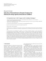
(1) Probability of target-nodes being localized comparison:
here, we calculate the probability of target-nodes being
localized in MANETs with a radius larger than half of
the base-nodes coverage radius (0.5R
max
). Figure 4 depicts
the following: (1) as the MANET coverage radius increases
from 0.5R
max
to 1.6R
max
, the probability of target-nodes
beinglocalizeddecreasesfrom1toabout0.8(forGPS-
aided DOA fusion), 0.55 (for GPS-aided TOA fusion), and
0.49 (for semidistributed multinode TOA-DOA fusion); (2)
with the same MANETs coverage radius, the probability of
target-nodes being localized in the semidistributed method
is always lower than the other two methods.
(2) Point CEP verification: here, we generate the numer-
ical results of point CEP for three localization techniques
and compare them to the corresponding simulation results.
Figure 5 shows the following: (1) the simulation results are
consistent with the numerical results; (2) there is a very small
gap between the simulation and numerical results because
we ignored higher order terms in the computation of the
positioning error; (3) the positioning CEP of the multinode
TOA-DOA fusion with raw estimations is consistent with
that simulated CEP using true values; (4) the positioning
CEP of GPS-aided DOA fusion is much lower than that of the
other two methods. Note that the point CEP only represents
the system performance at a known (but randomly selected)
nodes geometrical distribution. Thus, it might be better or
worse than the average CEP. The average CEP is generated
over a large number of point CEPs.
(3) Average CEP: here, we compare the average CEP of the
three localization techniques considering four parameters:
012345678 9
β
0
0.2
0.4
0.6
0.8
1
CEP
TOA-DOA 5-base-node
TOA-DOA 4-base-node
TOA-DOA 3-base-node
GPS+TOA 5-base-node
GPS+TOA 4-base-node
GPS+TOA 3-base-node
GPS+DOA 5-base-node
GPS+DOA 4-base-node
GPS+DOA 3-base-node
Figure 6: Average CEP comparison versus base-nodes number with
R
max
= 80σ
R
, σ
θ
= 2
◦
, and the ratio Z = 0.5.
the number of base-nodes in the MANET, MANET coverage
radius, DOA estimation standard deviation, and Z
= σ
2
G
/σ
2
R
.
The results are shown in Figures 6, 7, 8,and9. These
figures show (1) all methods perform better as the number
of base-nodes increases; (2) the performance of GPS-aided
TOA fusion is independent of MANET coverage radius,
but the performance of other two techniques decreases as
the MANET coverage radius increases; (3) the performance
of the semidistributed multinode TOA-DOA fusion and
GPS-aided DOA fusion decreases as the DOA estimation
error increases; (4) as the ratio Z
= σ
2
G
/σ
2
R
increases,
the performance of GPS-aided TOA fusion and GPS-aided
DOA fusion decreases, while the semidistributed multinode
TOA-DOAfusionisnotaffected by GPS performance; (5)
considering R
max
= 80σ
R
, σ
θ
= 1
◦
or 2
◦
,andZ = σ
2
G
/σ
2
R
≥
0.5, semidistributed multinode TOA-DOA fusion performs
the best and GPS-aided DOA fusion performs the worst.
5.3. Discussions
The semidistributed multinode TOA-DOA fusion localiza-
tion technique takes the advantages of the base-nodes’ prop-
erty, the capability of localizing other nodes independently;
hence, it does not depend on GPS to localize base-node
in MANETs. Accordingly, it is applicable in GPS-denied
environments as well.
As discussed in Section 2.4, the semidistributed fusion
method suffers from the coordinate transformation. The
probability of target-nodes being not localized by the
reference base-node via any hop increases as the MANET
12 EURASIP Journal on Advances in Signal Processing
012345678 9
β
0
0.2
0.4
0.6
0.8
1
CEP
TOA-DOA 80
σ
R
GPS+TOA 80
σ
R
GPS+TOA 160
σ
R
GPS+TOA 240
σ
R
TOA-DOA 160
σ
R
GPS+DOA 80
σ
R
TOA-DOA 240
σ
R
GPS+DOA 160
σ
R
GPS+DOA 240
σ
R
Figure 7: Average CEP comparison versus MANET radius with 5
base-nodes, σ
θ
= 2
◦
, and the ratio Z = 0.5.
coverage radius increases from half of base-node coverage
radius. In this case, the probability of target-nodes that are
not localized in the main coordinates increases. But GPS-
aided TOA and DOA fusion methods do not suffer from
coordinate transformation. In these two methods, all base-
nodes and target-nodes are localized in earth-centered earth-
fixed (ECEF) Cartesian coordinates; hence, no coordinates’
transformation is needed. In any MANET scale, as long as
a target-node’s TOA (DOA) is estimated by at least 3 (2)
base-nodes, it would be localized in the ECEF Cartesian
coordinates. Finally, because GPS-aided DOA fusion tech-
nique needs only two base-nodes for localization, it is less
vulnerable to coverage radius compared to GPS-aided TOA
fusion.
The positioning error generated by DOA estima-
tion increases as the target-node and base-node distance
increases; however, the positioning error generated by TOA
estimation remains unchanged. Hence, the average position-
ing performance of the semidistributed technique would be
high (low) in a moderate (large) scale MANET.
The GPS-aided DOA fusion error is high. The reason
is explained as follows. In the GPS-aided DOA fusion, the
total DOA estimation error is due to two factors: base-node
DOA estimation error and DOA estimation error generated
by GPS positioning error. When the base-node and target-
node distance is low, the DOA estimation error generated
by GPS would be high and it leads to a high positioning
error. In addition, when the base-node and target-node
distance is high, the base-node DOA estimation error would
012345678 9
β
0
0.2
0.4
0.6
0.8
1
CEP
TOA-DOA fusion, σ
θ
= 0.5
◦
TOA-DOA fusion, σ
θ
= 1
◦
TOA-DOA fusion, σ
θ
= 2
◦
GPS+DOA, σ
θ
= 0.5
◦
GPS+TOA
GPS+DOA, σ
θ
= 1
◦
GPS+DOA, σ
θ
= 2
◦
Figure 8: Average CEP comparison versus DOA estimation error
with 5 base-nodes, R
max
= 80σ
R
, σ
θ
= 2
◦
, and the ratio Z = 0.5.
be dominant, which also translated to a high positioning
error due to high distance.
In GPS-aided TOA fusion, the TOA estimation error
includes base-node TOA estimation error and TOA estima-
tion error generated by GPS positioning error. These two
errors are independent of the distance between base-node
and target-node. Hence, average GPS-aided TOA fusion
performance is independent of the MANET scale as long as
all base-nodes can localize all target-nodes.
The semidistributed multinode TOA-DOA fusion can
be applied to MANETs in GPS denied environments. In
the GPS available environments and all base-nodes localize
all target-nodes, the semidistributed localization method
is suitable for moderate scale MANETs and GPS-aided
TOA fusion is suitable for large scale MANETs. Finally, it
should be noted that the performance evaluation discussed
here would be applicable to the centralized scheme, if the
centralized scheme applies the same reference base-node
selection method used in the semidistributed scheme.
For simplicity, we assumed TOA and DOA estimation
errors are independent and have identical zero mean Gaus-
sian distributions. However, in general, TOA and DOA
estimation errors are functions of many variables including
signal-to-noise ratio (SNR), bandwidth, channel multipath
effects, and the availability of LOS [36, 37]. When LOS
signal is available and it is stronger than NLOS signal,
(a) TOA estimation errors can be considered zero mean
Gaussian random variables with their variance normalized
with respect to the target-node and base-node distance (as
distance increases, TOA estimation error variance increases)
[38]; and, (b) the PDF of DOA estimation error fits Laplacian
Z. Wang and S. Zekavat 13
0123456789
β
0
0.2
0.4
0.6
0.8
1
CEP
TOA-DOA fusion
GPS+TOA, ratio
= 0.5
GPS+TOA, ratio
= 1
GPS+TOA, ratio
= 2
GPS+DOA, ratio
= 0.5
GPS+DOA, ratio
= 1
GPS+DOA, ratio
= 2
Figure 9: Average CEP comparison versus different ratio Z with 5
base-nodes, R
max
= 80σ
R
,andσ
θ
= 2
◦
.
distribution [39]. Whereas in the scenario that LOS is not
available or LOS and NLOS signal power are comparable, the
statistics of TOA and DOA estimation errors are complicated
and hard to compute [40]. In addition, depending on the
nature of channels, the TOA and DOA estimation errors
might become independent [39]orcorrelated[41].
If the PDF of the TOA and DOA estimation errors are
not identical, the joint distribution of Δ
x
(T)
j
and Δy
(T)
j
would
be hard to compute (in the scenario that the PDF of TOA
and DOA estimationerrors are identical zero mean Gaussian,
we use (19) to calculate the joint PDF of Δ
x
(T)
j
and Δy
(T)
j
).
Accordingly, the fusion CEP would be difficult to evaluate.
Thus, making any conclusion would not be plausible.
The performance of the semidistributed multinode TOA-
DOA fusion is altered by the variances of the positioning
error over x and y axes defined in (10), which depends
on base-nodes localization variance (calculated in (4)) and
target-node localization variance (calculated in (7)). If DOA
and TOA estimation errors are correlated, then an additional
term, that is, a function of their correlation coefficient
would appear in (4)and(7). This additional term ultimately
degrades the performance of the fusion in the proposed
semidistributed technique.
The other two techniques, that is, GPS-aided TOA fusion
and GPS-aided DOA fusion only need the estimation of
TOA or DOA. Therefore, in the first review, one may deduce
that the performance of GPS-aided TOA fusion and GPS-
aided DOA fusion may not be altered by the correlation
of TOA and DOA estimation errors. But, let us see what
may impact (or increase) the correlation of TOA and DOA
estimation errors. We predict that multipath environment
may impact (or increase) the correlation of TOA and DOA
estimation errors. Why? Because the estimation performance
of TOA and DOA reduces as the channel multipath effect
increases. Thus, higher correlation might be translated into
lower performance of GPS-aided TOA fusion and GPS-
aided DOA fusion as well. Accordingly, it is hard to make a
solid conclusion when comparing our technique with GPS-
aided TOA fusion and GPS-aided DOA fusion when TOA
and DOA estimation errors are considered correlated. This
subject may need a separate fundamental investigation.
6. CONCLUSIONS
In this paper, we theoretically derive and compare the
point CEP of the semidistributed multinode TOA-DOA
fusion, GPS-aided TOA fusion, and GPS-aided DOA fusion
localization techniques. In addition, we verify the results via
simulation, and compare the average CEP of these three
localization techniques under the same nodes’ geometrical
distribution, and the same estimation error variance.
Simulation results confirm that the semidistributed
multinode TOA-DOA fusion localization technique is not
suitable for MANETs with radius larger than half of base-
nodes coverage radius. In the condition of MANET coverage
radius smaller than or equal to half of base-nodes coverage
radius, the semidistributed multinode TOA-DOA fusion
localization technique leads to a better performance in
moderate scale MANETs. GPS-aided TOA fusion localization
technique leads to a better performance in large scale
MANETs. Finally, GPS-aided DOA fusion leads to a lower
performance compared to the other two techniques.
APPENDICES
A. REFERENCE BASE-NODE SELECTION
Two techniques are proposed for base-node selection. The
first approach is optimal, but needs high computational
cost. The second approach is suboptimal. It needs lower
computational cost while its performance is very close to the
optimal technique.
The optimal reference base-node selection minimizes
the average mean square positioning circular error of the
MANET. The selection method follows (a) let i
= 1; (b)
assume base-node i is the reference base-node, localize non-
reference base-nodes, and cluster the MANET; (c) localize all
m target-nodes in the main coordinates, and generate average
mean square positioning circular error for this selection
(1/m)
m
j
=1
E(Δr
2
j,i
) using (16); (d) if i<n,replacei with
i + 1 and go to step (b); (e) select the base-node, v, with the
minimized average mean square positioning circular error as
the reference base-node as follows:
v
optimal
= arg
i
min
1
m
m
j=1
E
Δr
2
j,i
. (A.1)
In the optimal method, all target-nodes are localized n
times via data fusion, this leads to high time and power
consumption. To reduce the power and time consumption,
14 EURASIP Journal on Advances in Signal Processing
we apply a suboptimal selection scheme. Considering (10)
and (16), the upper bound of
m
j
=1
E(Δr
2
j,i
) corresponds to
m
j=1
E
Δr
2
j,i
=
m
j=1
⎛
⎜
⎜
⎝
1
n
k=1
1/σ
2
x
(T)
ik j
+
1
n
k=1
1/σ
2
y
(T)
ik j
⎞
⎟
⎟
⎠
<
m
j=1
min
k
σ
2
x
(T)
ik j
+min
k
σ
2
y
(T)
ik j
≤
m
j=1
σ
2
x
iij
+ σ
2
y
iij
=
m
j=1
σ
2
R
+ σ
2
θ
R
(T,t)
ij
2
.
(A.2)
Here, R
(T,t)
ij
is the true distance between base-node i and
target-node j. σ
2
R
and σ
2
θ
are constants; hence, the optimal
selection technique of (A.1) can be replaced by the subop-
timal technique that follows
v
sub-optimal
= arg
i
min
m
j=1
R
(T,t)
ij
2
. (A.3)
In the suboptimal reference-node selection method, the
distance from base-nodes to target-nodes is measured once,
and only distance square summation is calculated n times.
This highly reduces the computation cost and complexity. In
addition, using this method, time and power would be saved.
B. CROSS-CORRELATION CALCULATION
The covariance of Δ
x
(T)
j
and Δy
(T)
j
corresponds to
ρσ
x
(T)
j
σ
y
(T)
j
= E
Δx
(T)
j
·Δy
(T)
j
. (B.1)
Incorporating (12)in(B.1)leadsto
ρσ
x
(T)
j
σ
y
(T)
j
=
n
i=1
p
ij
q
ij
E
Δx
(T)
1ij
·Δy
(T)
1ij
. (B.2)
In (B.2), if i
= 1, the target-node j’s positioning information
is provided by the reference base-node and the error is one-
hop positioning error, which does not include the coordinate
transformation error. Accordingly, in (9), Δ
x
(B)
1i
= 0and
Δ
y
(B)
1i
= 0. Now, incorporating the results of (6)in(9), the
one-hop positioning error covariance corresponds to
E
Δx
(T)
11j
·Δy
(T)
11j
=
σ
2
R
−σ
2
θ
R
(T,t)
2
1j
sin θ
(T,t)
1j
cos θ
(T,t)
1j
.
(B.3)
And, if i
/
=1, the target-node j’s positioning information
is provided by nonreference base-node and the error is
two-hop positioning error, which includes the coordinate
transformation error. Considering (3), (6), and (9), the two-
hop positioning error covariance would correspond to
E
Δx
(T)
1ij
·Δy
(T)
1ij
=
σ
2
R
−σ
2
θ
R
(B,t)
2
1i
sin θ
(B,t)
1i
cos θ
(B,t)
1i
+
σ
2
R
−σ
2
θ
R
(T,t)
2
ij
sin θ
(T,t)
ij
cos θ
(T,t)
ij
.
(B.4)
Incorporating (B.3)and(B.4)in(B.2), we can calculate the
covariance of Δ
x
(T)
j
and Δy
(T)
j
, and we can achieve
ρσ
x
(T)
j
σ
y
(T)
j
/
=0. (B.5)
Hence, Δ
x
(T)
j
and Δy
(T)
j
are not independent.
C. POINT PDF DERIVATION
In (12), Δ
x
(T)
j
and Δy
(T)
j
are jointly Gaussian, and Δr
j
=
Δx
(T)
2
j
+ Δy
(T)
2
j
; hence, the CDF of Δr
j
corresponds to
F
point,Δr
j
Δr
j
=
Δr
j
−Δr
j
X
−X
f
Δx
(T)
j
,Δy
(T)
j
Δx
(T)
j
, Δy
(T)
j
dΔx
(T)
j
dΔy
(T)
j
,
(C.1)
where X denotes
Δr
2
j
−Δy
(T)
2
j
.
Differentiating the CDF with respect to Δr
j
leads to the
PDF of Δr
j
as follows:
f
point,Δr
j
Δr
j
=
Δr
j
−Δr
j
Δr
j
Δr
2
j
−Δy
2
j
×
f
Δx
(T)
j
,Δy
(T)
j
Δr
2
j
−Δy
(T)
2
j
, Δy
(T)
j
+ f
Δx
(T)
j
,Δy
(T)
j
−
Δr
2
j
−Δy
(T)
2
j
, Δy
(T)
j
dΔy
(T)
j
.
(C.2)
Let Δ
y
(T)
j
= Δr
j
·sin φ, then
Δr
2
j
−Δy
(T)
2
j
= Δr
j
·cos φ,
dΔy
j
= Δr
j
·cos φ·dφ, φ ∈ [−π/2, π/2]. Accordingly, (C.2)
leads to
f
point,Δr
j
Δr
j
=
π/2
−π/2
Δr
j
f
Δx
(T)
j
,Δy
(T)
j
Δr
j
cos φ, Δr
j
sin φ
+ f
Δx
(T)
j
,Δy
(T)
j
−
Δr
j
cos φ, Δr
j
sin φ
dφ.
(C.3)
Incorporating (19) into (C.3), we have
f
point,Δr
j
Δr
j
=
Δr
j
2π|Λ|
0.5
×
π/2
−π/2
exp
σ
2
y
(T)
j
cos
2
φ − Q
−2|Λ|
Δr
2
j
+exp
σ
2
y
(T)
j
cos
2
φ + Q
−2|Λ|
Δr
2
j
dφ,
(C.4)
where Q denotes ρσ
x
(T)
j
σ
y
(T)
j
sin 2φ + σ
2
x
(T)
j
sin
2
φ.
Z. Wang and S. Zekavat 15
Because, 2cos
2
φ = 1+cos2φ, and 2sin
2
φ = 1 − cos 2φ,
(B.5) corresponds to
f
point,Δr
j
Δr
j
=
Δr
j
2π|Λ|
0.5
exp
σ
2
y
(T)
j
+ σ
2
x
(T)
j
−4|Λ|
Δr
2
j
×
π/2
−π/2
exp
W −2ρσ
x
(T)
j
σ
y
(T)
j
sin 2φ
−4|Λ|
Δr
2
j
+exp
W +2ρσ
x
(T)
j
σ
y
(T)
j
sin 2φ
−4|Λ|
Δr
2
j
dφ,
(C.5)
where W denotes (σ
2
y
(T)
j
−σ
2
x
(T)
j
)cos2φ.
Let A
= (Δr
j
/|Λ|
0.5
) exp(((σ
2
y
(T)
j
+ σ
2
x
(T)
j
)/ − 4|Λ|)Δr
2
j
),
B
= σ
2
y
(T)
j
− σ
2
x
(T)
j
, C = 2ρσ
x
(T)
j
σ
y
(T)
j
, γ = Δr
2
j
√
B
2
+ C
2
/4|Λ|,
cos β
= B/
√
B
2
+ C
2
,andα = 2φ, then dφ = 1/2dα,
α
∈ [−π, π]. Incorporating these parameters, (C.5)would
be equal to
f
point,Δr
j
Δr
j
=
A
4π
π
−π
exp
−
γ·cos(α+β)
+exp
−
γ·cos(α−β)
dα.
(C.6)
Here, g(α)
= exp(−γ·cos(α)) is an even periodic function
with period of 2π.Hence,(C.6) is simplified to
f
point,Δr
j
Δr
j
=
A
π
·
π
0
exp(−γ·cos α)dα
=
A
π
·
π
0
exp(γ·cos α)dα
= A·I
0
(γ).
(C.7)
In (C.7), I
0
(γ) = 1/π
π
0
e
γ cos φ
dφ is the modified Bessel
function of the first kind and zero order. In addition,
A
=
Δr
j
|Λ|
0.5
exp
⎛
⎜
⎝
σ
2
y
(T)
j
+ σ
2
x
(T)
j
−4|Λ|
Δr
2
j
⎞
⎟
⎠
=
Δr
j
|Λ|
0.5
exp
Λ
11
+ Λ
22
−4|Λ|
Δr
2
j
,
γ =
Δr
2
j
√
B
2
+ C
2
4|Λ|
=
Δr
2
j
(Λ
22
−Λ
11
)
2
+ Λ
2
12
4|Λ|
.
(C.8)
Hence,
f
point,Δr
j
Δr
j
=
Δr
j
|Λ|
0.5
exp
Λ
11
+Λ
22
−4|Λ|
Δr
2
j
·
I
0
Δr
2
j
(Λ
22
−Λ
11
)
2
+Λ
2
12
4|Λ|
.
(C.9)
REFERENCES
[1] K. Amouris, “Position-based broadcast TDMA scheduling for
mobile ad-hoc networks (MANETS) with advantaged nodes,”
in Proceedings of IEEE Military Communications Conference
(MILCOM ’05), vol. 1, pp. 252–257, Atlatnic City, NJ, USA,
October 2005.
[2] E. C. Haddad, C. Despins, and P. Mermelstein, “Capacity
gain of zone division for a position-based resource allocation
algorithm in WCDMA uplink data transmission,” in Proceed-
ings of the 14th IEEE on Personal, Indoor and Mobile Radio
Communications (PIMRC ’03), vol. 1, pp. 597–601, Beijing,
China, September 2003.
[3] V. Sumathy, P. Narayanasmy, K. Baskaran, and T. Puru-
sothaman, “GLS with secure routing in ad-hoc networks,”
in Proceedings of the Conference on Convergent Technologies
for Asia-Pacific Region (TENCON ’03), vol. 3, pp. 1072–1076,
Bangalore, India, October 2003.
[4] S. M. M. Rahman, M. Mambo, A. Inomata, and E. Okamoto,
“An anonymous on-demand position-based routing in mobile
ad hoc networks,” in Proceedings of International Symposium
on Applications and the Internet (SAINT ’06), pp. 300–306,
Phoenix, Ariz, USA, January 2006.
[5] J. Xie and L. Huang, “Specification and verification of position
based routing for mobile ad hoc system,” in Proceedings of
the 5th International Conference on Computer and Information
Technology (CIT ’05), pp. 406–409, Shanghai, China, Septem-
ber 2005.
[6] N. Bulusu, J. Heidemann, and D. Estrin, “GPS-less low-cost
outdoor localization for very small devices,” IEEE Personal
Communications, vol. 7, no. 5, pp. 28–34, 2000.
[7] Y. Shang, W. Ruml, Y. Zhang, and M. P. J. Fromherz,
“Localization from mere connectivity,” in Proceedings of the
4th Internat ional Symposium on Mobile Ad Hoc Networking
and Computing (MobiHoc ’03), pp. 201–212, Annapolis, Md,
USA, June 2003.
[8] L. Hu and D. Evans, “Localization for mobile sensor net-
works,” in Proceedings of the 10th Annual International Confer-
ence on Mobile Computing and Networking (MOBICOM ’04),
pp. 45–57, Philadelphia, Pa, USA, September 2004.
[9] S. Zhou and J. K. Pollard, “Position measurement using
Bluetooth,” IEEE Transactions on Consumer Electronics, vol. 52,
no. 2, pp. 555–558, 2006.
[10] T. Locher, R. Wattenhofer, and A. Zollinger, “Received-
signal-strength-based logical positioning resilient to signal
fluctuation,” in Proceedings of the 6th International Con-
ference on Software Engineering, Artificial Intelligence, Net-
working and Parallel/Distributed Computing and 1st ACIS
International Workshop on Self-Assembling Wireless Networks
(SNPD/SAWN ’05), pp. 396–402, Towson, Md, USA, May
2005.
[11] H. Karimi and P. Krishnamurthy, “Real-time routing in
mobile networks using GPS and GIS techniques,” in Proceed-
ings of the 34th Annual Hawaii International Conference, p. 255,
Maui, Hawaii, USA, January 2001.
[12] A. Boukerche and S. Rogers, “GPS query optimization in
mobile and wireless networks,” in Proceedings of the 6th IEEE
Symposium on Computers and Communications (ISCC ’01),pp.
198–203, Hammamet, Tunisia, July 2001.
[13] M. A. Spirito and A. G. Mattioli, “On the hyperbolic posi-
tioning of GSM mobile stations,” in Proceedings of the URSI
International Symposium on Signals, Systems, and Electronics
(ISSSE ’98), pp. 173–177, Pisa, Italy, September-October 1998.
16 EURASIP Journal on Advances in Signal Processing
[14] K. C. Ho and Y. T. Chan, “Solution and performance analysis
of geolocation by TDOA,” IEEE Transactions on Aerospace and
Electronic Systems, vol. 29, no. 4, pp. 1311–1322, 1993.
[15] S. S. Ghidary, T. Tani, T. Takamori, and M. Hattori, “A new
home robot positioning system (HRPS) using IR switched
multi ultrasonic sensors,” in Proceedings of the IEEE Interna-
tional Conference on Systems, Man, and Cybernetics (SMC ’99),
vol. 4, pp. 737–741, Tokyo, Japan, October 1999.
[16] J M.Lee,D.H.Lee,H.An,N.Huh,M.K.Kim,andM.H.
Lee, “Ultrasonic satellite system for the positioning of mobile
robots,” in Proceedings of the 30th Annual Conference of IEEE
Industrial Electronics Society (IECON ’04), vol. 1, pp. 448–453,
Busan, Korea, November 2004.
[17] D. Niculescu and B. Nath, “Ad hoc positioning system (APS)
using AOA,” in Proceedings of the 22nd Annual Joint Conference
of the IEEE Computer and Communications Societies (INFO-
COM ’03), vol. 3, pp. 1734–1743, San Francisco, Calif, USA,
March-April 2003.
[18] S. Sayeef, U. K. Madawala, P. G. Handley, and D. Santoso,
“Indoor personnel tracking using infrared beam scanning,”
in Proceedings of IEEE Position Location and Navigation
Symposium (PLANS ’04), pp. 698–705, Monterey, Calif, USA,
April 2004.
[19] A. N. Bishop, P. N. Pathirana, B. Fidan, B. D. O. Anderson,
and G. Mao, “Passive angle measurement based localization
consistency via geometric constraints,” in Proceedings of
Information, Decision and Control Conference (IDC ’07),pp.
199–204, Adelaide, Australia, February 2007.
[20] H. Tong and S. A. Zekavat, “A novel wireless local position-
ing system via a merger of DS-CDMA and beamforming:
Probability-of-detection performance analysis under array
perturbations,” IEEE Transactions on Vehicular Technology, vol.
56, no. 3, pp. 1307–1320, 2007.
[21] Z. Wang and S. A. Zekavat, “MANET localization via multi-
node TOA-DOA optimal fusion,” in Proceedings of IEEE
Military Communications Conference (MILCOM ’06), pp. 1–7,
Washington, DC, USA, October 2006.
[22] Y. Qi and H. Kobayashi, “On relation among time delay
and signal strength based geolocation methods,” in Proceed-
ings of IEEE Global Telecommunications Conference (GLOBE-
COM ’03), vol. 7, pp. 4079–4083, San Francisco, Calif, USA,
December 2003.
[23] T Y. Chen, C C. Chiu, and T C. Tu, “Mixing and combining
with AOA and TOA for the enhanced accuracy of mobile
location,” in Proceedings of the 5th European Personal Mobile
Communications Conference (EPMCC ’03), pp. 276–280, Glas-
gow, UK, April 2003.
[24] S L. Dong, J M. Wei, T. Xing, and H T. Liu, “Constraint-
based fuzzy optimization data fusion for sensor network
localization,” in Proceedings of the 2nd International Conference
on Semantics Knowledge and Grid (SKG ’06), p. 59, Guilin,
China, November 2006.
[25] A. Brown and J. Nordlie, “Integrated GPS/TOA navigation
using a positioning and communication software defined
radio,” in Proceedings of IEEE/ION Position, Location, and
Navigation Symposium (PLANS ’06), pp. 147–152, San Diego,
Calif, USA, April 2006.
[26] T. Eren, W. Whiteley, and P. N. Belhumeur, “Using angle
of arrival (bearing) information in network localization,”
in Proceedings of the 45th IEEE Conference on Decision and
Control (CDC ’06), pp. 4676–4681, San Diego, Calif, USA,
December 2006.
[27] D H. Shin and T K. Sung, “Comparisons of error character-
istics between TOA and TDOA positioning,” IEEE Transactions
on Aerospace and Electronic Systems, vol. 38, no. 1, pp. 307–311,
2002.
[28] E. D. Kaplan, Understanding GPS: Principles and Applications,
Telecommunications Library, Artech House, Boston, Mass,
USA, 1996.
[29] A. G. Dempster, “Dilution of precision in angle-of-arrival
positioning systems,” Electronics Letters, vol. 42, no. 5, pp. 291–
292, 2006.
[30] J. T. Gillis, “Computation of the circular error probability inte-
gral,” IEEE Transactions on Aerospace and Electronic Systems,
vol. 27, no. 6, pp. 906–910, 1991.
[31] M. Pourkhaatoun, S. A. Zekavat, and J. Pourrostam, “A novel
high resolution ICA-based TOA estimation technique,” in
Proceedings of IEEE Radar Conference, pp. 320–324, Waltham,
Mass, USA, April 2007.
[32] S. A. Zekavat, A. Kolbus, X. Yang, Z. Wang, J. Pourrostam,
and M. Pourkhaatoon, “A novel implementation of DOA
estimation for node localization on software defined radios:
achieving high performance with low complexity,” in Proceed-
ings of IEEE International Conference on Signal Processing and
Communications (ICSPC ’07), Dubai, UAE, November 2007.
[33] J. Pourrostam, S. A. Zekavat, and H. Tong, “Novel direction-
of-arrival estimation techniques for periodic-sense local posi-
tioning systems,” in Proceedings of IEEE Radar Conference,pp.
568–573, Waltham, Mass, USA, April 2007.
[34] J. G. Proakis, Digital Communications, Mcgraw-Hill, New
York, NY, USA, 4th edition, 2001.
[35] D. J. Torrieri, “Statistical theory of passive location systems,”
IEEE Transactions on Aerospace and Electronic Systems, vol. 20,
no. 2, pp. 183–198, 1984.
[36] S. Gezici, H. Kobayashi, and H. V. Poor, “Non-parametric
non-line-of-sight identification,” in Proceedings of the 58th
IEEE Vehicular Technology Conference (VTC ’03), vol. 4, pp.
2544–2548, Orlando, Fla, USA, October 2003.
[37] M. Heidari and K. Pahlavan, “A new statistical model for
the behavior of ranging errors in TOA-based indoor local-
ization,” in Proceedings of IEEE Wireless Communications and
Networking Conference (WCNC ’07), pp. 2566–2571, Hong
Kong, March 2007.
[38] B. Alavi and K. Pahlavan, “Modeling of the distance error
for indoor geolocation,” in Proceedings of IEEE Wireless
Communications and Networking Conference (WCNC ’03), vol.
1, pp. 668–672, New Orleans, La, USA, March 2003.
[39] Q. H.Spencer, B. D. Jeffs, M. A. Jensen, and A. L. Swindlehurst,
“Modeling the statistical time and angle of arrival characteris-
tics of an indoor multipath channel,” IEEE Journal on Selected
Areas in Communications, vol. 18, no. 3, pp. 347–360, 2000.
[40] S. Venkatraman and J. Caffery Jr., “Hybrid TOA/AOA tech-
niques for mobile location in non-line-of-sight environ-
ments,” in Proceedings of IEEE Wireless Communications and
Networking Conference (WCNC ’04), vol. 1, pp. 274–278,
Atlanta, Ga, USA, March 2004.
[41]A.Y.Olenko,K.T.Wong,andE.H O.Ng,“Analytically
derived TOA-DOA statistics of uplink/downlink wireless
multipaths arisen from scatterers on an hollow-disc around
the mobile,” IEEE Antennas and Wireless Propagation Letters,
vol. 2, pp. 345–348, 2003.