Báo cáo hóa học: "Surface Morphological and Nanomechanical Properties of PLD-Derived ZnO Thin Films" docx
Bạn đang xem bản rút gọn của tài liệu. Xem và tải ngay bản đầy đủ của tài liệu tại đây (456.73 KB, 8 trang )
NANO EXPRESS
Surface Morphological and Nanomechanical Properties
of PLD-Derived ZnO Thin Films
Sheng-Rui Jian Æ I-Ju Teng Æ Ping-Feng Yang Æ
Yi-Shao Lai Æ Jian-Ming Lu Æ Jee-Gong Chang Æ
Shin-Pon Ju
Received: 11 December 2007 / Accepted: 7 May 2008 / Published online: 21 May 2008
Ó to the authors 2008
Abstract This study reports the surface roughness and
nanomechanical characteristics of ZnO thin films deposited
on the various substrates, obtained by means of atomic
force microscopy (AFM), nanoindentation and nanoscratch
techniques. ZnO thin films are deposited on (a- and c-axis)
sapphires and (0001) 6H-SiC substrates by using the
pulsed-laser depositions (PLD) system. Continuous stiff-
ness measurements (CSM) technique is used in the
nanoindentation tests to determine the hardness and
Young’s modulus of ZnO thin films. The importance of the
ratio (H/E
film
) of elastic to plastic deformation during
nanoindentation of ZnO thin films on their behaviors in
contact-induced damage during fabrication of ZnO-based
devices is considered. In addition, the friction coefficient of
ZnO thin films is also presented here.
Keywords ZnO Á PLD Á AFM Á Nanoindentation Á
Nanoscratch Á Hardness
Introduction
ZnO semiconductor, having a wide direct band gap of
3.37 eV at room temperature, has attracted much attention
because of its wide applications in various optoelectronic
and electronic devices. In addition, it has been considered
as a prime candidate for ultraviolet light emitting diodes
and lasers due to its larger exciton binding energy of
60 meV [1, 2]. In contrast, research on the mechanical
properties has not drawn equal attention. The successful
fabrication of devices based on ZnO thin films requires an
understanding of the mechanical characteristics in addition
to its optical and electrical performances. Due to the
contact loading during processing or application, the per-
formances of these devices can be significantly degraded. It
is of interest to investigate the mechanical characteristics of
materials at nanoscale for device applications.
The mechanical characteristics of materials are size-
dependent. Thin films may have different mechanical
responses from their bulk materials. Until recently, the role
of structural changes under contact loading was largely
underestimated owing to the difficulties in structural
characterizations of thin films affected by the contact
interaction. Nanoindentation is an instrumented depth-
sensing technique that has enabled the measurement of
mechanical properties from small volumes of materials and
thin films. Such mechanical properties, e.g., hardness and
elastic modulus, can be determined directly from indenta-
tion load versus displacement curves [3–6]. In fact, the
load-displacement curves obtained during nanoindentation
can be viewed as ‘‘fingerprints’’ that contain much
S R. Jian (&)
Department of Materials Science and Engineering,
I-Shou University, Kaohsiung 840, Taiwan, ROC
e-mail:
I J. Teng
Department of Materials Science and Engineering, National
Chiao Tung University, Hsinchu 300, Taiwan, ROC
P F. Yang Á Y S. Lai
Central Labs, Advanced Semiconductor Engineering,
Kaohsiung 811, Taiwan, ROC
J M. Lu Á J G. Chang
National Center for High-Performance Computing, National
Applied Research Laboratories, No. 28, Nanke 3rd Rd.,
Sinshih Township, Tainan County 74147, Taiwan, ROC
S P. Ju
Department of Mechanical and Electro-Mechanical Engineering;
Center for Nanoscience and Nanotechnology, National
Sun-Yat-Sen University, Kaohsiung 804, Taiwan, ROC
123
Nanoscale Res Lett (2008) 3:186–193
DOI 10.1007/s11671-008-9134-4
information about deformation mechanisms [7–9]. It
appears meaningful to extend the nanoindentation study to
the ZnO thin films, in merit of both basic research and
technological applications. In addition, nanoscratch tech-
nique can be used to characterize the nanotribological
properties of ZnO thin films by scratching the ZnO surface
using a diamond tip and recording the coefficient of
friction, in situ scratch depth and residual depth. However,
although nanoscratch technique has been widely used to
evaluate the nanotribological properties of metallic,
ceramic, and polymeric thin films materials [10–12], to our
knowledge, much less attention has been done on ZnO thin
films.
Herein, the purpose of the present work is to report on
the results of experiments designed to prepare ZnO thin
films on various substrates by using a pulsed-laser depo-
sition (PLD) system and, to investigate the surface
morphological and mechanical behaviors of ZnO thin films
by using atomic force microscopy (AFM) and nanoinden-
tation/nanoscratch techniques, respectively, with particular
reference to the effects of substrates on mechanical
properties of thin films/substrates systems.
Experimental Details
The Growth Conditions of ZnO Thin Films
ZnO thin films were grown on (0001) (c-oriented), ð11
20Þ
(a-oriented) sapphire and (0001) 6H-SiC substrates by
using PLD system, which is popularly adapted in growing
ZnO layers [13, 14]. A KrF excimer laser (Lambda physik
210, k = 248 nm) is employed and the beam was focused
to produce an energy density of * 5–7 J/cm
2
with 10 Hz
repetition rate at a 45
o
angle of incidence on a commercial
hot pressed stoichiometric ZnO (99.99% purity) target.
The thin films were deposited at * 0.625 A
˚
/sec growth
rate at 600 °C substrate temperature under base vacuum of
3.5 9 10
-9
torrs, and then in-situ annealed at 700 °C for
1 h. No oxygen gas flow was introduced during the
growth and annealing. In all cases, the ZnO epilayers
are * 600 nm thick.
Surface Features Characterizations
Samples are imaged at room temperature using a com-
mercial atomic force microscopy (AFM, Nanoscope III,
Digital Instruments) equipped with soft (version 4.32) for
images processing and roughness calculation. For tapping
mode we used rectangular silicon cantilevers (nanosensors,
125 lm long, 30 lm wide and 4 lm thick) with a tip radius
of about 10 nm, a normal spring constant of 40 N/m and
resonance frequency of 339 kHz.
The surface roughness can be represented by center line
average (R
a
) and root-mean-square average (RMS)[15]in
the following forms:
R
a
¼
1
n
X
n
i¼1
z
i
jj
; ð1Þ
RMS ¼
ffiffiffiffiffiffiffiffiffiffiffiffiffiffiffi
1
n
X
n
i¼1
z
2
i
s
: ð2Þ
The center line is the line that divides the profile in such
a way such that the net deviation is zero. Both R
a
and RMS
measure the average vertical deviation of surface profile
from the center line. It should be noted that these
parameters can only be used to compare sample surfaces
generated by the same method in Ref. [16].
Nanoindentation and Nanoscratch Measurements
The nanoindentation measurements were performed on a
Nanoindenter MTS NanoXP
Ò
system (MTS Cooperation,
Nano Instruments Innovation Center, TN, USA) with a
diamond pyramid-shaped Berkovich-type indenter tip,
whose radius of curvature is 50 nm. The mechanical prop-
erties (the hardness and Young’s modulus) of ZnO thin films
were measured by nanoindentation with a continuous stiff-
ness measurements (CSM) technique [17]. In this technique,
a small sinusoidal load with known frequency and amplitude
was superimposed onto the quasi-static load. It results in a
modulation of the indenter displacement that is phase shifted
in response to the excitation force. The stiffness, S, of the
material, and the damping, wC, along indentation loading
can be respectively calculated using Eqs. 3 and 4 expressed
below. The hardness and elastic modulus are, then, calcu-
lated by putting the obtained stiffness data into Eqs. 5–7,
respectively. In this way, the hardness (H) and reduced
elastic modulus (E
r
) as a function of penetration depth are
determined for a single loading/unloading cycle [18].
S ¼
1
P
max
hðwÞ
cos U ÀðK
s
À mw
2
Þ
À K
À1
f
"#
À1
ð3Þ
wC ¼
P
0
hðwÞ
sin U ð4Þ
H ¼
P
max
A
c
ð5Þ
S ¼ 2E
r
h
c
ffiffiffiffiffi
A
c
p
r
ð6Þ
Nanoscale Res Lett (2008) 3:186–193 187
123
1
E
r
¼
1 Àv
2
film
ÀÁ
E
film
þ
1 Àv
2
i
ÀÁ
E
i
ð7Þ
where P
max
and h(w) are denoted as the driving force and the
displacement response of the indenter, respectively; U is the
phase angle between P
max
and h(w); m is the mass of the
indenter column; K
s
is spring constant at the vertical
direction; K
f
is frame stiffness; m, K
s
and K
f
are all constant
values for specified indentation system; w is angular speed
which equals to 2pf; f is the driven frequency of the ac signal
of 45 Hz for this work, which is used to avoid the sensitivity
to thermal drift; the loading resolution of the system was 50
nN; and A
c
is contact area when the material in contact
with indenter being loaded at P
max
. E
film
and v
film
are elastic
modulus and Poisson’s ratio for thin films and, E
i
(= 1,141
GPa) and v
i
(= 0.07) are the same parameters for a indenter.
Here, v
film
is set to be 0.25 [19] for current analysis.
The area function, which is used to calculate contact
area, A
c
, was carefully calibrated by using fused silica as
the standard sample prior to the nanoindentation experi-
ments. The nanoindentation tests were carried out in the
following sequence: first of all, the Berkovich indenter was
brought into contact with the surface at a constant strain
rate of 0.05 s
-1
. The load was then held at the maximum
value for 30 s in order to determine the creep behavior. The
Berkovich indenter was then withdrawn from the surface at
the same rate until 10% of the maximum load was reached.
This constant strain rate was chosen such that the strain-
hardening effect can be avoided during the measurements.
And, at least 10 indents were performed on ZnO thin films.
The nanoindentations were sufficiently spaced to prevent
from mutual interactions.
Scratch testing was measured using a Nano Indenter
XP
Ò
system with options for lateral-force measurements.
The procedure was similar that presented in detail else-
where [20]. The normal indenter load was linearly ramped
from the minimum to maximum (0–5 mN) during the
scratching. The translation speed was typically 50 lm/s.
The test was repeated four times for each system. The
average values of the coefficient of friction (l) of four
scratched at the same maximum constant normal load was
used to estimate the friction behavior of the samples. After
scratching, the wear tracks were imaged by AFM.
Results and Discussion
Surface Features
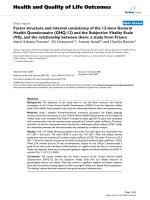
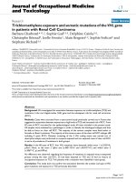
Typical AFM images of ZnO thin films deposited on the
three substrates of a-axis sapphire, c-axis sapphire, and
(0001) 6H-SiC, respectively, are presented in Fig. 1, where
the island-like surfaces are clearly visible. From AFM
observations, R
a
and RMS for each specimen are accurately
obtained. Moreover, mechanical characteristics by nano-
indentation are prerequisite to perform under allowably
Fig. 1 AFM images of ZnO thin films deposited on the various
substrates for (a) a-axis sapphire, (b) c-axis sapphire, and (c) (0001)
6H-SiC, respectively
188 Nanoscale Res Lett (2008) 3:186–193
123
smooth surface for specimen requirement and allowable
thermal drift for environmental control, following that
convergent curves of hardness and modulus are obtained.
R
a
and RMS of ZnO thin films deposited on a-sapphire
substrate are presented the smaller value while its crystal
structure is closely arranged. In addition, the R
a
and RMS
of ZnO thin films were summarized in Table 1.
Nanoindentation Analysis
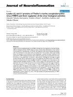
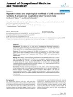
The typical indentation load-displacement curves of all
ZnO thin films are shown in Fig. 2(a). Of note, there is no
manifestly ‘‘pop-in’’ event displayed in the loading part
of all load-displacement curves of ZnO thin films. The
phenomena are very different from the previous studies
[21, 22], which display the multiple ‘‘pop-ins’’ in single-
crystal (wurtzite) ZnO.
The physical mechanisms of the multiple ‘‘pop-ins’’
appearing in the load-displacement curve have been
extensively discussed in the literatures. Among all, crack
formation [23], sudden occurrence of pressure-induced
phase transformation [24] and, generation of slip bands
because of dislocation propagation [9] during the nanoin-
dentation process were identified to have occurred in the
different systems. In contrast, epitaxial layers are expected
to contain more defects like surface steps [25] that are
known to facilitate the onset of plasticity [26]. In addition,
this may be due, in part; pop-in events were attributed to
the very poor defect density prior to the nanoindentation
tests so that the onset of plasticity requires load sufficient
for dislocation nucleation and propagation. In fact, during
this research, no pop-in events are observed.
The displacement dependence of the hardness and
Young’s modulus of ZnO thin films can be obtained
because of the CSM measurements, as illustrated in
Fig. 2(b, c). As displayed in Table 1, which summarizes
the hardness and Young’s modulus for various ZnO
samples obtained from different indentation methods [19,
27–29], the values obtained by using Berkovich indenter
are somewhat larger than those obtained by other methods.
In 2004, Li et al. [30] proposed that the nanoindentation
depth should never exceed 30% of films thickness. From
the presented results, it can be observed that the sudden
drop over the same range of indentation depth (from 40 nm
to 100 nm) wherein the softening occurs and remains
relatively constant. That is, no manifestly substrate effect is
displayed here. Thereby, we can speculate that the dis-
crepancies among the mechanical properties of ZnO thin
films are reasonably explained by the various growth
environments of thin films, the indentation instruments and
operational conditions.
Fig. 2(b) displays the hardness of ZnO thin films cal-
culated by using the method of Oliver and Pharr [18]. The
plot can be divided into two stages, namely, increase and
decrease to constant. The hardness is observed to increase
with increasing the penetration depth at small depth. The
increase in hardness at small penetration depth is usually
attributed to the transition between purely elastic to elastic/
plastic contact whereby the hardness is really the mean
contact pressure. Only under a condition of a fully devel-
oped plastic zone does the mean contact pressure represent
the hardness. When there is no plastic zone, or a partially
formed plastic zone, the mean contact pressure (which is
measured using the Oliver and Pharr method) is less than
the nominal hardness. After the first stage, the hardness
decreases to constant stage and reaches constant values
of ZnO thin films on three various substrates, as listed
in Table 1, respectively. The constant characteristic of
Table 1 The surface roughness and evaluated mechanical properties of ZnO thin films and bulk materials (S R. Jian* et al.)
ZnO fiilm/sapphire ZnO film/c-sapphire ZnO films/(0001) 6H-SiC ZnO films ZnO (bulk)
R
a
2.3 nm* 3.6 nm* 4.1 nm*
RMS 2.8 nm* 4.5 nm* 5.2 nm* 13.5–20.6 nm [19]
H 11.5 ± 0.8 GPa* 7.4 ± 0.1 GPa* 5.9 ± 0.2 GPa* 9.2 ± 0.810.4 ± 0.4 GPa [19] 2.2 ± 0.2 GPa
(a-oriented bulk) [27]
6.6 ± 1.2 GPa [27] 5.7 ± 0.8 GPa [27] 9.3–12.1 GPa [28] 4.8 ± 0.2 GPa
(c-oriented bulk) [27]
8.7 ± 0.2 GPa [29]
E
film
212.2 ± 0.1 GPa* 150.1 ± 5.7 GPa* 117.1 ± 0.4 GPa* 9.2 ± 0.8–10.4 ± 0.4 GPa [19] 163 ± 6 GPa
(a-orientedbulk) [27]
318.2 ± 50 GPa [27] 310.1 ± 40 GPa [27] 103.5–114.4 GPa [28] 143 ± 6 GPa
(c-oriented bulk) [27]
154 ± 5 GPa [29]
H/E
film
0.054 ± 0.004* 0.050 ± 0.002* 0.049 ± 0.001*
l 0.25 ± 0.02* 0.28 ± 0.01* 0.31 ± 0.02*
* The present study
Nanoscale Res Lett (2008) 3:186–193 189
123
hardness is consistent with that of a single material;
therefore, the hardness values at this stage could be
regarded as film-only properties. In addition, a plot of
Young’s modulus of ZnO thin films on three various sub-
strates determined using the method of Oliver and Pharr
[18] is illustrated in Fig. 2(c). The variation of results is
similar to those illustrating in Fig. 2(b); corresponding to
the tendency of increase and decrease to constant of curves.
The values of Young’s modulus for ZnO thin films are also
listed in Table 1.
Nanoscratch Testing
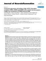
Figures 3(a–c) show wear track appearance for ZnO thin
films deposited on a-axis sapphire, c-axis sapphire, and
(0001) 6H-SiC substrates, respectively. Fig. 3(a) displays a
shallow wear track surface, whereas Fig. 3(b, c) show a
deeper wear track surface. It is important to note that ZnO/
a-axis sapphire has lower surface roughness and higher
hardness while its l remain at lower levels and comparable
to those of the rest two thin films.
Fig. 2 Nanoindentation test results: (a) the typical load-displacement curves for ZnO thin film deposited on the various substrates; (b) hardness-
displacement curves, and (c) Young’s modulus-displacement curves for ZnO thin films
190 Nanoscale Res Lett (2008) 3:186–193
123
Figure 4 is a plot of the friction coefficient (l) versus
scratch length (normal load). The l is calculated by taking
the ratio of the lateral force and the normal load on the
indenter [31]. The fluctuation in the friction coefficient
values is promoted by point-on orientation of the tip or the
layered structure of thin films or it could be owing to
nanoscale fracture events. The evolution of l values shows
small fluctuations and corresponds to mild wear, without
any evidence of catastrophic damage or delamination of
thin films. It was observed that increasing the normal load
from 0.02 to 5 mN, l was almost constant into early period
(0.25 ± 0.02, 0.28 ± 0.01, 0.31 ± 0.02 for three different
substrates are displayed in Fig. 4 and Table 1) despite the
increase of the plastic deformation of ZnO thin films with
the load, which resulted in grooving during scratch. In the
meanwhile, the relationship between l with scratch length
(normal loading) almost was as well. No cracking of thin
films took place, as also verified by our AFM observations
while executing constantly 5 mN scratching loading each
specimen, as illustrated in Fig. 3. In addition, the degree of
Fig. 3 AFM images and cross-
sectional high profiles of
scratches made at a normal load
of 5 mN on ZnO thin films
deposited on (a) a-axis sapphire,
(b) c-axis sapphire, and (c)
(0001) 6H-SiC substrates
Nanoscale Res Lett (2008) 3:186–193 191
123
pile-up phenomenon across the residual profile can be
obtained by AFM; in particular more manifest at the end of
the scratch length each specimen.
In addition, hardness to Young’s modulus ratio (H/E
film
ratio) is a key parameter determining the type of behavior
observed in nanoindentation and nanoscratch [32], i.e., this
ratio can be regarded as a tool to describe values for per-
formance criteria which are important to define the wear
resistance of materials, such as the critical yield pressure
for plastic deformation, the elastic strain to failure and the
fracture toughness. Therefore, a high H/E
film
ratio is often a
reliable indictor of good wear resistance in materials [33].
The values are listed in Table 1. Results indicated that the
best H/E
film
ratio is displayed at ZnO thin film deposited on
a-axis sapphire substrate.
Conclusion
We report in this article structural features and nanome-
chanical characterizations of ZnO thin films deposited on
various substrates by the PLD system using AFM and
nanoindentation techniques, while the nanoscratch resis-
tance and frication coefficients are investigated by
analyzing the scratching processes of thin films.
Results indicate that the hardness of ZnO thin films:
11.5 ± 0.8, 7.4 ± 0.1, and 5.9 ± 0.2 GPa for a-axis sap-
phire, c-axis sapphire, and (0001) 6H-SiC substrates,
respectively. On the other hand, the highest Young’s
modulus of 212.5 ± 0.1 GPa appear at the a-axis sapphire
substrate, while the lowest one of 117.1 ± 0.4 GPa at
(0001) 6H-SiC. In addition, the smoother surface rough-
ness and, a relatively lower friction coefficient equal to
approximately 0.25 ± 0.02 and long wear life are also
displayed at ZnO thin film deposited on a-axis sapphire
substrate. No delamination and evidence of all ZnO thin
films failure are observed in the present scratch tests.
Acknowledgment This work was partially supported by the
National Science Council of Taiwan and I-Shou University, under
Grant No.: NSC 97 - 2218-E-214-003, NSC 96-2221-E492-007-
MY3 and ISU97-07-01-04.
References
1. D.C. Look, J.W. Hemsky, J.R. Sizelove, Phys. Rev. Lett. 82,
2552 (1999)
2. A. Tsukazaki, M. Kubota, A. Ohtomo, T. Onuma, K. Ohtani, H.
Ohno, S.F. Chichibu, M. Kawasaki, Jpn. J. Appl. Phys. 44, L643
(2005)
3. G. Beshkov, G.P. Vassilev, M.R. Elizalde, T.G. Acebo, Mater.
Chem. Phys. 82, 452 (2003)
4. X.D. Li, H. Gao, C.J. Murphy, K.K. Caswell, Nano Lett. 3, 1495
(2003)
5. X. Tao, X. Wang, X.D. Li, Nano Lett. 7, 3172 (2007)
6. C.H. Chien, S.R. Jian, C.T. Wang, J.Y. Juang, J.C. Huang, Y.S.
Lai, J. Phys. D: Appl. Phys. 40, 3985 (2007)
7. S. Ruffell, J.E. Bradby, J.S. Williams, Appl. Phys. Lett. 89,
091919 (2006)
8. E. Le Bourhis, G. Patriarche, Micro. 38, 377 (2007)
9. S.R. Jian, Nanoscale Res. Lett. 3, 6 (2008)
10. B. Bhushank, X.D. Li, Inter. Mater. Rev. 48, 125 (2003)
11. B. Bhushan (ed.), Springer Handbook of Nanotechnology
(Springer, Heidelberg, Germany, 2004)
12. G. Wei, B. Bhushan, N. Ferrell, D. Hansford, J. Vac. Sci.
Technol. A 23, 1856 (2005)
13. A. Tsukazaki, A. Ohtomo, T. Onuma, M. Ohtani, T. Makino, M.
Sumiya, K. Ohtani, S.F. Chichibu, S. Fuke, Y. Segawa, H. Ohno,
H. Koinuma, M. Kawasaki, Nature Mater. 4, 42 (2005)
14. K. Ip, Y.W. Heo, D.P. Norton, S.J. Peatron, J.R. LaRoche, F.
Ren, Appl. Phys. Lett. 85, 1169 (2004)
15. K. Miyoshi, Y.W. Chung, Surface Diagnostics in Tribology:
Fundamental Principles and Applications (World Scientific
Publishing, Singapore, 1993)
16. D. Ca
´
ceres, I. Vergara, R. Gonza
´
lez, E. Monroy, F. Calle, E.
Mun
˜
oz, F. Omne
`
s, J. Appl. Phys. 86, 6773 (1999)
17. X.D. Li, B. Bhushan, Mater. Charact. 48, 11 (2002)
18. W.C. Oliver, G.M. Pharr, J. Mater. Res. 7, 1564 (1992)
19. P.F. Yang, H.C. Wen, S.R. Jian, Y.S. Lai, S. Wu, R.S. Chen,
Microelectron. Reliab. 48, 389 (2008)
20. C. Charitidis, Y. Panayiotatos, S. Logothetidis, Diamond Relat.
Mater. 12, 1088 (2003)
21. S.O. Kucheyev, J.E. Bradby, J.S. Williams, C. Jagadish, M.V.
Swain, Appl. Phys. Lett. 80, 956 (2002)
22. J.E. Bradby, S.O. Kucheyev, J.S. Williams, C. Jagadish, M.V.
Swain, P. Munroe, M.R. Phillips, Appl. Phys. Lett. 80, 4537
(2002)
23. S.J. Bull, J. Phys. D: Appl. Phys. 38, R393 (2005)
24. I. Zarudi, J. Zou, L.C. Zhang, Appl. Phys. Lett. 82, 874 (2003)
25. G. Patriarche, F. Glas, G.L. Roux, L. Largeau, A. Mereuta, J.L.
Benchimol, J. Cryst. Growth
221, 12 (2000)
26. S. Brochard, J. Rabier, J. Grillhe, Eur. Phys. J. AP. 2, 99 (1998)
Fig. 4 Coefficient of friction as a function of the scratch distance
under the normal load from 0.02 to 5 mN for three different samples
192 Nanoscale Res Lett (2008) 3:186–193
123
27. V.A. Coleman, J.E. Bradby, C. Jagadish, P. Munroe, Y.W. Heo,
S.J. Pearton, D.P. Norton, M. Inoue, M. Yano, Appl. Phys. Lett.
86, 203105 (2005)
28. S. Zhao, Y. Zhou, Y. Liu, K. Zhao, S. Wang, W. Xiang, Z. Liu, P.
Han, Z. Zhang, Z. Chen, H. Lu, K. Jin, B. Cheng, G. Yang, Appl.
Surf. Sci. 253, 726 (2006)
29. R. Navamethavan, K.K. Kim, D.K. Hwang, S.J. Park, J.H. Hahn,
T.G. Lee, G.S. Kim, Appl. Surf. Sci. 253, 464 (2006)
30. X.D. Li, H.S. Gao, C.J. Murphy, L.F. Gou, Nano Letters 10, 1903
(2004)
31. T.W. Scharf, J.A. Barnard, Thin Solid Fillms 308–309, 340
(1997)
32. A. Leyland, A. Mattews, Wear 246, 1 (2000)
33. W. Ni, Y.T. Cheng, M. Lukitsch, A.M. Weiner, L.C. Lev, D.S.
Grummon, Wear 259, 842 (2005)
Nanoscale Res Lett (2008) 3:186–193 193
123