Báo cáo hóa học: " Nanoelectrodes for Molecular Devices: A Controllable Fabrication" pdf
Bạn đang xem bản rút gọn của tài liệu. Xem và tải ngay bản đầy đủ của tài liệu tại đây (227.82 KB, 3 trang )
NANO SPOTLIGHTS
Nanoelectrodes for Molecular Devices: A Controllable
Fabrication
Published online: 22 July 2008
Ó to the author 2008
The miniaturization of components for the construction of
useful devices is an essential feature of modern technology.
Their miniaturization permits the assembly of ultra-densely
integrated circuits and faster processors. However, along
with the developing of silicon-based electronics, it is
becoming apparent that intrinsic limitations will prevent
their miniaturization down to the nanoscale. To solve these
problems, an alternative and promising strategy, called the
bottom-up approach, was suggested by an eminent physi-
cist and visionary, Richard Feynman, in 1959. In the
bottom-up approach, one can build nanodevices starting
from atom or molecules. Via this strategy, a series of sig-
nificant advances have been achieved in recent years.
However many problems still exist, hampering its further
development.
This said, the researchers were faced with a puzzling
problem—How can nanoelectrodes with a controllable gap
size be fabricated? This is particularly important because
the fundamental basis of molecular electronics requires the
electrodes to be fabricated with a gap size commensurate to
the size of molecules of interest. Despite reports on suc-
cessful attempts such as break junction, electrochemical
method, and nanowire lithography, the precise control of
the gap size still need be resolved. For instance, it is a
problem to provide a real time characterization during the
fabrication of the nanoelectrodes; thus, the exact gap size is
usually undetectable, leaving the precise control of the gap
size unfeasible and inefficient. Moreover, the existing
methods often are far routine, low yielding and difficult to
implement.
To solve these problems, Chinese scientists have dem-
onstrated a new method based on the electron-beam-
induced deposition (EBID) process to realize a real time
and in situ characterization in nanoelectrode fabrication.
This technique has thus far been successful in easily and
precisely controlling the gap size of the nanoelectrodes.
‘‘The research of molecular electronics was launched in
1974, when Ari Aviram and Mark A. Ratner proposed an
electrical rectifier by a single molecule with suitable
electronic asymmetry. From that time, the fabrication of
nanoelectrodes with a molecular gap size remains a puzzle
for the researchers. This is also the first obstacle we
encountered.’’ Prof. Yunqi Liu explains, ‘‘We tried many
methods; however, the present methods are too fastidious
for us to implement. Most important, we need a real time
and in situ characterization in the fabrication for control-
ling the gap size of nanoelectrodes; however, the present
methods could not afford.’’
‘‘EBID is a maskless process using a high-intensity
electron beam to deposit nanoscale structures on a scanned
surface, and it has been widely used in nanofabrication.’’
Says Prof. Liu ‘‘In the scanning electron microscopy
(SEM) test of carbon nanotubes (CNTs), we found that the
CNTs became broader after electron beam irradiation, and
this should originate from EBID. Based on this finding, we
developed a new method to produce nanoelectrodes.’’
Yunqi Liu, the Professor of Institute of Chemistry at the
Chinese Academy of Sciences in Beijing, P. R. China,
developed the method along with graduate student Dach-
eng Wei. This work has been published in the May 23,
2008 online edition in Nano Letters (‘‘Real time and in situ
control of the gap size of nanoelectrodes for molecular
devices).
‘‘We place a CNT between Au/Ti electrodes on a SiO
2
/
Si wafer, and then cut it at the middle to form a wide
original gap in the range of 10–60 nm. The electrode is
exposed to organic vapor to absorb organic molecules on
the CNT.’’ Prof. Liu describes the process, ‘‘if we place the
123
Nanoscale Res Lett (2008) 3:268–270
DOI 10.1007/s11671-008-9146-0
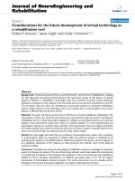
Fig. 1 Schematic diagram of
the process of the fabrication of
a CNT electrode with a
controlled nanogap. (a)
Bridging a CNT between Au/Ti
electrodes. (b) Cutting the CNT
by current breakdown method.
(c) Adsorbing organic
molecules on or in the CNT. (d)
Irradiating the gap of the CNT
by electron beam with in situ
observation in SEM. (Reprinted
with permission from American
Chemical Society)
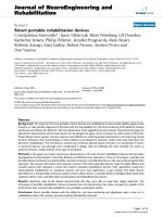
Fig. 2 SEM images of the CNT
nanoelectrodes. (a) SEM images
of a CNT electrode in the EBID
process: (1) just after current
breakdown; (2–5) after an EBID
process of 2, 4, 6, and 10 min,
respectively. (b) CNT
electrodes with a series of gap
sizes fabricated by the EBID
method: (1–5). The left images
are SEM images measured after
the EBID process, the gap sizes
are ca. 2, 4, 6, 8, and 10 nm,
respectively, and the right
images are SEM images
measured before the EBID
process. (c) SEM images of a
nanoelectrode which is made of
single-walled CNTs (1) before
current breakdown, (2) before
the EBID process, and (3) after
about 2 min in the EBID
process. (Reprinted with
permission from American
Chemical Society)
Nanoscale Res Lett (2008) 3:268–270 269
123
electrode in SEM and focus a high-density electron beam
on the area of the gap of the electrode, the irradiated part of
the CNT will gradually become broader, and as a result the
gap becomes narrower. Because this process is observed in
real time and in situ by SEM, we can stop the process at
any time, and then an electrode with the gap size corre-
sponding to our need is obtained’’ (Fig. 1).
Juxtapose to existing methods, the method proposed by
Prof. Liu’s group is very simple and controllable. ‘‘What
we need is a SEM. In previous research, the SEM serves
primarily as a tool to precisely characterize the gap size of
the nanoelectrodes. In our method, the SEM plays two
roles. First, the SEM provides an in situ and real time
characterization of the gap size. Second, the electron beam
of SEM induces broadening of CNTs and narrowing of the
gap. Now it is very simple for us to fabricate nanoelectrodes
with certain gap size. We can fabricate nanoelectrodes with a
series of gap sizes.’’ Prof. Liu says, ‘‘moreover, It is a clean
process without introducing impure atoms and a nonde-
structive process for CNT electrodes’’ (Fig. 2).
The nanoelectrodes produced by this method have a
p-conjugated surface. Prof. Liu et al. tested the nanoelec-
trodes after EBID by Raman, and the Raman spectra
showed that the deposit was sp
2
-rich amorphous carbon,
which offered the nanoelectrodes a p-conjugated surface.
By using these nanoelectrodes, Prof. Liu’s group produced
molecular devices by using DNA molecules.
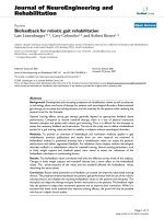
‘‘Since the DNA has a strong p–p interaction with
p-conjugated surface, the DNA molecules will assemble
between the nanoelectrodes. And after assembly, typical
I–V curves of DNA molecules are observed, which means
that these nanoelectrodes are available for the use in
molecular devices.’’ Prof. Liu says, ‘‘in previous research,
DNA molecules have been connected in circuit by Au
nanoelectrodes or scanning probe microscope tips, and the
current flows through the electrode/DNA interface by
tunneling barriers or chemical bonds. However, in our case,
the current through the interface by the p–p stacking
between the nanoelectrodes with p-conjugated surfaces and
the DNA molecules, thus the p–p stacking can also provide
a well contact’’ (Fig. 3).
Prof. Liu’s group has contributed to the current state of
molecular electronics by providing a simple and efficient
method to fabricate nanoelectrodes with controlled gap size
with a real time and in situ characterization. It will be most
valuable for the current efforts to investigate or realize
molecular electronics and nanoelectronics.
Kimberly Sablon
Fig. 3 The electrical properties of a DNA device fabricated by using
the CNT electrodes. The I–V curves are measured before (red) and
after (black) the assembly of DNA on the nanoelectrode. The upper
inset shows a scheme of the device, and the lower inset is the SEM
image of a CNT nanoelectrode used in the device. (Reprinted with
permission from American Chemical Society)
270 Nanoscale Res Lett (2008) 3:268–270
123