Báo cáo hóa học: " FTIR and Raman Spectroscopy of Carbon Nanoparticles in SiO2, ZnO and NiO Matrices" pdf
Bạn đang xem bản rút gọn của tài liệu. Xem và tải ngay bản đầy đủ của tài liệu tại đây (592.33 KB, 6 trang )
NANO EXPRESS
FTIR and Raman Spectroscopy of Carbon Nanoparticles
in SiO
2
, ZnO and NiO Matrices
G. Katumba Æ B. W. Mwakikunga Æ
T. R. Mothibinyane
Received: 25 July 2008 / Accepted: 11 September 2008 /Published online: 1 October 2008
Ó to the authors 2008
Abstract Coatings of carbon nanoparticles dispersed in
SiO
2
, ZnO and NiO matrices on aluminium substrates have
been fabricated by a sol–gel technique. Spectrophotometry
was used to determine the solar absorptance and the ther-
mal emittance of the composite coatings with a view to
apply these as selective solar absorber surfaces in solar
thermal collectors. Cross-sectional high resolution trans-
mission electron microscopy (X-HRTEM) was used to
study the fine structure of the samples. Raman spectros-
copy was used to estimate the grain size and crystallite size
of the carbon clusters of the composite coatings.
X-HRTEM studies revealed a nanometric grain size for all
types of samples. The C–SiO
2
, C–ZnO and C–NiO coat-
ings contained amorphous carbon nanoparticles embedded
in nanocrystalline SiO
2
, ZnO and NiO matrices, respec-
tively. Selected area electron diffraction (SAED) showed
that a small amount of Ni grains of 30 nm diameter also
existed in the NiO matrix. The thermal emittances of the
samples were 10% for C–SiO
2
, 6% for the C–ZnO and 4%
for the C–NiO samples. The solar absorptances were 95%,
71% and 84% for the C–SiO
2
, C–ZnO and C–NiO samples,
respectively. Based on these results, C–NiO samples
proved to have the best solar selectivity behaviour followed
by the C–ZnO, and last were the C–SiO
2
samples. Raman
spectroscopy studies revealed that both the C–ZnO and
C–NiO samples have grain sizes for the carbon clusters in
the range 55–62 nm and a crystallite size of 6 nm.
Keywords FTIR spectroscopy Á Raman spectroscopy Á
Carbon nanoparticles Á Oxide matrices
Introduction
The original infrared spectroscopy instruments were of the
dispersive type in which prisms and gratings were used to
separate the individual frequencies of energy from the
infrared source. From the 1980s Fourier transform infrared
(FTIR) spectroscopy has been preferred [1] to the old
dispersive infrared technologies. The main advantages of
FTIR spectroscopy are: non-destructive technique,
increased speed of collection of spectra, increased sensi-
tivity with high resolution capability, increased optical
throughput and mechanical simplicity.
Raman spectroscopy has been in existence since the late
1920s. It is a technique that is used for material analysis as
a complement to infrared spectroscopy. Raman spectros-
copy has been applied for the identification of a wide
variety of compounds of pigments, minerals, drugs, etc. [2–
4]. Lately, portable Raman spectrometers have been dem-
onstrated as useful forensic and security tools for the rapid
detection of illicit drugs at airports [5].
In the work reported here, we have used FTIR and
Raman spectroscopy techniques to analyse the behaviour
of carbon nanoparticles embedded in three different oxide
G. Katumba (&) Á T. R. Mothibinyane
CSIR—National Laser Centre, Building 46A, P.O. Box 395,
Pretoria 0001, South Africa
e-mail:
B. W. Mwakikunga
CSIR—National Centre for Nano-Structured Materials,
Building 19B, P.O. Box 395, Pretoria 0001, South Africa
B. W. Mwakikunga
School of Physics, University of the Witwatersrand,
P O Wits 2050, Johannesburg, South Africa
B. W. Mwakikunga
Department of Physics, University of Malawi, The Polytechnic,
P/B 303, Chichiri, Blantyre 3, Malawi
123
Nanoscale Res Lett (2008) 3:421–426
DOI 10.1007/s11671-008-9172-y
matrices, namely SiO
2
, ZnO and NiO, intended for selec-
tive solar absorber applications in solar thermal collectors.
Experimental
The C–SiO
2
, C–ZnO and C–NiO samples were prepared by
sol–gel techniques whose details are presented elsewhere
[6, 7]. FTIR reflectance spectroscopy studies were per-
formed on the samples using a Bomem DA8 spectrometer
in the near infrared and the infrared wavelength ranges
(2.5–20 lm) and a Lambda 900 spectrophotometer in the
ultraviolet and visible wavelength ranges (0.3–2.5 lm).
Raman spectroscopy was also used to study these samples
using a Jobin-Y von T64000 Raman spectrometer. The
observations from the FTIR and Raman spectroscopy
studies have been corroborated, wherever possible, by
structural analysis techniques such as transmission electron
microscopy (TEM), cross-sectional high resolution trans-
mission electron microscopy (X-HRTEM), and selected
area electron diffraction (SAED).
Results and Discussion
FTIR Spectroscopy
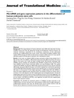
Figure 1a shows the variation of total reflectance with the
amount of carbon precursor (SUC) of C–SiO
2
samples. The
investigation was done with 6, 9, 11 and 12 g of SUC for a
fixed TEOS: H
2
O ratio of 12:9. The low to high reflectance
transition appears to move towards an apparent limit of
2 lm with increasing amount of SUC.
It is striking that for wavelengths less than 0.8 lm, the
reflectance increased with increasing amount of SUC. It
was expected that an increase in SUC would lead to higher
absorption, and hence lower reflectance, in the UV–VIS
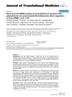
interval. This behaviour suggests that when the amount of
SUC is low the resultant carbon chains in the silica matrix
have on average a small size and more uniform distribu-
tion, as suggested by X-HRTEM image in Fig. 2a, and
therefore would have a higher absorption cross section.
When the amount of SUC was increased the resultant
carbon chains agglomerated to form larger aggregates, as
shown in Fig. 2b, with a large scattering cross section that
resulted in higher reflectance. The gain in absorptance in
the UV–VIS for the low SUC samples was accompanied by
a loss in absorptance in the 0.8–2.0 lm interval due to
resonance absorption by water molecules.
In the near infrared (NIR) and infrared (IR) regions, the
reflectance of the samples with low SUC content is higher
than that of samples with higher SUC content. The reason
for this is that samples of low SUC content were thinner than
those of higher SUC content. This is thought to be purely a
viscosity effect of the sol during the spin-coating process.
The net result of this behaviour is a lower thermal emittance
by samples with low SUC content. It was thus clear that an
optimum of SUC content had to be sought. The optimum for
samples with high absorptance and low emittance was
observed to be 11 g SUC based on the graphs in Fig. 1a.
Characteristic chemical bonds in the C–SiO
2
samples
were identified from the FTIR reflectance spectrum pre-
sented in Fig. 1b. Three distinct absorption bands are
observed. The major band at approximately 1,050 cm
-1
is
assigned to stretching vibrations of Si–O–Si or Si–O–X,
where X represents ethoxy groups bonded to silicon [8, 9].
The shoulder at about 1,200 cm
-1
is assigned to either the
transverse optical mode of the out of phase mode of the
asymmetric vibration or to the longitudinal optical mode of
the high frequency vibration of SiO
2
[8]. On the other side
of the major absorption band, at 900 cm
-1
, is an absorption
band that can be assigned to the stretching vibration of
Si–OH or Si–O
-
groups. A broad absorption band, situated
between 3,000 and 3,600 cm
-1
, and another one around
1,600 cm
-1
are assigned to O–H stretching and O–H
bending vibrations, respectively [8, 9]. The latter
0
0.2
0.4
0.6
0.8
1
101
6 g SUC
9 g SUC
11 g SUC
12 g SUC
R
Wavelength (µm)
0
0.2
0.4
0.6
0.8
1
5001000150020002500300035004000
R
Wavenumber (cm
-1
)
Si - O - Si
OH
OH
Shoulder
(a)
(b)
Fig. 1 a Effect of the amount
of SUC in C–SiO
2
samples spin-
coated at 4,000 rpm and b
identification of chemical bonds
in the absorber composite layer
from an FTIR reflectance
spectrum
422 Nanoscale Res Lett (2008) 3:421–426
123
absorption bands appear to indicate the hydrophilic nature
of the sol–gel synthesized silica.
The reflectance spectra for C–ZnO and C–NiO samples
are presented in Fig. 3a. An attempt has been made to
check reproducibility of the samples of both types by
maintaining the same deposition parameters. In Fig. 3a, the
dips in the spectra between 6 and 7 lm are due to water
absorption (O–H bending vibrations at 1,600 cm
-1
)[6, 9].
The O–H bending vibrations are much weaker than the
case for previously studied C–SiO
2
samples [6]; this
implies a lower emittance for the C–ZnO samples. The
O–H stretching vibrations around 2.7 and 3.3 lm (3,000–
3,600 cm
-1
) of the C–SiO
2
samples (see Fig. 1a) are
clearly absent in the C–ZnO samples resulting in an even
lower emittance (NB: a high reflectance from the sample in
the IR wavelength range means a low emittance by the
sample). The absorption due to the Zn–O vibrations is
expected between 20 and 25 lm[10, 11], which is just
beyond the measurement range for the present work. A
major difference between these spectra and those of pre-
vious experiments on C-SiO
2
selective absorbers [6] is the
absence of strong absorption between 2.5 and 20 lm,
which signifies a great improvement in emittance charac-
teristics of the C–ZnO absorber coatings compared with
those of the previous study of C–SiO
2
selective absorbers.
Another added advantage is that the UV–Vis absorption of
the C–ZnO based samples seems somewhat better than that
of C–SiO
2
. However, a drawback of the C–ZnO based
absorber surfaces is that the transition step from low to
high reflectance is not steep enough for all samples
investigated.
The reflectance spectra of the C–NiO samples are pre-
sented in Fig. 3b. It is clear that both modes of the O–H
vibrations of the C–ZnO samples are absent in the C–NiO
samples; this yields even better emittance characteristics.
The step transition for all the samples is between 2 and
3 lm and is steeper than that of the C–ZnO samples. This
gives the C–NiO samples the closest to a step transition at
2.5 lm expected for an ideal selective solar absorber sur-
face for domestic water heating.
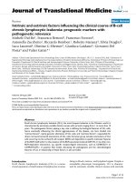
The selected area electron diffraction (SAED) result
shown in Fig. 4a also demonstrated that in most regions,
the coating consisted of nanocrystalline NiO. The electron
diffraction reveals that there exists a small amount of Ni
grains with diameter of about 30 nm in some regions of the
film (see Fig. 4b).
Raman Spectroscopy
The Raman spectroscopy data of the samples were first
analysed using the Tuinstra–Koenig (TK) equation. The
background to this equation, which is important for Raman
spectroscopy characterization of carbon allotropes, is given
in a review article by Gouadec and Colomban [12]. This
equation relates the ratio of phonon intensities of the dis-
order (defect), I
D,
and the prefect graphite peak, I
G
, to the
carbon allotrope grain size. The empirically calibrated TK
equation is given as:
Fig. 2 X-HRTEM images of
samples with a TEOS only and
b Ac
2
O additive
101
0.0
0.2
0.4
0.6
0.8
1.0
Reflectance
Wavelen
g
th (
µ
m)
C-ZnO (sample 1)
C-ZnO (sample 2)
C-ZnO (sample 3)
(a)
101
0.0
0.2
0.4
0.6
0.8
1.0
Reflectance
Wavelen
g
th (
µ
m)
C-NiO (sample 1)
C.NiO (sample 2)
C-NiO (sample 3)
(b)
Fig. 3 The near normal
reflectance spectra of a C–ZnO
samples showing a not-so-steep
transition from low to high
reflectance at about 2.0 lm and
b CNiO samples showing a
steep transition from low to high
reflectance at about 2.5 lm
Nanoscale Res Lett (2008) 3:421–426 423
123
I
Dð1350cm
À1
Þ
I
Gð1580cm
À1
Þ
¼
CðkÞ
L
grain
Cðk ¼ 514:5nmÞ¼44nm ð1Þ
In our samples, the D peaks are weaker than the G peaks
and this suggests that the grain sizes could be larger than
44 nm [12]. From the peak positions x
D
and x
G
and
intensities I
D
and I
G
of the D and G-peaks, respectively, we
calculated the shifts Dx
D
and Dx
G
, ratio I
D
/I
G
, and hence
the grain sizes L
grain
and these are presented in Table 1. (It
must be noted that grain size is different from the size of
the crystallites that agglomerate to form the grain.)
From the calculations, it was found that in all samples,
the D and G-peaks shift in position to higher Raman shift.
The reason for this ‘‘blue shift’’ is due to compressive
stress on the carbon allotrope caused by the matrix. Tensile
stress leads to red-shift as shown in the following relation
between the observed peak position x
vib
and the strain e
lb
of the carbon–carbon bond of length l
b
given by [12]:
x
vib
¼ x
0
1 À
a þr þ3
2
:e
lb
!
ð2Þ
Here x
0
if the peak position for the strain-free bulk
sample. The symbols a and r are, respectively, attractive
and repulsive exponents in the Mie-Grunsen potentials in
solids that govern the bond energies as a function of
interatomic distances. (The values for a and r are
respectively 6 and 12 for van der Waal’s forces in the
6–12 Lennard-Jones potential, 1 and 9 for ionic bonding
and a ? r = 3 for covalent bonding.) It can be clearly seen
that a positive strain (tensile strain) reduces the observed
peak x
vib
leading to a red shift whereas a negative strain
(compressive strain) leads to the opposite effect in peak
position shift—a blue shift. This means that in all samples,
carbon clusters are compressively strained by their
respective host materials as expected.
Phonon confinement models have been used to fit the
asymmetrical broadening of the Raman peaks. We assume
that the carbon clusters and nanocrystallites are perfect
spheres. In this case, we can fit to the Raman spectral data
the following Richter et al. (1981) [13] equation for
asymmetrical Raman line-shapes due to phonon confine-
ment in nanomaterials given as:
IðxÞ¼A
0
Z
1
0
exp À
d
2
q
2
a
x ÀxðqÞ½
2
þ
C
2
0
4
d
3
q ð3Þ
In this equation, A
0
is a pre-factor to be determined from
the fitting session, d is the carbon cluster size, q is the wave
Fig. 4 a A TEM image
together with the corresponding
SAED pattern of a C–NiO
sample and b some Ni grains in
the C–NiO sample. The inset is
the corresponding SAED
pattern
Table 1 Calculations of Raman shifts and grain size estimations for the C–SiO
2
, C–ZnO and C–NiO samples
Sample x
D
(cm
-1
) x
G
(cm
-1
) I
D
I
G
xD
D
(cm
-1
) xD
G
(cm
-1
) I
D
/I
G
L
grain
(nm)
Carbon 1,350 1,580
C–SiO
2
1,384.9 1,603.64 29,144.7 37,241.6 34.9 23.64 0.78,258 56.2
C–ZnO 1,362.6 1,594.3 2,207.96 2,923.4 12.6 14.3 0.75527 58.3
C–NiO 1,358.9 1,594.3 1,435.87 2,009.8 8.9 14.3 0.71443 61.6
424 Nanoscale Res Lett (2008) 3:421–426
123
vector of the exciting light source in the Raman
spectroscopy set-up, a is the scaling factor, x(q) is the
phonon dispersion relation for the material under study and
C
0
is the full width at half maximum of the Raman line-
shape for bulk form of the same material. For materials of
different shapes, a modification of the d
3
q is required. For
instance, d
3
q becomes 2pqdq for nanorods [14] and
proportional to q
2
dq for quantum dots [15].
The typical Raman spectroscopy plots are presented in
Figs. 5–7 for vibrational properties of carbon in SiO
2
, ZnO
and NiO, respectively. No significant asymmetry was
observed in the D peak in all samples. This means that the
size of the defect in these carbon clusters is large. How-
ever, asymmetry in the G peak was observed in all samples
indicating that the nano-carbon is graphitic in structure.
In Figs. 5–7, we have re-drawn the G peak in a separate
graph in order to demonstrate this asymmetry. The Richter
equation was fitted to the experimental data and the rele-
vant parameters in this equation were extracted. The results
for C–NiO and C–ZnO samples are similar except that
intensity is higher in ZnO than NiO. It is interesting to note
that the C–SiO
2
sample shows completely different results:
extremely high scattering intensity and an increasing
background intensity as the Raman shift increases. Due to
the increasing background intensity, the phonon confine-
ment model could not be used for the C–SiO
2
samples.
Typical parameters for the best C–NiO sample are tabu-
lated in Table 2. It can be seen that the crystallite size that
is responsible for the observed asymmetry in the Raman
spectral line-shape for carbon in NiO is 6 nm.
Conclusions and Comments
We have been able to study C–SiO
2
, C–ZnO and C–NiO
selective solar absorber materials using FTIR and Raman
Fig. 5 Raman spectroscopy on difference spots of the C–SiO
2
sample. The G peak has been re-drawn to show the increasing
background noise especially at high scattering intensities
Fig. 6 Raman spectroscopy on difference spots of the C–ZnO
sample. The G peak has been re-drawn to show the asymmetry
which is an indication of the phonon confinement in nanoclusters of
carbon within the ZnO matrix
Nanoscale Res Lett (2008) 3:421–426 425
123
spectroscopy techniques. The thermal emittances of the
samples were 10% for C–SiO
2
, 6% for the C–ZnO and 4%
for the C–NiO samples. The solar absorptances were 95%,
71% and 84% for the C–SiO
2
, C–ZnO and C–NiO samples,
respectively. Based on these results, C–NiO samples
proved to have the best solar selectivity behaviour followed
by the C–ZnO, and last were the C–SiO
2
samples.
The Raman analysis of the selective solar absorber
samples has shown that carbon behaves differently when
placed in matrices of SiO
2
, ZnO and NiO. In all matrices,
the D-band is broad but has no significant asymmetry. The
G-band is indeed asymmetrically broadened in all cases.
The ratio of the intensities of these phonon peaks yields the
following grain sizes for the carbon clusters in the matri-
ces, respectively: 56.2 nm, 58.3 nm and 61.6 nm. The
difference in the grain sizes may be said to be insignificant.
Using the phonon confinement model of Richter [13] yields
a crystallite size of 6 nm which is responsible for the
asymmetrical broadening for both the C–NiO and C–ZnO
samples. The C–NiO samples have the least scattering
intensity of the three. The highest scattering was observed
in C–SiO
2
samples. It was not possible to analyse the
C–SiO
2
samples due to the rising background intensity as
the Raman shift increased.
Acknowledgements Rudolf Erasmus of Witwatersrand University,
South Africa, kindly assisted with the Raman experiments. The CSIR-
National Laser Centre provided financial assistance.
References
1. X. Niu, W. Zhang, E. Zhang, J. Sun, G. Lu, J. Cryst. Growth 263,
167 (2004)
2. S.L. Howell, K.C. Gordon, J. Raman Spectrosc. 39, 813 (2008)
3. F. Froment, A. Tournie, P. Colomban, J. Raman Spectrosc. 39,
560 (2008)
4. R.L. Frost, J. Cejka, M.J. Dickfos, J. Raman Spectrosc. 39, 779
(2008)
5. M.D. Hargreaves, K. Page, T. Munshi, R. Tomset, G. Lynch,
H.G.M. Edwards, J. Raman Spectrosc. 39, 873 (2008)
6. G. Katumba, J. Lu, L. Olumekor, G. Westin, E. Wa
¨
ckelga
˚
rd, J.
Sol–Gel Sci. Technol. 36, 33 (2005)
7. G. Katumba, L. Olumekor, A. Forbes, G. Makiwa, B. Mwaki-
kunga, J. Lu, E. Wackelgard, Sol. Energ. Mater. Sol. C. 92, 1285
(2008)
8. W. Que, Y. Zhou, Y.L. Lam, Y.C. Chan, C.H. Kam, Thin Solid
Films 358, 16 (2000)
9. A.V. Rao, R.R. Kalesh, G.M. Pajonk, J. Mater. Sci. 38, 4407
(2003)
10. X W. Du, Y S. Fu, J. Sun, X. Han, J. Liu, Semicond. Sci. 21,
1202 (2006)
11. M. Matsumura, Z. Bandic, R.P. Camata, Mater. Res. Soc. Symp.
Proc. 869, D1.7.1 (2005)
12. G. Gouadec, Ph. Colomban, Prog. Cryst. Growth Charact. Mater.
53, 1 (2007)
13. H. Richter, Z.P. Wang, L. Ley, Solid State Commun. 39, 625
(1981)
14. B.W. Mwakikunga, E. Sideras-Haddad, A. Forbes, C. Arendse,
Phys. Stat. Sol. (a) 205, 150 (2008)
15. S. Piscanec, M. Cantoro, A.C. Ferrari, J.A. Zapien, Y. Lifshift,
S.T. Lee, S. Hoffmann, J. Robertson, Phys. Rev. B68, 241312(R)
(2003)
Fig. 7 Raman spectroscopy on difference spots of the C–NiO
sample. The G peak has been re-drawn to show that the carbon
clusters are nanostructures as indicated from the asymmetry of this
peak
Table 2 Values extracted from the Richter equation fitting of the
C–ZnO and C–NiO samples
Parameters in phonon confinement model Extracted values
FWHM (bulk ? broadening) 80 cm
-1
Scale parameter 0.081
Crystallite size 6 nm
Pre-factor A
0
7/8,000
Background noise in intensity 1,000
Lattice parameter a
0
in graphite 0.25 nm
Dispersion constant 14 cm
-2
426 Nanoscale Res Lett (2008) 3:421–426
123