Báo cáo hóa học: " The Effect of Interface Texture on Exchange Biasing in Ni80Fe20/Ir20Mn80 Syste" potx
Bạn đang xem bản rút gọn của tài liệu. Xem và tải ngay bản đầy đủ của tài liệu tại đây (350.75 KB, 4 trang )
NANO EXPRESS
The Effect of Interface Texture on Exchange Biasing
in Ni
80
Fe
20
/Ir
20
Mn
80
System
Yuan-Tsung Chen
Received: 23 July 2008 / Accepted: 11 November 2008 / Published online: 25 November 2008
Ó to the authors 2008
Abstract Exchange-biasing phenomenon can induce an
evident unidirectional hysteresis loop shift by spin cou-
pling effect in the ferromagnetic (FM)/antiferromagnetic
(AFM) interface which can be applied in magnetoresis-
tance random access memory (MRAM) and recording-head
applications. However, magnetic properties are the most
important to AFM texturing. In this work, top-configura-
tion exchange-biasing NiFe/IrMn(x A
˚
) systems have been
investigated with three different conditions. From the high-
resolution cross-sectional transmission electron micros-
copy (HR X-TEM) and X-ray diffraction results, we
conclude that the IrMn (111) texture plays an important
role in exchange-biasing field (H
ex
) and interfacial
exchange energy (J
k
). H
ex
and J
k
tend to saturate when the
IrMn thickness increases. Moreover, the coercivity (H
c
)
dependence on IrMn thickness is explained based on the
coupling or decoupling effect between the spins of the
NiFe and IrMn layers near the NiFe/IrMn interface. In this
work, the optimal values for H
ex
and J
k
are 115 Oe and
0.062 erg/cm
2
, respectively.
Keywords Exchange biasing Á Texture Á
Coupling or decoupling effect
Introduction
The exchange-biasing phenomenon using the IrMn basing
layer can be applied in magnetoresistance random access
memory (MRAM) and recording-head applications exten-
sively because Ir
20
Mn
80
exhibits great characteristics: high
interfacial exchange energy (J
k
) (or exchange-biasing field
(H
ex
)), low coercivity (H
c
), high blocking temperature
(T
B
), and good thermal stability in device performance
[1–5]. Moreover, the NiFe/IrMn also can be applied in the
high-frequency ferromagnetic resonance (FMR) [6]. In a
ferromagnetic (FM)/antiferromagnetic (AFM) system, the
texturing in the AFM layer can have an important impact
on the magnetic properties of the system. In the past, a
NiO/NiFe system with varied AFM NiO thicknesses was
studied [7]. In this paper, we will show how the magnetic
properties, such as H
ex
, H
c
, and J
k
, of the IrMn/NiFe top-
configuration system may vary as a function of the IrMn
layer thickness (x). It is found that these magnetic prop-
erties are closely related to the degree of the (111) texture
in the IrMn layer [8–10]. H
ex
and J
k
tend to saturate as x
increases beyond 90 A
˚
. H
c
is inversely proportional to x,
which is caused by the spin coupling or decoupling effect
near the NiFe/IrMn interface.
Experiment Details
The top-configuration NiFe/IrMn system was made by DC
magnetron sputtering onto a glass substrate. The deposition
sequences were: glass/Ta(30 A
˚
)/NiFe(50 A
˚
)/IrMn(x A
˚
)/
Ta(100 A
˚
), where x = 15, 30, 60, 90, 110, and 150 A
˚
. For
this system, we have applied three different conditions
during and/or after deposition: (a) the substrate temperature
(T
s
) was kept at room temperature (RT) only; (b) T
s
was at
RT with an in-plane external field (h) = 500 Oe during
deposition; and (c) T
s
= RT, with h during deposition and
post-deposition annealing in the field at T
A
= 250 °C for
1 h, and then field-cooling to RT. The seed Ta layer was
Y T. Chen (&)
Department of Materials Science and Engineering, I-Shou
University, No. 1, Sec. 1, Syuecheng Road, Dashu Township,
Kaohsiung 840, Taiwan, Republic of China
e-mail:
123
Nanoscale Res Lett (2009) 4:90–93
DOI 10.1007/s11671-008-9207-4
used in order to induce a stronger (111) texture in the NiFe
or IrMn layer [3]. The cap Ta layer was used to protect the
IrMn layer from oxidation. The target compositions of the
IrMn and NiFe alloy are 20 at.% Ir, 80 at.% Mn and
80 at.% Ni, 20 at.% Fe, respectively. The typical base
chamber pressure was better than 1 9 10
-7
Torr, and the
Ar working chamber pressure was 5 9 10
-3
Torr.
The degree of the (111) texture of the Ir
20
Mn
80
layer
was characterized by the X-ray diffraction method using a
CuK
a1
line. In order to observe the growth texture and the
interfacial morphology directly, we performed high-reso-
lution cross-sectional transmission electron microscopy
(HR X-TEM). The exchange-biased magnetic hysteresis
loop was measured by a LakeShore Model 7300 vibrating
sample magnetometer (VSM).
Results and Discussion
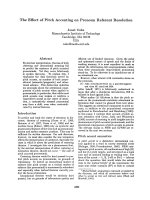
Figure 1 shows a typical unidirectional shifted hysteresis
loop for the top-configuration NiFe(50 A
˚
)/IrMn(90 A
˚
)
sample grown under condition (c). From this figure H
ex
and H
c
are defined: i.e., H
ex
: (H
1
? H
2
)/2 and H
c
:
(H
1
- H
2
)/2. We find that H
ex
= 112 Oe and H
c
= 42 Oe
in this sample.
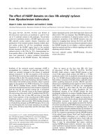
Figure 2 shows the X-TEM images of the three
NiFe(50 A
˚
)/IrMn(90 A
˚
) samples made under three differ-
ent conditions, from (a) to (c), respectively. In Fig. 2a, the
IrMn (111) crystal plane has grown randomly on the
underneath NiFe layer. This indicates that condition (a) is
not sufficient to induce the stronger IrMn texture. Under
condition (b), as shown in Fig. 2b, the (111) texture
arrangement seems better than that in Fig. 2a, but it is still
not the best. In contrast, condition (c) can induce an almost
perfect IrMn (111) texturing, which follows the underlying
NiFe (111) growth texture closely. This clearly indicates
that the (111) texturing can cross the NiFe/IrMn interface
when T
A
is raised to 250 °C. In short, the post-annealing at
elevated T
A
and the deposition field h are necessary con-
ditions to produce the strongest IrMn (111) texture in the
NiFe/IrMn system.
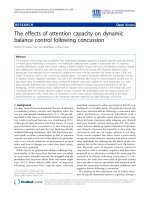
Figure 3 shows different degrees of the IrMn (111)
texture in the NiFe(50 A
˚
)/IrMn(x) system with X-ray dif-
fraction. I
o
is the intensity of the IrMn (111) line and I
b
is
the background intensity. According to this figure, there is
a higher IrMn (111) texture in conditions (b) or (c). As to
condition (a) in Fig. 3, the (111) texture is clearly not well
developed yet. These phenomena are consistent with the
results from X-TEM images.
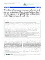
Figure 4 shows H
ex
plotted as a function of the IrMn
thickness (x) for the NiFe(50 A
˚
)/IrMn(x) system under
various conditions. As x B 15 A
˚
, there is almost no
exchange-bias interaction, since J
k
[ K
AF
x, where K
AF
is
the anisotropy energy of IrMn [10]. When x increases from
15 A
˚
to 60 A
˚
, the IrMn pinning action becomes more
effective, or J
k
= K
AF
x, which indicates that H
ex
should
increase with increasing x. Moreover, we find that as
x C 90 A
˚
under conditions (a)–(c), H
ex
tends to saturate.
The last phenomenon is consistent with X-ray and X-TEM
results indicating that the continuation of the (111)
Fig. 1 The hysteresis loop of a glass/Ta(30 A
˚
)/NiFe(50 A
˚
)/
IrMn(90 A
˚
)/Ta(100 A
˚
) sample. This sample was post-annealed at
T
A
= 250 °C and h = 500 Oe for 1 h and then field-cooled to RT.
The switching fields H
1
and H
2
, exchange-biasing field (H
ex
), and
coercivity (H
c
) are indicated in the figure
Fig. 2 The X-TEM images of glass/Ta(30 A
˚
)/NiFe(50 A
˚
)/IrMn
(90 A
˚
)/Ta(100 A
˚
) samples under three different deposition condi-
tions: a deposited at RT only, b deposited at RT with an external field
h = 500 Oe, and c the same film-growth procedure as in (b),
post-annealing at T
A
= 250 °C with h on for 1 h, and then field-
cooling to RT
Nanoscale Res Lett (2009) 4:90–93 91
123
perpendicular texture across the NiFe/IrMn interface
should stop H
ex
from decreasing.
According to the well-known theory based on the
interfacial exchange-biasing phenomenon,
J
k
¼ H
ex
M
s
t
FM
ð1Þ
where M
s
is the saturation magnetization of the NiFe layer.
Since the ferromagnetic thickness t
FM
= 50 A
˚
is fixed for
these NiFe/IrMn systems, M
s
is constant. Therefore, from
Eq. 1, J
k
is proportional to H
ex
. The x dependence of J
k
in
Fig. 5 should look similar to that of H
ex
in Fig. 4. Note that
the largest J
k
value, about 0.062 erg/cm
2
, has been realized
in this study, as shown in Fig. 5. The value is about half of
that found in reference [11].
The H
c
is plotted as a function of x in Fig. 6. In general,
H
c
increases in the x range from 15 A
˚
to 30 A
˚
(or 60 A
˚
)
and decreases in the x range thereafter. According to ref-
erence [12], the H
c
behaviors are caused by the spin
coupling and decoupling effects at the NiFe/IrMn interface
as x increases. As discussed before, when x increases from
30 A
˚
to 60 A
˚
, H
ex
increases gradually, which implies the
NiFe/IrMn coupling drag interaction. In turn, the coupling
force between the NiFe and the nearest IrMn spins at the
Fig. 3 The degree of the IrMn (111) texture, as determined from the
X-ray diffraction studies, is shown as a function of x for glass/
Ta(30 A
˚
)/NiFe(50 A
˚
)/IrMn(x A
˚
)/Ta(100 A
˚
). I
o
is the intensity of the
IrMn (111) line and I
b
is the background intensity
Fig. 4 IrMn thickness (x) dependence of the exchange-biasing field
(H
ex
) for the glass/Ta(30 A
˚
)/NiFe(50 A
˚
)/IrMn(x A
˚
)/Ta(100 A
˚
) sam-
ples under conditions (a)to(c)
Fig. 5 IrMn thickness (x) dependence of the interfacial energy (J
k
)
is shown for the glass/Ta(30 A
˚
)/NiFe(50 A
˚
)/IrMn(x)/Ta(100 A
˚
)
systems
Fig. 6 Coercivity (H
c
) versus the IrMn thickness (x) for the glass/
Ta(30 A
˚
)/NiFe(50 A
˚
)/IrMn (x A
˚
)/Ta(100 A
˚
) systems
92 Nanoscale Res Lett (2009) 4:90–93
123
interface is larger than that between neighboring IrMn
spins. The external field (H) needs to rotate not only the
NiFe spins but also the IrMn spins on top together. As a
result, the resistance to domain wall motion is higher, and
H
c
should increase as x increases from 15 A
˚
to 60 A
˚
.
However, as x continues to increase, H
c
eventually
decreases, due to the decoupling effect between the inter-
facial NiFe spin and the IrMn spin on top. The reason for
the decoupling is that as x continues to increase, H
ex
is
fully developed, and even the lowest-level IrMn spin (at
the interface) is strongly pinned by the IrMn spins above.
Therefore, when the external field is large enough to switch
the NiFe spin at H = H
c
, the neighboring IrMn spin does
not rotate together anymore. Hence, H
c
decreases as
x C 60 A
˚
(Fig. 6).
Conclusions
In conclusion, under the various conditions (a)–(c) for the
top-configuration NiFe/IrMn systems, the magnetic prop-
erties, such as H
ex
, J
k
, and H
c
, have been investigated.
These magnetic properties are closely related to the growth
IrMn (111) texturing. From HR X-TEM and X-ray dif-
fraction results, we conclude that the strongest IrMn (111)
texture appears in condition (c). Therefore, condition (c)
should induce the highest H
ex
and J
k
. Furthermore, the H
c
value first increases and then decreases as x increases from
15 A
˚
to 150 A
˚
. This is due to the spin coupling and
decoupling drag effects at the NiFe/IrMn interfaces. The
optimal H
ex
and J
k
values obtained from this study are
115 Oe and 0.062 erg/cm
2
, respectively. This H
ex
value of
NiFe/IrMn is larger or equal to the optimal H
ex
in the NiO/
NiFe systems [13, 14].
Acknowledgments This work was supported by the National Sci-
ence Council and I-Shou University, under Grant Nos. (NSC97-2112-
M214-001-MY3), (ISU97-S-03), and (ISU97-02-20).
References
1. C.C.Y. Andrew, X.F. Han, J. Murai, Y. Ando, T. Miyazaki, K.
Hiraga, J. Magn. Magn. Mater. 240, 130 (2002). doi:10.1016/
S0304-8853(01)00734-X
2. D. Lacour, O. Durand, J L. Maurice, H. Jaffre
`
s, F. Nguyen Van
Dau, F. Petroff, P. Etienne, J. Humbert, A. Vaure
`
s, J. Magn.
Magn. Mater. 270, 403 (2004). doi:10.1016/j.jmmm.2003.09.007
3. L. Hua-Rui, R. Tian-Ling, Q. Bin-Jun, L. Li-Tian, K. Wan-Jun,
L. Wei, Thin Solid Films 441, 111 (2003). doi:10.1016/
S0040-6090(03)00952-0
4. J. van Driel, F.R. de Boer, K M.H. Lenssen, R. Coehoorn,
J. Appl. Phys. 88, 975 (2000). doi:10.1063/1.373764
5. S F. Cheng, P. Lubitz, J. Appl. Phys. 87, 4927 (2000). doi:
10.1063/1.373205
6. O. Acher, S. Queste, K U. Barholz, R. Mattheis, J. Appl. Phys.
93, 6668 (2003). doi:10.1063/1.1556098
7. C.H. Lai, H. Matsuyama, R.L. White, T.C. Anthony, G.G. Bush,
J. Appl. Phys. 79, 6389 (1996). doi:10.1063/1.362007
8. P. Wisniowski, T. Stobiecki, J. Kanak, G. Reiss, H. Bruckl,
J. Appl. Phys. 100, 13906 (2006). doi:10.1063/1.2209180
9. A.E. Berkowitz, Kentaro. Takano, J. Magn. Magn. Mater. 200,
552 (1999). doi:10.1016/S0304-8853(99)00453-9
10. G. Malinowski, M. Hehn, S. Robert, O. Lenoble, A. Schuhl,
J. Appl. Phys. 98, 113903 (2005). doi:10.1063/1.2136233
11. Y.T. Chen, S.U. Jen, Y.D. Yao, J.M. Wu, J.H. Liao, T.B. Wu,
J. Alloy. Compd. 448, 59 (2008). doi:10.1016/j.jallcom.2006.
12.099
12. M. Ali, C.H. Marrows, M. Al-Jawad, B.J. Hickey, A. Misra, U.
Nowak, K.D. Usadel, Phys. Rev. B 68, 214420 (2003). doi:
10.1103/PhysRevB.68.214420
13. G.H. Yu, C.L. CHai, H.C. Zhao, F.W. Zhu, J.M. Xiao, J. Magn.
Magn. Mater. 224, 61 (2001). doi:10.1016/S0304-8853(00)
01337-8
14. D.G. Huang, C.M. Park, S.S. Lee, J. Magn. Magn. Mater. 186,
265 (1998). doi:10.1016/S0304-8853(98)00089-4
Nanoscale Res Lett (2009) 4:90–93 93
123