Báo cáo hóa học: " Multi-Stable Conductance States in Metallic Double-Walled Carbon Nanotubes" ppt
Bạn đang xem bản rút gọn của tài liệu. Xem và tải ngay bản đầy đủ của tài liệu tại đây (435.33 KB, 6 trang )
NANO EXPRESS
Multi-Stable Conductance States in Metallic Double-Walled
Carbon Nanotubes
Dongsheng Tang Æ Yong Wang Æ Huajun Yuan Æ
Lijie Ci Æ Weiya Zhou Æ Sishen Xie
Received: 2 December 2008 / Accepted: 9 February 2009 / Published online: 27 February 2009
Ó to the authors 2009
Abstract Electrical transport properties of individual
metallic double-walled carbon nanotubes (DWCNTs) were
measured down to liquid helium temperature, and multi-
stable conductance states were found in DWCNTs. At a
certain temperature, DWCNTs can switch continuously
between two or more electronic states, but below certain
temperature, DWCNTs are stable only at one of them. The
temperature for switching is always different from tube to
tube, and even different from thermal cycle to cycle for the
same tube. In addition to thermal activation, gate voltage
scanning can also realize such switching among different
electronic states. The multi-stable conductance states in
metallic DWCNTs can be attributed to different Fermi
level or occasional scattering centers induced by different
configurations between their inner and outer tubes.
Keywords Carbon nanotube Á Electrical transport
property Á Intertube interaction
Introduction
It is well established that the electrical properties of carbon
nanotubes (CNTs) are sensitive to their nanostructures such
as diameters, chiralities, defects, etc. [1–5]. In fact, CNTs
prefer to be assembled as ropes by close-packing or as multi-
walled CNTs (MWCNTs) by arranging them concentrically
[6]. In both cases, interactions among nanotubes may sig-
nificantly modify their electronic structures, and then
introduce interesting variations in their electrical properties.
For example, in the case of ropes of identical armchair sin-
gle-walled CNTs (SWCNTs) intertube interactions can
break their rotational symmetry, and then the p* and p bands
can mix, which will produce a pseudogap about 0.1 eV at the
Fermi level [7–9]. As for MWCNTs, the case is a little more
complicated because each one of these tubes has different
diameters and can have different chiralities.
To explore the effect of the intertube interactions on
electrical properties of MWCNTs, double-walled CNTs
(DWCNTs) is the best candidate because they are the sim-
plest MWCNTs to be dealt theoretically, which consist of
only two tubes having the similar diameters as SWCNTs. In
fact, most of the theoretical work on electronic structures of
MWCNTs has been done based on DWCNTs [10–17].
Sanvito et al. [14] found that the interwall interactions may
block some quantum conductance channels by investigating
the electron transport properties of the commensurate
DWCNTs. Roach et al. [15] inferred that the electronic
propagation may follow a non-ballistic law based on the
spreading properties of the wave packets in the incom-
mensurate DWCNTs. Kwon and Toma
´
nek [16] found that
the weak interwall interactions and changing symmetry can
cause four pseudogaps to open and close periodically near
the Fermi level during the soft librational motion. Recently,
much experimental work has been specifically focused on
this issue [17–21]. Kajiura et al. [17] demonstrated that the
electrons pass through DWCNTs quasi-ballistically even at
room temperature. Wang et al. [18] found that free charges
in the inner metallic wall may screen the outer semicon-
ducting wall from the gate effect. Moon et al. [20]
D. Tang (&) Á Y. Wang Á H. Yuan
Key Laboratory of Low-Dimensional Quantum Structures and
Quantum Control of Ministry of Education, College of Physics
and Information Science, Hunan Normal University,
Changsha 410081, China
e-mail: ;
L. Ci Á W. Zhou Á S. Xie
Institute of Physics, Chinese Academy of Sciences,
Beijing 100080, China
123
Nanoscale Res Lett (2009) 4:538–543
DOI 10.1007/s11671-009-9277-y
determined the current-carrying capacity of each wall of
DWCNTs by breaking down their wall sequentially under
high bias voltages.
In this paper, we present electrical transport properties of
individual metallic DWCNTs with highly transparent
contacts. We found that conductance state of DWCNTs is
multi-stable at low temperature. At a certain temperature,
DWCNTs can switch between two or more electronic states,
but below a certain temperature, DWCNTs is stable only at
one of them. The temperature for switching is always dif-
ferent from tube to tube, and even different from thermal
cycle to cycle for the same tube. In addition to thermal
activation, gate voltage scanning can also realize such
switching among different electronic states. This electrical
behavior of DWCNTs is like the two level fluctuations or
random telegraph signals observed in tunnel junctions,
metal-oxide-semiconductor field-effect transistors (MOS-
FETs), and FETs based on p-type semiconducting SWCNTs.
It can be attributed to different configurations or small
movement between their inner and outer tubes under the
equilibrium of the van der Waals interaction between layers
with the elastic force of the graphene layers, which can affect
the electronic structures of DWCNTs by shifting the Fermi
level or inducing occasional electron scattering centers.
Experimental
DWCNTs used in our measurements were synthesized by
pyrolizing C
2
H
2
at a temperature of 900–1100 °Confloating
iron catalysts promoted with sulfur. Diameters of outer tubes
vary from 1.1 to 2.9 nm, and those of inner tubes from 0.4 to
2.2 nm, which was determined by transmission electron
microscopy [22]. DWCNTs were first dispersed in an aqueous
surfactant solution (1 wt% lithium dodecyl sulfate) and puri-
fied by centrifugation. Thereafter they were deposited on a
highly n-doped silicon wafer with 100 nm SiO
2
layer by
putting one droplet of suspension on the surface. Si wafer has
been modified previously by amino-silanization. Electrodes
were defined by using an electron beam lithography procedure
with standard two-layer resist, and formed by evaporating
15 nm AuPd. Devices containing individual metallic
DWCNTs with good source and drain contacts were selected
for electrical transport measurements. The DWCNT between
two electrodes is 150-nm long. The n-doped Si wafer was used
asthebackgate.Theelectricaltransportmeasurementswere
carried out in a cryostat with a lock-in technique.
Results and Discussion
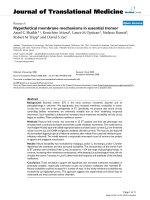
The most important feature of our DWCNT devices is
that there are multi-stable conductance states at low
temperature. As shown by the linear conductance versus
temperature (G–T) curve of a metallic DWCNT (sample
No. 1) (inset of Fig. 1), the linear conductance fluctuates
unconventionally around 10 K, which looks like noises or
fluctuations. However, they locate almost on the same
level. By sweeping the bias voltage (V
D
) continuously at
around 10 K on this DWCNT immediately, we obtained
four typical current versus V
D
(I–V
D
) curves, as indicated
in Fig. 1. This indicates that this DWCNT seems to have
different linear conductance for different V
D
sweeping
cycles under almost the same conditions (temperature
fluctuations less than 0.05 K). It even can switch or fluc-
tuate continuously between two levels in the same
sweeping cycle, just like the two level fluctuations in
tunnel junctions, MOSFETs, and FETs based on p-type
semiconducting SWCNTs reported previously [23–25]. It
seems that there are two electronic states in this DWCNT,
and the DWCNT can stay stable at the low conductance
state, the high conductance state, mixed state of them, and
can even switch continuously between them. It also sug-
gests that the mechanism for this kind of switching might
be a slow process compared with the time scale of
measurement.
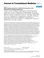
As a matter of fact, the I–V
D
curves are always
non-linear. Figure 2 shows an I–V
D
curve (inset) and the
corresponding dI/dV–V
D
curve (simultaneously recorded
by the lock-in technique) of another metallic DWCNT
(sample No. 2) in a large bias range. It indicates the same
phenomenon as described above. Besides the difference in
linear conductance around zero bias, another important
feature of those two states is the difference in non-linearity
indicated by the dI/dV–V
D
curve. For the low conductance
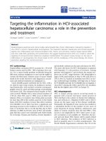
Fig. 1 Different I–V
D
curves of a metallic DWCNT recorded around
9.9 K continuously indicate that there are multi-stable conductance
states in this tube. Inset: Linear conductance of the DWCNT as a
function of temperature from 300 to 2 K on a double logarithmic
scale
Nanoscale Res Lett (2009) 4:538–543 539
123
state, there is a dip; while for the high conductance state,
there is a peak around zero bias. Furthermore, this dI/dV
peak around zero bias does not respond to magnetic field as
high as 10 Tesla.
Almost all our DWCNT samples exhibit sporadic
changes in conductance, but only at a certain temperature,
could the continuous switch between two or more levels be
observed by careful measurements. After all, this kind of
switching is sensitive to temperature, and can disappear
even under temperature fluctuations less than 0.05 K. On
the other hand, the temperature for conductance switching
is different from tube to tube, even different from thermal
cycle to cycle on the same tube. We have observed this
kind of continuous switching on four different DWCNTs at
2.1, 4.9, 9.9, and even at 49.7 K, respectively.
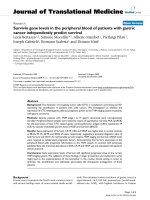
In order to get more information about the different
electronic states in DWCNTs, we have measured another
metallic DWCNT (sample No. 3) very carefully. We
recorded G–T curve when this DWCNT was cooled down,
and dI/dV–V
D
curves at different temperature when
warmed up step by step. As shown in the inset of Fig. 3a,
the conductance behaves completely different as tempera-
ture is cooled down in different thermal cycles: decreases
in the first cooling process (black curve), but increases in
the second one (after warming up from 2 to 130 K) and the
third one (after warming up from 2 to 50 K) (red and green
curves). Below 50 K, the G–T curves recorded in the
second and third thermal cycles coincide with each other
completely, which means that this tube is electrically stable
during this measurement. Over 50–300 K, the G–T curves
recorded in the first and second thermal cycles coincide
with each other, and there is little change in conductance
for both cases, which means that there is very low proba-
bility of electron–phonon scattering in this DWCNT, and
the factor for the different conductance states in the
DWCNTs might be smeared by thermal activation. The
corresponding dI/dV–V curves (Fig. 3a) indicate that
around zero bias there is a peak for high conductance state
Fig. 2 The dI/dV–V
D
and I–V
D
(inset) curves recorded at the same
time for another metallic DWCNT. The arrows indicate the sweeping
directions
Fig. 3 a G–T curves of a metallic DWCNT recorded three times
continuously when cooling down (Inset) and dI/dV–V
D
curves recorded
at various temperatures for the high conductance state (upside) and the
low conductance state (downside) when heating up step by step. b The
evolution of the dI/dV peaks around zero bias under small gate voltage
(-0.1 to 0.1 V, step size: 0.01 V, curves shifted for clarity). c Two-
dimensional dI/dV plot as a function of V
D
and V
G
540 Nanoscale Res Lett (2009) 4:538–543
123
and a dip for low conductance state. As the temperature is
lowered, the structures in dI/dV–V
D
curve become sharper,
i.e., the peak increases, while the dip decreases in con-
ductance, but both saturate below 5 K, which is consistent
with the G–T curves.
The evolution of the dI/dV peak around zero bias under
small gate voltage (V
G
) was shown in Fig. 3b, which indi-
cates that this peak shifts and evolves into a dip with V
G
.This
process is completely reversible. In fact, the curve modulated
by gate voltage (V
G
= 0.1 V) is almost the same as the low
conductance state curve in the downside of Fig. 3a, which
indicates that V
G
can realize switching between these two
conductance states and may suggest different Fermi level
positions for these two states. From the two-dimensional
dI/dV plots (Fig. 3c, 5a) we can make a rough estimate of the
capacitance between the DWCNT and the back gate:
C
G
= 4eC/V, where e is the charge of an electron. The
excess charge Q on the DWCNT induced by V
G
can be
obtained as Q = C
G
V
G
= 4e*0.1 = 0.4eC. Therefore, the
different conductance states might be attributed to charges
trapping in or escaping from impurities, defects on the
DWCNT, or insulating layer adjacent to this tube.
As the case stands, our devices can be definitely switched
to a relative high conductance state by positive V
G
pulse
(15 V), and a low conductance state by negative V
G
pulse at
high temperature (for example [72 K) (Fig. 4a). This is
similar to the electrical hysteresis observed in semicon-
ducting SWCNTs, and it is believed to be induced by the
charges trapped in impurities or defects [26–28]. As the
temperature is lowered, the electrical hysteresis weakens
and fades away gradually, which means that the charges
trapped in impurities or defects become fewer and fewer.
When the temperature is lower than 72 K, the DWCNT
becomes electrically unstable after V
G
sweeping, and the
change in conductance is random and unpredictable. Fur-
thermore, the lower the temperature is, the larger the change
in conductance is. That is to say, at low temperature, the V
G
pulse cannot change the electronic state directly by trapping
charges in impurities or defects. However, it disturbs the
electronic state of DWCNTs in its own way. Figure 4b
shows all kind of dI/dV–V
D
curves recorded repeatedly on
the DWCNT after being disturbed by a positive V
G
pulse at
2.280 K. It indicates that this DWCNT switches among
different electronic states indeed. Around zero bias, there
can be a peak or a dip corresponding to different electronic
states just as shown in Fig. 2.
Our individual metallic DWCNT devices have good
source and drain contacts. They are much different from
the tunnel junctions and MOSFETs that exhibit two level
conductance fluctuations [23, 24], and also different from
the semiconducting SWCNT-based FETs that exhibit ran-
dom telegraph noise at high temperature (200 K, for
example) and stable electrical hysteresis at low temperature
(5 K) [24, 28]. After all the non-localized electrons trans-
port ballistically through the tubes (to be discussed later),
the density of impurities or defects in our DWCNTs is very
low. Other than charges trapped in impurities or defects,
there might be a new mechanism that bring on the multi-
stable electronic states, and can be disturbed by the V
G
and
thermal activation.
The two-dimensional dI/dV plot as a function of V
D
and
V
G
for the sample No. 3 (Fig. 3c) indicates that the posi-
tions of the dI/dV dips and peaks evolve smoothly and
periodically pointing to a Fabry–Perot interference pattern,
which means that the peaks and dips of dI/dV curve come
Fig. 4 a Linear conductance of a metallic DWCNT (sample No. 2) as
a function of time, recorded under periodic V
G
pulse at different
temperature (curves shifted for clarity), which shows that the
DWCNT exhibits electrical hysteresis behavior at high temperature
([72.39 K) and is electrically unstable at low temperature
(\72.39 K). b The dI/dV curves of the DWCNT recorded repeatedly
after being disturbed by a positive V
G
pulse (15 V) at 2.280 K in
another thermal cycle
Nanoscale Res Lett (2009) 4:538–543 541
123
from quantum interference between the propagating elec-
tron waves [29]. On the other hand, this pattern is
somewhat irregular, having different periodicities in dif-
ferent parts and being asymmetric with V
D
, which points to
a non-ideal Fabry–Perot interference pattern due to minor
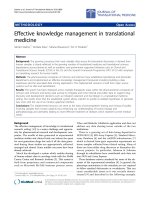
disorder or inhomogeneity along this tube. Figure 5a shows
a two-dimensional dI/dV plot as a function of V
D
and V
G
for another DWCNT (sample No. 4, d = 2.5 nm and
L = 150 nm). It consists of two patterns with distinct
boundary at V
G
= 3.70 V. On the left side, the regular
interference pattern means a perfect Fabry–Perot resonator
with an interference peak at V
D
= V
C
= ht
F
/2eL =
11.1 mV (t
F
= 8.1 9 10
5
m/s is the Fermi velocity and
L = 150 nm is the length of tube). It indicates that electron
scattering occurs mostly at the nanotube–electrode inter-
face and electrons pass through the nanotube ballistically.
On the other hand, firstly the conductance decreases sud-
denly overall (also see Fig. 5b); secondly the V
D
and V
G
spacing between adjacent peaks (dips) increases (about two
times); thirdly the dI/dV curves become asymmetric. All of
these point to a fact that there is a disorder which serves
as a new electron-backscattering center (V
0
D
¼ V
0
C
¼
ht
F
=2eL
0
¼ 22:2mV; then L
0
¼ 75 nm) appearing in the
middle of the tube, and that the tube has been hole doped
by the new mechanism. When measured in another thermal
cycle, this kind of electron-backscattering center disap-
peared, and regular Fabry–Perot interference pattern will
appear again in all the V
G
sweeping range (0–20 V). It
means that the appearance or disappearance of this kind of
electron-backscattering center is reversible, and V
G
is not
the sufficient condition to activate this kind of disorder, and
that there is no or few impurities or defects in our
DWCNTs. This kind of disorder can be observed again, but
only by chance. By carefully checking Fig. 5b, we found
out that the abrupt change in dI/dV consists of two parts:
decrease in the overall conductance and dI/dV peaks
shifting versus V
D
. The former might be due to the
appearance of electron scattering center, and the latter
might be due to the shift of Fermi level induced by charge
accumulation. In our measurements on DWCNTs, these
two kinds of change have been observed independently or
synchronously.
The electrical transport properties of DWCNTs charac-
terized by multi-stable conductance states might originate
from their larruping microstructures: small diameter and
two layers. It is said that the weak interwall interactions can
activate low-frequency librational motion about and vibra-
tion motion normal to the tube axis for the inner tube in
DWCNTs [16]. It may be hard to believe that the entire inner
tube vibrate or librate; however, it is possible for some small
part of the twisted inner tube to vibrate or librate indepen-
dently under the equilibrium of the van der Waals
interaction between layers with the elastic force of the
graphene layers. There may be orientational dislocations or
twist frozen in DWCNTs during their synthesis. High res-
olution transmission electron microscopy (HR-TEM)
observation revealed that there are smaller (0.39 nm)
interlayer spaces with the commensurate lattice and larger
(0.54 nm) spaces also in the same DWCNT [30]. Calcula-
tions also indicated that the interwall interactions can induce
electron transfer from outer tube to interwall region, and
then the outer tube can be viewed as being hole doped by the
inner tube [31]. When the inner tube (or part of it) changes
its configuration about the tube axis sporadically, the
amount of charge transfer will change accordingly, and then
the Fermi level will shift. We believe that the V
G
can disturb
the charge distribution in the interwall region, and then the
configuration of DWCNTs. When the inner tube vibrates
normal to the tube axis, the inner tube is close to the outer
tube on one side and far away on the other side, which will
serve as the new factor for electron scattering [32].
Therefore, we consider that the multi-stable conduc-
tance states in DWCNTs can be attributed to the different
Fig. 5 a Two-dimensional dI/dV plot as a function of V
D
and V
G
measured at 5.0 K for a metallic DWCNT. b The dI/dV–V
D
curves
around the distinct boundary of the two-dimensional dI/dV plot as
shown in (a)
542 Nanoscale Res Lett (2009) 4:538–543
123
configurations of its outer and inner tubes. The continu-
ously switching between two electronic states can be
attributed to the locally orientational depinning or melting
of a small part of inner tube at certain temperature (T
OM
,
9.9 K for sample No. 1). When the temperature is lower
than T
OM
, the two tubes are pinned and the vibration of
inner tube is small, and then the DWCNT is electronically
stable at different states due to the different configurations.
At relatively high temperature ([T
OM
) one or more parts of
inner tube can vibrate freely and independently. All states
from different configurations can contribute to the electri-
cal properties at the same time, and then the DWCNT is
also stable at a mixed state. When just at T
OM
, one part of
the inner tube can switch continuously and slowly under
the equilibrium of the van der Waals interaction between
layers with the elastic force of the graphene layers, and so
does the conductance. Because the orientational disorder is
different from tube to tube, even different from thermal
cycle to cycle on the same tube; the temperature for ori-
entational melting T
OM
is also different from tube to tube.
Conclusions
We have observed multi-stable conductance states in
DWCNTs at liquid helium temperature. At a certain tem-
perature, DWCNTs can switch continuously between two
or even more electronic states. Below certain temperature,
DWCNTs can be stable at different electronic states due to
different Fermi level or occasional scattering centers
induced by different configurations between their inner and
outer tubes. The temperature for switching is always dif-
ferent from tube to tube, and even different from thermal
cycle to cycle for the same tube. This electrical behavior
might shed light on the effect of inter-walled interactions
on the electrical transport properties of MWCNTs.
Acknowledgments This work was supported by the Major Research
plan of National Natural Science Foundation of China (Grant No.
90606010), the Program for New Century Excellent Talents in Uni-
versity (Grant No. NCET-07-0278) and the Hunan Provincial Natural
Science Fund of China (Grant No. 08JJ1001).
References
1. N. Hamada, S.I. Sawada, A. Oshiyama, Phys. Rev. Lett. 68, 1579
(1992). doi:10.1103/PhysRevLett.68.1579
2. C.T. White, T.N. Todorov, Nature 393, 240 (1998). doi:10.1038/
30420
3. C.L. Kane, E.J. Mele, Phys. Rev. Lett. 78, 1932 (1997). doi:
10.1103/PhysRevLett.78.1932
4. S.J. Tans, A.R.M. Verschueren, C. Dekker, Nature 393,49
(1998). doi:10.1038/29954
5. M.K. Ge, K. Sattler, Science 260, 515 (1993). doi:10.1126/
science.260.5107.515
6. A. Thess, R. Lee, P. Nikolave, H. Dai, P. Petit, J. Robert, C. Xu,
Y.H. Lee, S.G. Kim, A.G. Rinzler, D.T. Colbert, G.E. Scuseria,
D. Toma
´
nek, J.E. Fisher, R.E. Smalley, Science 273, 483 (1996).
doi:10.1126/science.273.5274.483
7. P. Delaney, H.J. Choi, J. Ihm, S.G. Louie, M.L. Cohen, Nature
391, 466 (1998). doi:10.1038/35099
8. Y.K. Kwon, S. Saito, D. Toma
´
nek, Phys. Rev. B 58, R13314
(1998). doi:10.1103/PhysRevB.58.R13314
9. M. Ouyang, J.L. Huang, C.L. Cheung, C.M. Lieber, Science 292,
702 (2001). doi:10.1126/science.1058853
10. L. Langer, V. Bayot, E. Grivei, J.P. Issi, J.P. Heremans, C.H. Olk,
L. Stockman, C. Van Haesendonck, Y. Bruynseraede, Phys. Rev.
Lett. 76, 479 (1996). doi:10.1103/PhysRevLett.76.479
11. A. Bachtold, C. Strunk, J.P. Salvetat, J.M. Bonard, L. Forro
´
,
T. Nussbaumer, Nature 397, 673 (1999). doi:10.1038/17755
12. C. Scho
¨
nenberger, A. Bachtold, C. Strunk, J.P. Salvetat, L. Forro
´
,
Appl. Phys. A 69, 283 (1999)
13. A. Latge
´
,D.Grimm,Carbon45, 1905 (2007). doi:10.1016/j.carbon.
2007.04.019
14. S. Sanvito, Y.K. Kwon, D. Toma
´
nek, C.J. Lambert, Phys. Rev.
Lett. 84, 1974 (2000). doi:10.1103/PhysRevLett.84.1974
15. S. Roche, F. Triozon, A. Rubio, D. Mayou, Phys. Rev. B 64,
121401-1 (2001). doi:10.1103/PhysRevB.64.121401
16. Y.K. Kwon, D. Toma
´
nek, Phys. Rev. B 58, R16001 (1998). doi:
10.1103/PhysRevB.58.R16001
17. H. Kajiura, H. Huang, A. Bezryadin, Chem. Phys. Lett. 398, 476
(2004). doi:10.1016/j.cplett.2004.09.115
18. S. Wang, X.L. Liang, Q. Chen, Z.Y. Zhang, L.M. Peng, J. Phys.
Chem. B
109, 17361 (2005). doi:10.1021/jp053739?
19. D.S. Tang, L.J. Ci, W.Y. Zhou, S.S. Xie, Carbon 44, 2155 (2006).
doi:10.1016/j.carbon.2006.03.023
20. S. Moon, W. Song, N. Kim, J. Sung Lee, P.S. Na, S.G. Lee,
J. Park, M.H. Jung, H.W. Lee, K. Kang, C.J. Lee, J. Kim,
Nanotechnology 18, 235201 (2007). doi:10.1088/0957-4484/18/
23/235201
21. I. Maeng, C. Kang, S.J. Oh, J.H. Son, K.H. An, Y.H. Lee, Appl.
Phys. Lett. 90, 051914 (2007). doi:10.1063/1.2435338
22. L.J. Ci, Z.L. Rao, Z.P. Zhou, D.S. Tang, X.Q. Yan, Y.X. Liang,
D.F. Liu, H.J. Yuan, W.Y. Zhou, G. Wang, W. Liu, S.S. Xie,
Chem. Phys. Lett. 359, 63 (2002). doi:10.1016/S0009-2614(02)
00600-0
23. X. Jiang, M.A. Dubson, J.C. Garland, Phys. Rev. B 42, 5427
(1990). doi:10.1103/PhysRevB.42.5427
24. K.R. Farmer, C.T. Rogers, R.A. Buhrman, Phys. Rev. Lett. 58,
2255 (1987). doi:10.1103/PhysRevLett.58.2255
25. F. Liu, M.Q. Bao, H.J. Kim, K.L. Wang, C. Li, X.L. Xiao, C.W.
Zhou, Appl. Phys. Lett. 86, 163102-1 (2005). doi:10.1063/
1.1901822
26. J.B. Cui, R. Sordan, M. Burghard, K. Kern, Appl. Phys. Lett. 81,
3260 (2002). doi:10.1063/1.1516633
27. W. Kim, A. Javey, O. Vermesh, Q. Wang, Y. Li, H. Dai, Nano.
Lett. 3, 193 (2003). doi:10.1021/nl0259232
28. B.M. Kim, Y.F. Chen, M.S. Fuhrer, Fullerenes 12, 541 (2002)
29. W. Liang, M. Bockrath, D. Bozovic, J.H. Hafner, M. Tinkham,
H. Park, Nature 411, 665 (2001). doi:10.1038/35079517
30. A. Hashimoto, K. Suenaga, K. Urita, T. Shimada, T. Sugai,
S. Bandow, H. Shinohara, S. Iijima, Phys. Rev. Lett. 94, 045504-1
(2005). doi:10.1103/PhysRevLett.94.045504
31. Y. Miyamoto, S. Saito, D. Toma
´
nek, Phys. Rev. B 65, 041402-1
(2001). doi:10.1103/PhysRevB.65.041402
32. D. Orlikowski, H. Mehrez, J. Taylor, H. Guo, J. Wang, C. Roland,
Phys.Rev.B63, 155412-1 (2001). doi:10.1103/PhysRevB.63.155412
Nanoscale Res Lett (2009) 4:538–543 543
123