Báo cáo hóa học: " Research Article A Chip-Level BSOR-Based Linear GSIC Multiuser Detector for Long-Code CDMA Systems" doc
Bạn đang xem bản rút gọn của tài liệu. Xem và tải ngay bản đầy đủ của tài liệu tại đây (824.27 KB, 9 trang )
Hindawi Publishing Corporation
EURASIP Journal on Wireless Communications and Networking
Volume 2007, Article ID 25945, 9 pages
doi:10.1155/2007/25945
Research Article
A Chip-Level BSOR-Based Linear GSIC Multiuser Detector for
Long-Code CDMA Systems
A. Bentrcia,
1
A. Zerguine,
1
and M. Benyoucef
2
1
Electrical Engineering Department, King Fahd University of Petroleum and Minerals, P.O.Box 1387, Dhahran 31261, Saudi Arabia
2
Department of Electronics, Faculty of Engineering, University of Batna, Batna 05000, Algeria
Received 7 March 2007; Revised 7 August 2007; Accepted 10 October 2007
Recommended by Chia-Chin Chong
We introduce a chip-level linear group-wise successive interference cancellation (GSIC) multiuser structure that is asymptotically
equivalent to block successive over-relaxation (BSOR) iteration, which is known to outperform the conventional block Gauss-
Seidel iteration by an order of magnitude in terms of convergence speed. The main advantage of the proposed scheme is that it
uses directly the spreading codes instead of the cross-correlation matrix and thus does not require the calculation of the cross-
correlation matrix (requires 2NK
2
floating point operations (flops), where N is the processing gain and K is the number of users)
which reduces significantly the overall computational complexity. Thus it is suitable for long-code CDMA systems such as IS-95
and UMTS where the cross-correlation matrix is changing every symbol. We study the convergence behavior of the proposed
scheme using two approaches and prove that it converges to the decorrelator detector if the over-relaxation factor is in the interval
]0, 2[. Simulation results are in excellent agreement with theory.
Copyright © 2007 A. Bentrcia et al. This is an open access article distributed under the Creative Commons Attribution License,
which permits unrestricted use, distribution, and reproduction in any medium, provided the original work is properly cited.
1. INTRODUCTION
Actual cellular systems such as IS-95 and UMTS are long-
code CDMA systems. The spreading codes used in the uplink
channels are long codes which span thousands of symbols.
These spreading codes are also known as random codes since
they appear to change randomly from one symbol period to
another.
The main reason for not incorporating multiuser detec-
tors in current cellular systems is that the latter are long-code
systems while most multiuser detectors developed until now
assume a short-code system [1]. Depending on whether a
long-code or a short-code system is considered, multiuser
detectors can be divided into two categories: symbol level
(also known as narrowband) and chip level (also known as
wideband) [2]. Symbol-level multiuser detectors act on the
matched filter outputs while chip-level multiuser detectors
act directly on the received signal. Moreover, symbol-level
multiuser detectors make use of the cross-correlation coeffi-
cients whereas chip-level multiuser detectors use the spread-
ing codes directly and thus avoid the calculation of the cross-
correlation matrix. This very attractive property of chip-
level multiuser detectors is the key-point for developing low-
complexity multiuser detectors for long-code CDMA sys-
tems.
Chip-level linear multistage detectors have received sig-
nificant attention in recent years due to their ability to ap-
proximate the decorrelator/LMMSE detectors efficiently but
with much less computational complexity [2]. At each stage,
the estimated interference from the current user/group of
users is subtracted out from the total signal to reduce the in-
terference seen by other users. Depending on the interference
cancellation procedure implemented at each stage, two types
of multistage detectors are covered in the literature: succes-
sive interference cancellation (SIC) and parallel interference
cancellation (PIC) detectors [3–5]. The successive interfer-
ence cancellation is one of the simplest multiuser detectors.
It requires only marginal additional computational complex-
ity over the conventional-matched filter detector. Chip-level
linear successive interference cancellation and chip-level lin-
ear parallel interference cancellation detectors are shown to
be equivalent to Gauss-Seidel and Jacobi iterative methods
used in matrix inversion, respectively [4, 5]. While the linear
chip-level PIC is not stable, the chip-level linear SIC is stable
and exhibits less computational complexity at the expense of
more delay detection time. In order to reduce the long delay
detection time of the chip-level linear SIC, chip-level linear
GSIC detectors were proposed in [6, 7]. While the authors in
[6] suggested a chip-level linear GSIC detection scheme and
showed that if the proposed structure converges it converges
2 EURASIP Journal on Wireless Communications and Networking
e
1,G+1
e
2,G+1
y
1,G
y
2,G
y
M,G
e
1,3
e
2,3
e
M,3
y
1,2
y
2,2
e
1,2
e
2,2
e
M,2
y
1,1
y
2,1
e
1,1
e
2,1
e
M,1
y
M,1
y
M,2
GICU
(1, G)
GICU
(2, G)
GICU
(M, G)
GICU
(1, 2)
GICU
(2, 2)
GICU
(M,2)
GICU
(1, 1)
GICU
(2, 1)
GICU
(M,1)
···
···
···
···
.
.
.
.
.
.
.
.
.
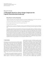
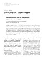
Figure 1: Multistage structure of the chip-level linear BSOR-GSIC
detector.
e
m,g+1
+
−
S
g
e
m,g
S
T
g
R
−1
g,g
μ
y
m,g
y
m−1,g
+
+
y
m,g
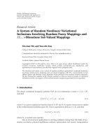
Figure 2: Basic group interference cancellation unit (GICU) for the
chip-level linear BSOR-GSIC detector.
to the decorrelator detector only, the authors in [7] proposed
a chip-level linear GSIC detection scheme that converges not
only to the decorrelator detector as in the case of [6]butto
the LMMSE detector as well.
In this work, we prove that the proposed scheme in [6]is
in fact equivalent to the block Gauss-Seidel iterative method
if the group-detection scheme is the decorrelator detector.
Moreover, we propose a new scheme that is equivalent to the
BSOR iterative method, which is well known to outperform
the conventional block Gauss-Seidel method by an order of
magnitude in terms of convergence speed. We study its con-
vergence behavior and determine the condition of conver-
gence using two different approaches that lead to the same
result.
The work proposed here has two contributions. The first
contribution consists of identifying the structure proposed
in [6] as a block Gauss-Seidel iterative method if the group
detection scheme is the decorrelator detector. This is very
important because it enables the use of the rich theory of
iterative methods to study the convergence behavior of the
scheme in [6]. The second contribution, which is based on
iterative methods theory, consists of proposing a weighted
group SIC structure that is equivalent to the block SOR it-
erative method that is known to exhibit fast convergence.
The work of [7], which is based on matrix transformation,
is therefore totally different from the one proposed here as
the former proposes a group SIC structure that is able to
converge to either the decorrelator detector or the LMMSE
detector. However, the proposed structure converges to the
decorrelator detector only.
Finally, it is important to know that the work reported
here considers linear group detection only. Nonlinear group
detectioncanbefoundinaworksuchastheonereportedin
[8].
2. SYSTEM MODEL AND THE PROPOSED BSOR-BASED
LINEAR GSIC STRUCTURE
In this work, we consider a scenario of an uplink channel
where K users transmit simultaneously over a synchronous
additive white Gaussian noise (AWGN ) channel using binary
phase shift keying (BPSK). Each user is characterized by its
own pseudonoise code of length N chips. The received signal
is expressed in vector form as
r
= SAb + n,(1)
where S is an N
×K matrix of linearly independent spreading
codes, A is a K
× K matrix of the received amplitudes, b is a
K-length vector of transmitted binary symbols, and finally
n is an N-length vector of independently and identically-
distributed additive white Gaussian-distributed samples with
zero-mean and variance σ
2
and are defined as
S
=
s
1
, s
2
, , s
k
, , s
K
∈
−
1
√
N
,
1
√
N
N,K
,
A
= diag
a
1
, a
2
, , a
k
, , a
K
∈ R
K,K
,
b
=
b
1
, b
2
, , b
k
, , b
K
T
∈{−1, 1}
K
.
(2)
Here, s
k
, a
k
,andb
k
are the N × 1 vector of the spreading
code, received amplitude, and data symbol of the kth user,
respectively.
In the following we assume that the K-users are par-
titioned into G groups, where the gth group consists
of U
g
users such that K = U
1
+ U
2
+ ··· + U
G
and
thus the matrix of spreading codes can be partitioned
as S
= (S
1
, S
2
, , S
g
, , S
G
)whereS
g
= (s
g,1
, s
g,2
, ,
s
g,u
g
, , s
g,U
g
) ∈{−1/
√
N,1/
√
N}
N,U
g
.WedefineR = S
T
S
as the cross-correlation matrix of the spreading codes, R
i,j
=
S
T
i
S
j
as the (ith, jth) submatrix of R ,andA
g
as the gth di-
agonal submatrix of matrix A. We assume that R and R
g,g
(for g = 1,2, , G) are nonsingular (since the spreading
codes are assumed to be linearly independent). Therefore,
both matrices R and R
g,g
(for g = 1, 2, , G)arepositive
definite.
The proposed linear weighted GSIC detector which we
call for brevity the chip-level linear BSOR-GSIC detector
consists of group interference cancellation units (GICU) ar-
ranged in a multistage structure of M stagesasillustratedin
Figure 1. The basic linear GICU is shown in Figure 2.The
residual signal e
m,g
at the input of the mth-stage, gth-group
GICU, is first despreaded, multiplied by a transformation
A. Bentrcia et al. 3
matrix R
−1
g,g
and then by a weighting factor μ to estimate the
vector of the partial decision variables y
m,g
of users of the gth
group at the mth stage that is y
m,g
= μR
−1
g,g
S
T
g
e
m,g
.Thevec-
tor of the decision variables of the users of the gth group at
the mth stage is obtained by summing up the vector of de-
cision variables of the previous stage y
m−1,g
and the vector
of partial decision variables of the current stage y
m,g
, that is,
y
m,g
= y
m,g
+ y
m−1,g
.
The residual signal for the next GICU is obtained by
spreading the vector of the partial decision variables y
m,g
and
subtracting it from the residual signal of the current GICU
e
m,g
, that is, e
m,g+1
= e
m,g
− S
g
y
m,g
.
3. CONVERGENCE ANALYSIS
Let e
1,1
= r be the input signal to the chip-level linear BSOR-
GSIC scheme, at the mth stage, the vector of decision vari-
ables of the gth group of users at the mth stage of the chip-
level linear BSOR-GSIC detector is derived as
y
m,g
= μR
−1
g,g
S
T
g
r − μR
−1
g,g
S
T
g
g−1
j=1
S
j
y
m,j
−
G
j=g
S
j
y
m−1,j
+ y
m−1,g
for g = 1, 2, , G.
(3)
Exact derivation of (3)isgiveninAppendix A.Atconver-
gence, we have y
m,g
= y
m−1,g
= y
∞,g
where y
∞,g
is the vector
of decision variables at convergence, therefore (3)isequiva-
lent to
y
∞,g
= μR
−1
g,g
S
T
g
r − μR
−1
g,g
S
T
g
g−1
j=1
S
j
y
∞,j
−
G
j=g
S
j
y
∞,j
+ y
∞,g
for g = 1, 2, , G.
(4)
Equation (4)isequivalentto
μR
−1
g,g
S
T
g
G
j=1
S
j
y
∞,j
= μR
−1
g,g
S
T
g
r for g = 1, 2, , G. (5)
Since R
g,g
is nonsingular, (5) could be written in matrix form
as
S
T
Sy
∞
= S
T
r. (6)
Finally, (6) could be written as
y
∞
= R
−1
S
T
r. (7)
Therefore, if the proposed scheme converges, it converges to
the decorrelator detector.
4. CONDITIONS OF CONVERGENCE
4.1. First approach
This approach allows the identification of the proposed
scheme as the BSOR iterative method, which facilitates the
determination of the condition of convergence. Let us first
establish the analogy between the proposed scheme and the
corresponding iterative method used to solve a set of linear
equations which is known as the BSOR method.
The matrix R could be decomposed into three parts, that
is, R
= D−L−U, where D is block diagonal matrix, that is
D
= diag(R
1,1
, R
2,2
, , R
g,g
, , R
G,G
), and L and U are the
remaining lower-left and upper-right block triangular parts
of R, respectively. After some manipulations, (3)couldbe
written in matrix form as
y
m
=
D − μL
−1
μS
T
r +[
1 − μ)D + μU
y
m−1
(8)
which is exactly the BSOR iteration. See Appendix B for the
exact derivation of (8). Note that if μ
= 1 (this is the case
for the scheme proposed in [6] where the group detection
scheme is the decorrelator detector), the iteration in (8)re-
duces to the block Gauss-Seidel iteration. For the conver-
gence of (8), we use the following corollary [9].
Corollary 1. Let R be an K-by-K hermitian matrix and R =
D
−L −U,whereD is block diagonal matrix, and L and U are
the remaining lower-left and upper-right block tr iangular parts
of R.IfD is positive definite, then the block successive over-
relaxation method is convergent for all y
o
ifandonlyif0<μ<
2andR is positive definite.
Thus, for real μ, the iteration in (8)convergesifμ
∈
]0, 2[. Nevertheless, one should set μ within the interval ]1, 2[
which corresponds to over relaxation (acceleration) since the
interval ]0, 1[ corresponds to under relaxation (deceleration)
and it is basically used to ensure convergence of the block
Gauss-Seidel iteration if it is not convergent. The calculation
of the optimum value of μ for which the convergence is max-
imum depends on the maximum eigenvalue of the iteration
matrix [D
− μL]
−1
[(1 − μ)D + μU], which is complicated to
be computed. However, one can get a cheap fairly-accurate
estimate of the optimum value of μ based on some upper
bound on the maximum eigenvalue of the iteration matrix
as in [10].
4.2. Second approach
This approach was used in [6] to study the convergence be-
havior of the GSIC detector. We adopt it here to determine
the condition of convergence of the proposed scheme. From
Figure 2,wehave
y
m,g
= μR
−1
g,g
S
T
g
e
m,g
+ y
m−1,g
. (9)
For convergence we have
lim
m→∞
∀
g
y
m,g
− y
m−1,g
= lim
m→∞
∀
g
μR
−1
g,g
S
T
g
e
m,g
=
lim
m→∞
∀
g
e
m,g
= 0.
(10)
4 EURASIP Journal on Wireless Communications and Networking
However, we can write e
m,g
as
e
m,g
= e
m,g−1
− μS
g−1
R
−1
g
−1,g−1
S
T
g
−1
e
m,g−1
=
I − μS
g−1
R
−1
g
−1,g−1
S
T
g
−1
e
m,g−1
= B
g−1
e
m,g−1
.
(11)
Following the recursion in (11), (10)canbewrittenas
lim
m→∞
∀
g
e
m,g
= lim
m→∞
∀
g
B
g−1
B
g−2
, , B
1
B
G
, , B
g+1
B
g
e
m−1,g
= lim
m→∞
∀
g
Ω
g
e
m−1,g
= lim
m→∞
∀
g
(Ω
g
)
m−1
e
1,g
= 0.
(12)
Therefore, the chip-level linear BSOR-GSIC converges if
λ
max
Ω
g
< 1, (13)
where λ
max
is the maximum eigenvalue. Since for square ma-
trices X and Y with the same dimensions, the matrices XY
and YX have the same eigenvalues, all the Ω
g
,1 ≤ g ≤ G
have the same eigenvalues. Thus, we consider the case where
g=G.
Consequently, the chip-level linear BSOR-GSIC con-
verges if
λ
max
Ω
G
< 1. (14)
In the following, we consider the following lemma [6].
Lemma 1.
λ
max
Ω
G
≤
G
g=1
λ
max
B
g
. (15)
Thus, if
|λ
max
(B
g
)|,1 ≤ g ≤ G, is less than one, then the
condition in (14) is satisfied and the linear BSOR-GSIC is
guaranteedtoconverge.Wehavemax
1≤g≤G
(|λ
max
(B
g
)|) <1,
thus, max
1≤g≤G
(|λ
max
(I−μS
g
R
−1
g,g
S
T
g
)|) < 1 ⇔ max
1≤g≤G
(|1−
μλ
max
(S
g
R
−1
g,g
S
T
g
)|) < 1; therefore, 0 <μ<2/max
1≤g≤G
(λ
max
(S
g
R
−1
g,g
S
T
g
)), but S
g
R
−1
g,g
S
T
g
is a projection matrix and thus
|λ
max
(S
g
R
−1
g,g
S
T
g
)|=1. Consequently, 0 <μ<2 which is the
same condition as for the BSOR method.
5. COMPUTATIONAL COMPLEXITY
The computational complexity of the proposed detector re-
quires M
G
g
=1
U
g
(4N +1)+
G
g
=1
(11U
3
g
+(3/2)U
2
g
+U
g
), how-
ever, the evaluation of R
g,g
= S
T
g
S
g
needs 2N
G
g=1
U
2
g
flops.
Thus, the total is M
G
g
=1
U
g
(4N+1)+
G
g
=1
(11U
3
g
+(3/2)U
2
g
+
U
g
)+2N
G
g
=1
U
2
g
.
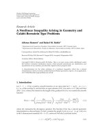
The computational complexity of the symbol-level linear
BSOR-GSIC detector which is illustrated in Figure 3 is
M
G
g=1
⎛
⎜
⎜
⎜
⎝
U
g
G
j=1
j/
=g
2U
j
− 1
+U
g
(G+2)
⎞
⎟
⎟
⎟
⎠
+
G
g=1
11U
3
g
+
3
2
U
2
g
+U
g
.
(16)
y
m−1,G
y
m−1,g+1
y
m−1,g
−R
g,G
.
.
.
−R
g,g+1
1 − μ
y
1,g
μ
R
−1
g,g
−R
g,g−1
−R
g,2
−R
g,1
y
m,g
y
m,g−1
y
m,2
y
m,1
Figure 3: Basic interference cancellation unit for the symbol-level
BSOR-GSIC detector.
However, the evaluation of the matched filter outputs and
R
= S
T
S needs (2N −1)K and 2NK
2
,respectively.Thus,the
total is
(2N
− 1)K + M
G
g=1
U
g
G
j=1j/=g
2U
j
− 1
+ U
g
(G +2)
+
G
g=1
11U
3
g
+
3
2
U
2
g
+ U
g
+2NK
2
(17)
flops. Finally, the decorrelator detector needs at least (lower
bound) [11](11K
3
+(3/2)K
2
+ K)+2NK
2
+(2N −1)K.
It is clear from the expression above that the computa-
tional complexity is a function of the number of usersK and
the number of users within each group U
g
. For the rest of the
parameters such as the processing gain N and the number
of stages M, they are fixed. It is important to note that the
number of stages M needed for convergence should be less
than K so that the computational complexity is in the order
of O (K
2
) rather than O (K
3
) for the decorrelator detector.
This is the situation for the most practical cases as it is shown
in Figure 6. The computational complexity of the proposed
chip-level linear BSOR-GSIC detector and the symbol-level
linear BSOR-GSIC detectors is illustrated in Figure 4.
Finally, note that for the case of the asynchronous
multiapth-fading channel, the received signal is not pro-
cessed in a symbol-by-symbol approach due to the asynchro-
nism of users; instead, a processing window of length W sym-
bols is used. For this case, all the above expressions remain
the same except for the number of users K that should be
substituted by WK.
A. Bentrcia et al. 5
5 101520253035
Number of users (K)
0
5
10
15
×10
4
Number of flops
Proposed chip-level linear BSOR-GSIC detector
Symbol-level linear BSOR-GSIC detector
(a)
5 101520253035
Number of users (K)
0
5
10
15
×10
4
Number of flops
Proposed chip-level linear BSOR-GSIC detector
Symbol-level linear BSOR-GSIC detector
(b)
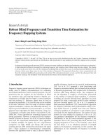
Figure 4: Computational complexity of chip-level and symbol-level BSOR-GSIC detectors for (a) M = K/2,(b)M = K/5.
6. EFFECT OF GROUPING
The effect of users’ grouping on the convergence behavior of
the GSIC detector was studied partially in [6] and in detail in
[12]. It was shown that if the group-detection scheme is the
decorrelator detector, as in our case, the convergence speed
increases with decreasing the number of groups. Thus, it is
favorable to decrease the number of groups as much as pos-
sible. However, decreasing the number of groups results in
increasing the size of each group and therefore increasing the
computational complexity of the proposed detector since the
cross-correlation matrix of each group of users has to be in-
verted. Hence, users’ grouping (the number of groups) is a
system design parameter that is determined by the tradeoff
between convergence speed and computational complexity.
Simulation results showing the effect of grouping are pro-
vided in Section 8.
7. EXTENSION TO THE CASE OF ASYNCHRONOUS
MULTIPATH FADING CDMA CHANNEL
For the case of asynchronous CDMA multipath fading chan-
nel, the structure presented in Figures 1 and 2 are the same,
only the spreading code matrix for the gth group S
g
is sub-
stituted by
S
g
where S
g
= (s
g,1
, s
g,2
, , s
g,u
g
, , s
g,U
g
)and
s
g,u
g
= s
g,u
g
∗h
u
g
.Hereh
u
g
is the vector of the complex fading
coefficients of the u
g
th user’s channel and ∗ denotes the con-
volution operation. Moreover, the conjugate operators (H)
should replace all the transpose operators (T). In this case,
then, the cross-correlation matrix
R = S
H
S is hermitian (as
a result of combining the code cross-correlation matrix and
the complex gain multipath fading channel matrix) and may
become singular in some cases. In [11], it was found that the
cross-correlation matrix is nonsingular if KL
≤ 3N,where
L is the number of multipaths. Based on this practically sup-
ported fact, it follows that the proposed structure will con-
verge to the decorrelator detector if the condition KL
≤ 3N
is satisfied.
Moreover, all the aforementioned convergence analysis
and conditions of convergence are valid for this case as well,
that is, the proposed structure converges to the decorrelator
detector if it converges and the condition of convergence is
0 <μ<2. This will be validated in the simulation section.
8. SIMULATION RESULTS
To show the important reduction in computational com-
plexity one can gain by using the proposed chip-level mul-
tiuser detector, the computational complexity of the chip-
level/symbol-level BSOR-GSIC detectors is evaluated using
the expressions in Section 6 and plotted in Figure 4.HereG
is equal to 4 and N is set to 31 throughout the simulations.
Two cases are assumed: in (a) the number of stages needed to
approximate the decorrelator detector’s average BER perfor-
mance (average BER of all users) is M
= K/2 while in (b) M
= K/5. It is clear that in both cases the computational com-
plexity of the proposed chip-level BSOR-GSIC detector is less
than that of the symbol-level BSOR-GSIC detector and this
difference between the two increases significantly for high
loads, that is, if K/N
≈ 1.
In all subsequent simulations and for sake of compari-
son, one should note that the scheme proposed in [6]which
we use as a benchmark is obtained by setting the relaxation
factor μ
= 1. In the following, we simulate the convergence
behavior of the proposed linear BSOR-GSIC multiuser de-
tector in an AWGN channel. For all simulations conducted,
Gold codes are used and thus the cross-correlation between
users is equal. This removes any effect of certain grouping
or order of cancellation. In Figure 5, the relaxation factor is
varied in the interval ]0, 2[ to illustrate its impact on the aver-
age BER (average of all users’ BER) of the proposed scheme.
The SNR is set to 10 dB, M
= 4, K = 20 and perfect power
controlisassumed.Twodifferent groupings are used, specif-
ically, G
= 2andG = 10 equally sized groups are used. It can
be seen that the minimum achievable average BER level is
for a relaxation factor of about 1.2 for G
= 2and1.4forG =
10. Note that the optimum relaxation factor is different from
one grouping to another; this is mainly because the iteration
matrix [D
− μL]
−1
[(1 − μ)D + μU], which the optimum re-
laxation factor relies on, depends on grouping through the
block diagonal matrix D.
6 EURASIP Journal on Wireless Communications and Networking
0.20.40.60.811.21.41.61.82
Relaxation factor
10
−4
10
−3
10
−2
10
−1
Average BER (dB)
Matched filter detector
Decorrelator detector
Linear BSOR-GSIC detector (G
= 2)
Linear BSOR-GSIC detector (G
= 10)
Figure 5: Average BER of the chip-level linear BSOR-GSIC detector
versus the relaxation factor.
2 4 6 8 10 12 14
Number of chip-level linear BSOR-GSIC stages
10
−3
10
−2
10
−1
10
0
Average BER (dB)
Matched filter detector
Decorrelator detector
Chip-level linear BSOR-GSIC detector (μ
= 1)
Chip-level linear BSOR-GSIC detector (μ
= 1.2)
Chip-level linear BSOR-GSIC detector (μ
= 1.4)
Chip-level linear BSOR-GSIC detector (μ
= 1.6)
Chip-level linear BSOR-GSIC detector (μ
= 1.8)
Figure 6: Convergence behavior of the chip-level linear BSOR-
GSIC detector for different values of the relaxation factor.
In Figure 6, the convergence behavior of the proposed
detector is investigated. The SNR is set to 8 dB, K
= 20,
G
= 2 and perfect power control is assumed. The num-
ber of chip-level linear BSOR-GSIC stages is varied be-
tween 1 and 15 and the average BER performance of the
proposed detector is evaluated for μ
= 1, 1.2, 1.4, 1.6,
and 1.8. It is clear that the chip-level linear BSOR-GSIC
51015202530
Number of users
10
−5
10
−4
10
−3
Average BER (dB)
Matched filter detector
Decorrelator detector
Linear BSOR-GSIC detector (2 stages)
Linear BSOR-GSIC detector (3 stages)
Figure 7: Capacity of the chip-level linear BSOR-GSIC detector for
G
= 2.
12345678910
Near-far ratio
10
−4
10
−3
10
−2
10
−1
10
0
BER (dB)
Matched filter detector
Decorrelator detector
Linear BSOR-GSIC detector (μ
= 1)
Linear BSOR-GSIC detector (μ
= 1.2)
Linear BSOR-GSIC detector (μ
= 1.4)
Linear BSOR-GSIC detector (μ
= 1.6)
Linear BSOR-GSIC detector (μ
= 1.8)
Figure 8: Near-far resistance of the chip-level linear BSOR-GSIC
detector for different values of the relaxation factor (G
= 2).
detector with μ = 1.2 results in the fastest convergence
speed (4 stages are enough to converge to the decorrela-
tor’s detector average BER performance). One can notice
also that for μ
= 1.8 the average BER performance of the
proposed detector exhibits an oscillating behavior which is
expected because we are close to the region of divergence
([2, +
∞)).
A. Bentrcia et al. 7
12345678910
Near-far ratio
10
−4
10
−3
10
−2
10
−1
10
0
BER (dB)
Matched filter detector
Decorrelator detector
Linear BSOR-GSIC detector (μ
= 1)
Linear BSOR-GSIC detector (μ
= 1.2)
Linear BSOR-GSIC detector (μ
= 1.4)
Linear BSOR-GSIC detector (μ
= 1.6)
Linear BSOR-GSIC detector (μ
= 1.8)
Figure 9: Near-far resistance of the chip-level linear BSOR-GSIC
detector for different values of the relaxation factor (G
= 10).
In Figure 7, the capacity (number of users) of the pro-
posed scheme is evaluated. Here, the SNR is set to 10 dB,G
=
2, μ = 1.2 and perfect power control is assumed. We note that
with increasing the number of stages the linear BSOR-GSIC
detector can support more users, for example, for an average
BERof10
−3
theproposed scheme with M = 3cansupportup
to 25 users whereas that with M
= 2cansupport20users.
In Figures 8 and 9, the near-far resistance of the proposed
scheme is assessed. For the near-far ratio, the amplitude of
the first user is fixed and the amplitude of the other users is
varied from one to 20 times that of the first user. The BER
of the first user versus the near-far ratio is then plotted. The
SNR is set to 10 dB, M
= 4, and K = 20. For Figure 8 (G =
2), the near-far resistance is maximum for a relaxation fac-
tor of 1.2 whereas the near-far resistance is maximum for a
relaxation factor of 1.4 in Figure 9 (G
= 10).
In Figure 10, the effect of grouping is illustrated. It is
clear that as the number of groups decreases (the size of
each group increases), the convergence speed of the proposed
structure increases. However, the computational complexity
on the other hand increases as well. This agrees well with the
results obtained in [12].
In Figure 11, we change the relaxation factor in the inter-
val ]0, 2[ to illustrate its impact on the average BER (average
of all users’ BER) of the proposed scheme in an asynchronous
CDMA multipath Rayleigh fading channel. Now, the SNR is
set to 6 dB, M
= 4, K = 24, vehicular A outdoor channel power
delay profile for WCDMA is used and perfect power control
is assumed. Two different groupings are used, specifically, G
= 2andG = 12 equally sized groups are used. We see that
the minimum achievable average BER level is for a relaxation
2 4 6 8 10 12 14 16 18 20
Number of chip-level linear BSOR-GSIC stages
10
−2
Average BER (dB)
Matched filter detector
Decorrelator detector
Linear BSOR-GSIC detector (G
= 2)
Linear BSOR-GSIC detector (G
= 4)
Linear BSOR-GSIC detector (G
= 10)
Figure 10: Effect of grouping on the convergence behavior of the
BSOR-GSIC detector.
0.20.40.60.811.21.41.61.82
Relaxation factor
10
−3
10
−2
10
−1
Average BER (dB)
Matched filter detector
Decorrelator detector
Linear BSOR-GSIC detector (G
= 2)
Linear BSOR-GSIC detector (G
= 12)
Figure 11: Average BER of the chip-level linear BSOR-GSIC detec-
tor versus the relaxation factor for the case of asynchronous CDMA
multipath Rayleigh fading channel.
factor of about 1.2 for G = 2and1.4forG = 10. It is easy
to note that the proposed scheme converges if the relaxation
factor is between 0 and 2. Moreover, the minimum achiev-
able BER is for a relaxation factor of about 0.8, which is in a
good agreement with the theory.
Finally, it is important to note that the detection delay is
reduced by a factor G/K, compared to that of the linear SIC
detector.
8 EURASIP Journal on Wireless Communications and Networking
9. CONCLUSION
In this work, a chip-level linear GSIC structure that is equiv-
alent to the BSOR iterative method and makes use of the
spreading codes directly is proposed; this enables its practi-
cal implementation in long-code CDMA systems (e.g., IS-95
and UMTS) where the cross-correlation matrix is changing
every symbol. Simulation results indicate that significant im-
provement in terms of BER performance, capacity, detection
delay, and near-far resistance can be obtained by using the
proposed scheme compared to that proposed in [6].
APPENDICES
A. DERIVATION OF (3)
The residual signal of the first GICU at the first stage is given
by e
1,1
= r.FromFigure 2, the residual signal of the second
group of users is obtained in terms of the vectors of the deci-
sion variables as
e
1,2
= e
1,1
− S
1
⎛
⎜
⎝
y
1,1
− y
o,1
=0
⎞
⎟
⎠
=
r − S
1
y
1,1
.
(A.1)
Similarly,
e
1,3
= e
1,2
− S
2
⎛
⎜
⎝
y
1,2
− y
o,2
=0
⎞
⎟
⎠
=
r − S
1
y
1,1
− S
2
y
1,2
,
e
1,4
= e
1,3
− S
3
⎛
⎜
⎝
y
1,3
− y
o,3
=0
⎞
⎟
⎠
=
r − S
1
y
1,1
− S
2
y
1,2
− S
3
y
1,3
.
(A.2)
Hence, the residual signal of the gth group of the first stage is
given by
e
1,g
= r −
g−1
j=1
S
j
y
1,j
. (A.3)
The residual signal of the 1st group of the second stage is
given by e
2,1
= e
1,G+1
where e
1,G+1
= r −
G
j=1
S
j
y
1,j
.
The residual signal of the 2nd group of the second stage
is given by
e
2,2
= e
2,1
− S
1
y
2,1
− y
1,1
=
r −
G
j=1
S
j
y
1,j
− S
1
y
2,1
+ S
1
y
1,1
= r −
G
j=2
S
j
y
1,j
− S
1
y
2,1
.
(A.4)
Similarly,
e
2,3
= e
2,2
− S
2
y
2,2
− y
1,2
=
r −
G
j=2
S
j
y
1,j
− S
1
y
2,1
− S
2
y
2,2
+ S
2
y
1,2
= r −
G
j=3
S
j
y
1,j
− S
1
y
2,1
− S
2
y
2,2
= r −
G
j=3
S
j
y
1,j
−
2
j=1
S
j
y
2,j
.
(A.5)
Continuing in the same way, we get the residual signal of the
gth group at the mth stage as
e
m,g
= r −
g−1
j=1
S
j
y
m,j
−
G
j=g
S
j
y
m−1,j
. (A.6)
From Figure 2,wehave
y
m,g
= μR
−1
g,g
S
T
g
e
m,g
+ y
m−1,g
. (A.7)
By substituting (A.6)in(A.7), eventually (3) is obtained.
B. DERIVATION OF (8)
Recall that (3)isgivenby
y
m,g
= μR
−1
g,g
S
T
g
r − μR
−1
g,g
S
T
g
g−1
j=1
S
j
y
m,j
+
G
j=g
S
j
y
m−1,j
+y
m−1,g
for g = 1, 2, , G.
(B.1)
This is equivalent to
y
m,g
= μR
−1
g,g
S
T
g
r − μR
−1
g,g
S
T
g
×
g−1
j=1
S
j
y
m,j
+
G
j=g+1
S
j
y
m−1,j
− S
g
y
m−1,g
+y
m−1,g
= μR
−1
g,g
S
T
g
r − μR
−1
g,g
g
−1
j=1
S
T
g
S
j
y
m,j
− μR
−1
g,g
G
j=g+1
S
T
g
S
j
y
m−1,j
− μR
−1
g,g
S
T
g
S
g
y
m−1,g
+y
m−1,g
= μR
−1
g,g
S
T
g
r − μR
−1
g,g
g−1
j=1
S
T
g
S
j
y
m,j
− μR
−1
g,g
G
j=g+1
S
T
g
S
j
y
m−1,j
− μy
m−1,g
+y
m−1,g
for g = 1, 2, , G.
(B.2)
Multiplying both sides by R
g,g
,weget
R
g,g
y
m,g
= μS
T
g
r − μ
g−1
j=1
S
T
g
S
j
y
m,j
− μ
G
j=g
S
T
g
S
j
y
m−1,j
+(1− μ)R
g,g
y
m−1,g
for g = 1, 2, , G.
(B.3)
A. Bentrcia et al. 9
This can be written in matrix form as
Dy
m
= μS
T
r + μLy
m
+ μUy
m−1
+(1− μ)Dy
m−1
,(B.4)
where D
= diag(R
1,1
, R
2,2
, , R
g,g
, , R
G,G
), L and U are the
remaining lower-left and upper-right block triangular parts
of R, respectively. Hence, (8) is obtained.
ACKNOWLEDGMENT
The authors acknowledge the support provided by King Fahd
University of Petroleum and Minerals.
REFERENCES
[1] J. G. Andrews, “Interference cancellation for cellular systems:
a contemporary overview,” IEEE Wireless Communications,
vol. 12, no. 2, pp. 19–29, 2005.
[2]R.M.Buehrer,N.S.Correal-Mendoza,andB.D.Woerner,
“A simulation comparison of multi-user receivers for cellular
CDMA,” IEEE Transactions on Vehicular Technology, vol. 49,
no. 4, pp. 1065–1085, 2000.
[3] K. Jamal and E. Dahlman, “Multi-stage serial interference can-
cellation for DS-CDMA,” in Proceedings of the IEEE 46th Ve-
hicular Technology Conference (VTC ’96), vol. 2, pp. 671–675,
Atlanta, Ga, USA, April 1996.
[4] L. K. Rasmussen, T. J. Lim, and A. Johansson, “A matrix-
algebraic approach to successive interference cancellation in
CDMA,” IEEE Transactions on Communications, vol. 48, no. 1,
pp. 145–151, 2000.
[5] D. Guo, L. K. Rasmussen, S. Sun, and T. J. Lim, “A matrix-
algebraic approach to linear parallel interference cancellation
in CDMA,” IEEE Transactions on Communications, vol. 48,
no. 1, pp. 152–161, 2000.
[6] A L. Johansson and L. K. Rasmussen, “Linear group-wise
successive interference cancellation in CDMA,” in Proceedings
of the IEEE 5th International Symposium on Spread Spectrum
Techniques & Applications (ISSSTA ’98) , vol. 1, pp. 121–126,
Sun City, South Africa, September 1998.
[7] A. Bentrcia, A. Zerguine, A. U. Sheikh, and M. Benyoucef, “A
new linear group-wise SIC multiuser detector,” IEEE Commu-
nications Letters, vol. 11, no. 2, pp. 176–178, 2007.
[8] A. Kapur and M. K. Varanasi, “Multiuser detection for over-
loaded CDMA systems,” IEEE Transactions on Information
Theory, vol. 49, no. 7, pp. 1728–1742, 2003.
[9] R. S. Varga, Matrix Iterative Analysis, Springer, Berlin, Ger-
maany, 2nd edition, 2000.
[10] A. Grant and C. Schlegel, “Convergence of linear interference
cancellation multiuser receivers,” IEEE Transactions on Com-
munications, vol. 49, no. 10, pp. 1824–1834, 2001.
[11] M. Junti, Multiuser demodulation for DS-CDMA systems in
fading channels, Ph.D. thesis, Department of Electrical Engi-
neering, Oulu University, Oulu, Finland, 1998.
[12] A. Bentrcia, A. Zerguine, and A. U. Sheikh, “The effect of users’
grouping on the convergence behavior of the linear group-
wise SIC,” in Proceedings of the IEEE Region 10 Annual Interna-
tional Conference (TENCON ’04), vol. 2, pp. B501–B504, Chi-
ang Mai, Thailand, November 2004.