Báo cáo hóa học: " Research Article How Equalization Techniques Affect the TCP Performance of MC-CDMA Systems in Correlated Fading Channels" pot
Bạn đang xem bản rút gọn của tài liệu. Xem và tải ngay bản đầy đủ của tài liệu tại đây (1.26 MB, 11 trang )
Hindawi Publishing Corporation
EURASIP Journal on Wireless Communications and Networking
Volume 2008, Article ID 286351, 11 pages
doi:10.1155/2008/286351
Research Article
How Equalization Techniques Affec t the TCP Performance of
MC-CDMA Systems in Correlated Fading Channels
Barbara M. Masini,
1
Giacomo Leonardi,
1
Andrea Conti,
2
Gianni Pasolini,
1
Alessandro Bazzi,
1
Davide Dardari,
1
and Oreste Andrisano
1
1
WiLab, University of Bologna, Viale Risorgimento 2, 40136 Bologna, Italy
2
ENDIF, University of Ferrara, 44100 Ferrara, Italy
Correspondence should be addressed to Barbara M. Masini,
Received 30 April 2007; Revised 24 August 2007; Accepted 2 November 2007
Recommended by Arne Svensson
This paper investigates the impact of several equalization techniques for multicarrier code division multiple access systems on the
performance at both lower and upper layers (i.e., physical and TCP layers). Classical techniques such as maximal ratio combining,
equal gain combining, orthogonality restoring combining, minimum mean square error, as well as a partial equalization (PE) are
investigated in time- and frequency-correlated fading channels with various numbers of interferers. Their impact on the perfor-
mance at upper level is then studied. The results are obtained through an integrated simulation platform carefully reproducing
all main aspects affecting the quality of service perceived by the final user, allowing an investigation of the real gain produced by
signal processing techniques at TCP level.
Copyright © 2008 Barbara M. Masini et al. This is an open access article distributed under the Creative Commons Attribution
License, which permits unrestricted use, distribution, and reproduction in any medium, provided the original work is properly
cited.
1. INTRODUCTION
Multicarrier code division multiple access (MC-CDMA)
techniques have achieved considerable attention and, ow-
ing to their efficiency in counteracting both multiuser in-
terference and frequency selective fading, are also proposed
for fourth generation mobile radio systems (see, e.g., [1–5]).
Several MC-CDMA schemes have been proposed in the lit-
erature (an overview on MC-CDMA systems can be found
in [6]) and different variants can be derived from them. In
this work, we investigate the downlink performance, in real-
istic channel conditions, of the MC-CDMA system presented
in [1, 7]. For what concerns the equalization and combin-
ing techniques, several solutions are here considered with the
aim of evaluating their impact at upper layers through an in-
tegrated approach which takes into account all aspects affect-
ing the performance perceived by the final user, from physical
to application level [8].
In particular, the MC-CDMA scheme here considered
performs the signal spreading in the frequency-domain, thus
resulting in a combination of orthogonal frequency division
multiplexing OFDM and CDMA techniques, and adopts or-
thogonal Walsh-Hadamard (W-H) spreading sequences with
spreading factor equal to the number of subcarriers for the
receiver block schemes). However, in spite of the use of W-H
codes, the orthogonality of the sequences of different users is
lost due to the different fading in each subchannel [4]. There-
fore, in order to improve the system performance, the choice
of the combining technique is a crucial point.
Many combining solutions have been studied in the liter-
ature; in this work, we focus on linear combining techniques
representing low complexity solutions, as requested for mo-
bile terminals implementation. Within the family of linear
combining techniques, equal gain combining (EGC), maxi-
mum ratio combining (MRC), orthogonality restoring com-
bining (ORC) (ORC is also known as zero forcing (ZF)), and
threshold ORC (TORC) have been deeply investigated in the
literature (see, e.g., [6, 7]). It is well known, in fact, that MRC
represents the best choice when the system is noise-limited
because it combines with the higher weights the subchannels
contributions with the higher signal-to-noise ratio (SNR);
on the contrary, when the system is interference-limited,
ORC can be employed to cancel multiuser interference,
with the side effect of enhancing the noise. For this reason,
2 EURASIP Journal on Wireless Communications and Networking
a threshold is introduced with TORC (see, e.g., [9]) to cancel
the contributions of those subchannels highly corrupted by
the noise [10]. Among linear combining techniques, the opti-
mum solution is represented by minimum mean square error
(MMSE) (see, e.g., [11]), but it also requires the knowledge
of the SNR and the number of active users, increasing the re-
ceiver’s complexity. A suboptimal MMSE solution has been,
therefore, proposed which reduces the burden of MMSE im-
plementation [4].
In addition to the above mentioned techniques, in this
paper, we also consider a promising partial equalization (PE)
technique investigated in [12]. In uncorrelated fading chan-
nels its performance is analytically tractable: PE has a mean
bit-error probability (BEP) averaged over fast fading close to
the optimum MMSE, despite having the same complexity of
EGC, MRC, ORC, and TORC.
The novelty of this work consists in evaluating the ef-
fect of the above-mentioned physical level combining tech-
niques not only on the bit-error rate (BER), but also at TCP
level in terms of normalized throughput (whose definition
will be given in Section 6), thus providing an insight on the
performance experienced by the final user. Moreover, real-
istic channel conditions with correlation in both frequency
and time are considered here. In fact, in the literature (see,
e.g., [13–16]), the effects of the equalization techniques are
essentially investigated at the physical level (typically on the
BER), without considering the upper levels performance. If
the upper layers protocols are without memory, the effect
of physical level equalization techniques on the throughput
would directly be related to those on the BER. Since the TCP
protocol is widely affected by the memory effect produced by
the channel correlation, hence, this does not a priori allow
to assert what is the effect of the combining techniques on
the throughput. These considerations suggested us to care-
fully investigate, in this paper, how equalization techniques
play on the TCP throughput.
Moreover, let us emphasize that in order to derive mean-
ingful results, the TCP level performance has been derived
through a complete investigation which carefully takes into
account all main aspects affecting the throughput perceived
by the final user, such as channel characteristics, modulation
and coding schemes, Automatic Repeat reQuest (ARQ) strat-
egy, TCP behavior, and so forth. A simulative approach has
been adopted since it is the only feasible way to take all the
above mentioned aspects into account.
To summarize, the goals of the paper are
(i) to understand how equalization techniques affect the
performance at upper layers in realistic conditions;
(ii) to compare several equalization techniques not only in
terms of physical level performance but also at TCP
level;
(iii) to verify which technique is more suitable to serve dif-
ferent amount of users in realistic channel conditions;
(iv) to maturate the feeling on the presence or absence of
general rules on equalization techniques in different
conditions for a given target TCP performance.
The paper is organized as follows: in Section 2,mod-
elling and assumptions for the investigated MC-CDMA sys-
tem are detailed, and in Section 3 an overview of equaliza-
tion techniques is provided. In Sections 4 and 5, the adopted
simulation platform and its configuration are discussed. In
Section 6, the numerical results are provided and, finally, in
Section 7, the final conclusions are drawn.
2. MODELLING AND ASSUMPTIONS AT PHY LEVEL
Following the MC-CDMA architecture in [6], the number of
subcarriers, M, is equal to the spreading factor. Each data-
symbol is copied over all subcarriers, and multiplied by the
chip assigned to each particular subcarrier. Consequently, the
spreading is performed in the frequency-domain. In the fol-
lowing we will focus our attention on the downlink of an
MC-CDMA system with the commonly accepted assump-
tions such as the system remains always synchronous, and
possible different delays affecting each subcarriers are as-
sumed to be perfectly compensated (see, e.g., [1, 7, 17]).
We consider W-H orthogonal code sequences for the
multiple access and binary phase shift keying (BPSK) modu-
lation. Considering that, exploiting the orthogonality of the
code, all the diff
erent users use the same carriers, the to-
tal transmitted signal results in (being in the downlink, the
phase is the same for all the values of m,thusassumedzero
for simplicity)
s(t)
=
M−1
m=0
+
∞
i=−∞
A
m
[i]g
t −iT
b
cos
2πf
m
t
,
(1)
being
A
m
[i] =
E
b
M
N
u
−1
k=0
c
(k)
m
a
(k)
[i],
(2)
where m is the subcarrier index, i denotes the data index, g(t)
is a rectangular pulse waveform, with duration [0, T]and
unitary energy, T
b
is the bit-time, f
m
= f
0
+ m·Δ f is the
subcarrier frequency (with Δ f
·T and f
0
T integers to have
orthogonal frequencies), E
b
is the energy per bit, M is the
number of subcarriers, N
u
is the number of active users and,
because of the use of orthogonal codes, N
u
≤ M, c
m
is the
mth chip (taking value
±1): and a
(k)
[i] is the data-symbol
transmitted during the ith time-symbol. We assume orthog-
onal sequences
c
(k)
for different users, such that
c
(k)
, c
(k
)
=
M−1
m=0
c
(k)
m
c
(k
)
m
=
Mk= k
,
0 k
=k
.
(3)
In particular, T
b
= T + T
g
is the total OFDM symbol du-
ration, increased with respect to T of a time-guard T
g
in-
serted between consecutive multicarrier symbols to eliminate
the residual intersymbol interference (ISI) due to the channel
delay spread and the inter carrier interference.
As far as the channel model is concerned, we consider two
cases:
(i) uncorrelated Rayleigh fading on each subcarrier;
(ii) time and frequency correlated fading channels.
Barbara M. Masini et al. 3
Table 1: Three rays SUI channels models: delays, attenuations, and
K Ricean factor (K
= 0 means Rayleigh distribution ).
SUI-1 Tap1 Tap2 Tap3
Delay [μs]00.40.9
Attenuation [dB] 0 15 20
K 400
SUI-2 Tap1 Tap2 Tap3
Delay [μs]00.41.1
Attenuation [dB] 0 12 15
K 200
Table 2: Rayleigh three paths (R3P) channels models: delays and
attenuations.
R3P-A Tap1 Tap2 Tap3
Delay [μs]00.41.1
Attenuation [dB] 0 12 15
R3P-B Tap1 Tap2 Tap3
Delay [μs]00.41.1
Attenuation [dB] 0 8 12
R3P-C Tap1 Tap2 Tap3
Delay [μs]00.20.8
Attenuation [dB] 0 12 15
R3P-D Tap1 Tap2 Tap3
Delay [μs]00.20.8
Attenuation [dB] 0 8 12
The assumption of uncorrelated fading among subcar-
riers represents the situation when the subcarriers are suf-
ficiently spaced in frequency (i.e., more than the coherence
bandwidth) or when only a sparse subset of the total amount
of subcarriers is used for a symbol transmission.
In the case of correlated fading channels,
(i) the SUI three-rays channel models [18](adopted,e.g.,
for WiMAX system)
(ii) the Rayleigh three paths (R3P) channel models
have been assumed in the 2 GHz band as summarized in Ta-
bles 1 and 2,respectively.
Since we are now focusing on the downlink, we assume
that considering the nth receiver, the information associated
to different users experiments the same fading. Due to the
CDMA structure of the system, each user receives the infor-
mation of all the users and selects only its own data through
the spreading sequence. The received signal can be written as
r(t)
= s(t)∗h(t)+n(t), (4)
where operator
∗ here denotes the convolution operation,
h(t) is the impulse response of the channel, and n(t) is the
additive white Gaussian noise with two-side power spectral
density (PSD) N
0
/2.
Hence, by denoting with H
m
the channel gain for the mth
subcarrier, the mth signal at the FFT output can be written as
z
m
[i] = H
m
[i]A
m
[i]+n
m
[i].
(5)
r(t)
c
(n)
1
c
(n)
0
c
(n)
M
−1
S/P
Cyclic
prefix
removal
FFT
.
.
.
.
.
.
z
0
z
1
z
M−1
G
0
G
1
G
M−1
M−1
m
=0
v
(n)
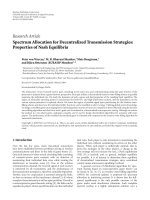
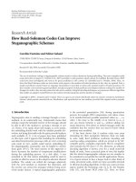
Figure 1: Receiver block-scheme for the nth user.
To b e r i g o r o u s , z
m
[i] = δ
d
·H
m
[i]A
m
[i]+n
m
[i], where δ
d
=
1/(1+T
d
/T) represents the loss of energy caused by the time-
spreading of the impulse. Since δ
d
1, we will neglect it
in the following. Focusing, without loss of generality, on the
nth user, the decision variable (i.e., the test statistic), v
(n)
[i],
is obtained by linearly combining the weighted signals from
each subcarrier as follows (see Figure 1):
v
(n)
[i] =
M−1
m=0
z
m
[i]G
m
c
(n)
m
,
(6)
being G
m
the mth channel weight, which has to be properly
chosen according to the equalization strategy. Its impact on
the performance at both physical and TCP level is investi-
gated.
3. EQUALIZATION TECHNIQUES FOR
MC-CDMA SYSTEMS
Within the family of linear combining techniques, different
schemes based on the channel state information are known
in the literature (see, e.g., [19]), where signals coming from
different subcarriers are weighted by suitable coefficients G
m
.
The EGC technique, for instance, consists in equally
weighting each subchannel contribution and compensating
only the phases, as in
G
m
=
H
∗
m
H
m
,(7)
where operation
∗ stands for complex conjugate.
As investigated in [1], if the number of active users is
negligible with respect to the number of subcarriers, that is,
the system is noise-limited, the best choice is represented by
a combination in which subchannels with the higher SNRs
have the higher weights, as in the MRC, where
G
m
= H
∗
m
. (8)
On the other hand, this choice totally destroys the orthogo-
nality among the codes. For this reason, if the number of ac-
tive users is high (the system is interference-limited), a good
choice is given by restoring at the receiver the orthogonality
among the sequences. This means to cancel the effects of the
channel on the sequences as in ORC, where
G
m
=
1
H
m
. (9)
This implies a total cancellation of the multiuser interference,
but, on the other hand, this method enhances the noise, be-
cause the subchannels with low SNRs have higher weights.
4 EURASIP Journal on Wireless Communications and Networking
App.
Pres.
Sess.
Tr an sp.
Network
DL
Phy.
Destination
Base station
Mobile terminal
Wireless
Wired
···
Server
Tr affic generator, mobility management
TCP, UDP
Client
Fading channel, MC-CDMA,
equalization, ARQ
LLS: Lower layers simulator
ULS: Upper layer simulator
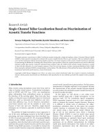
Figure 2: Simulation platform architecture.
In [1] it is shown that in a Rayleigh fading chan-
nel, this technique raises the noise contribution to infinity
(i.e.,
E
|H
m
|
−2
approaches infinity, where E{·} represents
the statistical expectation). Consequently, a correction on G
m
is introduced in [10], as follows:
G
m
= u
H
m
−
ρ
TH
1
H
m
, (10)
where u(
·) is the unitary-step function and the threshold
ρ
TH
is introduced to cancel the contributions of subchannels
highly corrupted by the noise. This method is the so-called
controlled equalization (CE) or TORC technique.
However, exception made for the two opposite cases of
one active user in the presence of noise (giving MRC as the
best solution) and multiple users with negligible noise (giv-
ing ORC), none of the presented methods represents the op-
timum solution for real cases of interest.
Still considering simple equalization techniques, here we
also investigate the PE strategy presented in [12], where co-
efficients G
m
depend on a parameter β as in the following:
G
m
=
H
∗
m
H
m
1+β
. (11)
Note that (7), (8), (9) can be viewed as particular cases of
(11) for which the parameter β assumes the values 0 (EGC),
−1 (MRC) and 1 (ORC), respectively. The key idea is that
since MRC and ORC are optimum in the extreme cases of
noise-limited and interference-limited systems, respectively,
for each intermediate situation there should exist an opti-
mum value of the parameter β which minimizes the mean
BEP averaged over fast fading.
For linear equalization, the optimum solution is the well-
known MMSE technique, whose coefficient expression is
given by
G
m
=
H
∗
m
H
m
2
+1/N
u
γ
, (12)
where N
u
is the number of active users and γ is the mean
SNR averaged over fast fading. However, while the previously
mentioned techniques are only based on the channel state in-
formation, MMSE has the additional complexity to obtain
information about the SNR and the number of active users,
thus representing a more complex solution, especially in the
downlink where the computation is done in the mobile unit.
For this reason a suboptimal MMSE technique was presented
in [4], where the term 1/(
γN
u
)in(12) is replaced by the co-
efficient λ:
λ
=
1
γ
max
·M
, (13)
where
γ
max
is the maximum allowable SNR to achieve a max-
imum acceptable BEP in fully loaded conditions and M is the
number of subcarriers (M is equal to the spreading factor,
thus N
u
= M is the full user capacity).
More complex nonlinear equalizers, such as the maxi-
mum likelihood detection (MLD) and iterative detection, at-
tain better performance [4]. However, in many cases, such
as in mobile radio scenarios, the computation is done in the
mobile unit and it is fundamental to have a detection scheme
capable to attain good performance with low complexity. For
these reasons, in this work, we will focus on linear equaliza-
tion techniques.
Hence, by substituting, for instance, (11)(whichisquite
general including different combining techniques varying the
Barbara M. Masini et al. 5
value of the parameter β)in(6), the decision variable be-
comes
v
(n)
=
U
E
b
δ
d
M
M−1
m=0
H
m
1−β
a
(n)
+
N
M−1
m=0
H
m
−β
n
m
+
I
E
b
δ
d
M
M−1
m=0
N
u
−1
k=0, k=n
H
m
1−β
c
(n)
m
c
(k)
m
a
(k)
,
(14)
where U, N,andI are the useful, noise, and interference
term, respectively. In the same way, the decision variable for
TORC, MMSE, and suboptimum MMSE techniques can be
obtained.
In order to derive the numerical result presented in
Section 6, the value of the decision variable is assessed for
each transmitted symbol during the simulation and the deci-
sion on the correct/erroneous reception of symbols is taken
by comparing it with the threshold 0 (let us recall that we are
considering a BPSK modulation scheme).
4. THE SIMULATION TOOL
In order to investigate the impact of PE on TCP level per-
formance, we realized an accurate MC-CDMA physical level
simulator, carefully reproducing all modulation and equal-
ization aspects, and then we integrated it in our simulation
platform SHINE simulation platform for heterogeneous in-
terworking networks [20] which, as detailed in the following,
allows to reproduce the behavior of the entire protocol pil-
lar of a communication system, from physical to application
level.
SHINE was developed, in particular, with the objective to
reproduce the behavior of wireless access-networks (3G, 4G,
WLAN, WiMAX, etc.), taking care of all aspects related to ev-
ery single protocol level affecting the achieved performance.
In order to have a complete picture of the methodol-
ogy adopted to derive the numerical results provided in
Section 6, further details on SHINE are given in the follow-
ing.
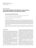
4.1. SHINE architecture.
The SHINE simulation platform has been realized accord-
ing to a client-server structure and is constituted, in particu-
lar, by one server-core simulator hereafter called upper layers
simulator (ULS) and one or more client simulators lower lay-
ers simulators (LLSs), specific for the considered access tech-
nologies (see Figure 2 where, for the sake of clarity, only one
LLS is depicted).
The ULS simulator is, in its turn, constituted by an ac-
cess network(s) side and a core network side: at the access
network(s) side the ULS takes care of all information re-
lated to those users operating within the region covered by
the simulated access-networks, such as their mobility, class
of service, and so forth and of the end-to-end aspects of each
connection, such as the generation of the application-level
traffic and the users’ TCP or UDP dynamics; at the core-
network side, instead, the ULS takes care of all aspects con-
cerning communications.
Focusing the attention on the access network(s) side,
it is worth noting that the ULS structure, being related to
the end-to-end aspects of communications, is independent
on the particular access technology (WLAN, 3G, 4G, etc.)
adopted to establish the user connection.
All aspects related to the access technologies adopted,
hence related to the data-link and physical layers, are man-
aged by LLSs, which are the client simulators and are spe-
cific for each access technology, so that our simulation plat-
form provides the presence of so many LLSs as technologies
adopted in the investigated scenario (see Figure 2).
For the purpose of the investigation described in this pa-
per, we realized an “ad hoc” LLS which reproduces the be-
havior of an MC-CDMA physical level, and, as far as the data
link level is concerned, the medium access control (MAC),
ARQ, and duplexing strategies detailed in the following sec-
tion.
What is really remarkable about SHINE is that ULS and
LLSs are distinct executables; nonetheless the ULS commu-
nicates run time with the LLS through the TCP sockets of the
computer operating-system, thus simulating vertical com-
munications among the protocol layers.
4.2. ULS and LLSs main tasks
As previously stated, the ULS manages the end-to-end as-
pects of each connection (no matter the access technology
supporting it at the physical and data-link levels), hence its
tasks are mainly concerned with communications manage-
ment (connections setup and closure, management of appli-
cation level traffic flows, etc.), the simulation of transport
level protocols (TCP, UDP, etc.) and the processing of sim-
ulation outcomes to provide application level performance.
In particular, the main tasks of ULS are
(i) to set the starting instant of each new traffic session
originated by users according to the arrival statistics of
the traffic class it belongs to (http, e-mail, voice calls,
etc.), as well as users positions within the investigated
scenario;
(ii) to manage connection setup and closure procedures;
(iii) to generate the bit-flows up(down)loaded by users in
each session according to the statistics of their class of
traffic;
(iv) to reproduce the transport protocol behavior;
(v) to perform packet segmentation and reassembly;
(vi) to collect, finally, all simulation outcomes and to gen-
erate the outputs (user satisfaction rate, throughput,
packet delivery delays, etc.) from an end-to-end point
of view.
As for the LLSs, since they are specific for the particular
access technologies investigated, their tasks are mainly con-
cerned with data-link and physical level aspects of commu-
nications and, in particular, are
6 EURASIP Journal on Wireless Communications and Networking
(i) to perform, if required, the call admission control spe-
cific of the technology it simulates and all technology
specific radio resource management actions;
(ii) to manage, if required, the transmission scheduling at
the data-link level level;
(iii) to perform MAC or RLC fragmentation and reassem-
bly of TCP-IP level packets;
(iv) to simulate MAC/RLC behavior of the given technol-
ogy;
(v) to reproduce all physical level procedures related to
each transmission and reception: power control, han-
dover, radio frequency measurements, channel coding,
modulation, information detection, decoding, and so
forth;
(vi) to collect, finally, all simulation outcomes and to gen-
erate the outputs (user satisfaction rate, throughput,
packet delivery delays, etc.) from the wireless links
point of view (i.e., at data-link and physical levels).
The specific configuration of the simulation platform
adopted for the present investigation is detailed in the fol-
lowing section.
5. LLS AND ULS ASSUMPTIONS
ULS assumptions
Since our investigation is focused on the impact of physical
level phenomena (interference, equalization technique, etc.)
on TCP performance, the ULS does not implement any rout-
ing strategy, whose investigation is outside the scope of this
paper. The transport level has been, on the contrary, accu-
rately simulated, since its behavior is very sensitive to the
reliability of communications; all aspects of slow-but-steady
variant of TCP New Reno [21], in particular, have been im-
plemented.
Finally, the simulated application level trafficreproduced
heavy traffic conditions, corresponding to a huge file transfer
(FTP session) saturating the downlink communication ca-
pacity.
Section 6, the quality of service perceived by the final user
is investigated in terms of normalized TCP level throughput.
This performance figure is defined as the average amount
of TCP level data bits that is correctly received in one sec-
ond, normalized to its maximum value (achieved when no
transmission error occurs). Please remind that, before trans-
mission over the wireless channel, TCP data bits are added
of TCP and IP overheads, fragmented, added of RLC-MAC
overheads, coded and finally modulated; all these passages
are carefully reproduced in our simulator.
LLS assumptions
As previously illustrated, LLS should simulate the behavior
at physical and data-link levels of the investigated system.
It follows that we had to simulate not only an MC-CDMA
receiver with different equalization techniques, which are
strictly physical level aspects, but also data link aspects, such
as the MAC and ARQ strategies as well as the duplexing
scheme.
As far as channel coding technique is concerned, we
adopted a 1/2 rate convolutional code with 64 states, polyno-
mial generators (133,171) in octal and hard decision. More-
over, we consider an interleaving process with depth equal to
the codeword length (12 byte in the present work).
As for the MAC strategy, its implementation is intrinsic
in the nature of MC-CDMA signals, which allow multiple
users to transmit in the same frequency and time domains
by simply exploiting the orthogonality of spreading codes.
As far as the ARQ strategy is concerned, the following
mechanism has been implemented in the LLS:
(i) a cumulative ACK is periodically sent to the transmit-
ter when no transmission error is detected;
(ii) a selective negative ACK is sent as soon as a transmis-
sion error is detected.
Finally, with reference to the duplexing technique, we
implemented the time division duplexing (TDD) scheme.
To accommodate asymmetric traffic flows in the two direc-
tions, we assumed a 7/3 downlink/uplink duration ratio and
10 milliseconds of total frame duration.
6. NUMERICAL RESULTS
In this section, the performance at both physical and TCP
levels for the downlink of the above described MC-CDMA
system is investigated. Different conditions in terms of com-
bining technique, propagation channel, number of interfer-
ers, and SNR are considered.
As far as the system parameters are concerned, a to-
tal bandwidth of 14 MHz with M
= 64 equally spaced
subcarriers has been considered, with symbol time T
b
=
4.57 μmicroseconds, and guard time T
g
= T/4, thus greater
than the highest delay of the channel models.
In the two directions, we assume asymmetric trafficflows
with downlink/uplink duration ratio equal to 7/3, a total
frame duration of 10 milliseconds and ideal uplink. Thus,
it is immediate to verify that in this scenario the down-
link maximum available throughput at TCP level results
to be 55.4 Kbps per each user. Since we are interested in
understanding how physical level impacts the TCP through-
put despite its maximum value, which depends on system pa-
rameters, in the following the achieved throughput will be
normalized to the maximum available and presented in per-
centage.
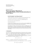
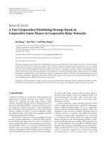
In Figure 3,physicallevelperformanceisreportedinun-
correlated Rayleigh fading channel. The BER at the decoder
input for PE with β
= 0.5 and MRC (i.e., β =−1) as a
function of the SNR (dB) for different numbers of interfer-
ers can be observed. Regarding the PE, the value β
= 0.5has
been considered since it is close to the one providing the op-
timum performance in uncorrelated Rayleigh channel con-
ditions as shown in [12]. Simulation results have been com-
pared with analytical curves obtained following the method-
ology proposed in [12] with very good agreement. This also
confirms the accuracy of our simulator in capturing physi-
cal effects such as multipath propagation, noise, interference,
modulation, and equalization. Figure 3 also allows to ver-
ify that MRC represents the optimal solution in the absence
Barbara M. Masini et al. 7
0 5 10 15
E
b
/N
0
(dB)
10
−4
10
−3
10
−2
10
−1
10
0
BER
MRC, simulation
β
= 0.5, simulation
MRC, analytical
β = 0.5, analytical
MRC, interf.
= 0
β
= 0.5, interf. = 0, 15,
31, 63
MRC, interf.
= 15, 31, 63
Figure 3: BER versus E
b
/N
0
(dB) for partial equalization with β =
−
1(MRC)andβ = 0.5 when varying the number of interferers in
uncorrelated Rayleigh fading channels. Analytical and simulation
results are compared.
of interference. As the number of interferers increases (note
that MC-CDMA systems are usually considered for highly in-
terfered conditions), the performance becomes significantly
worst. On the other hand, PE with β
= 0.5 significantly im-
proves the performance as the interference increases with re-
spect to MRC and makes the system less sensitive to the num-
ber of interferers. In fact, as an example result, in the case
of 15 interferers (i.e., with a system load of 25%), the case
β
= 0.5 outperforms MRC already with 15 interferers.
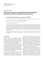
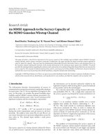
It is now interesting to understand how these behaviors
are confirmed also in time and frequency correlated fading
channels, such as in SUI-1. In Figure 4, the impact of equal-
ization techniques at both physical and TCP levels is inves-
tigated in SUI-1 channel model. Here, the normalized TCP
throughput is reported as a function of E
b
/N
0
in dB as well
as of the number of interferers and of the equalization tech-
niques (β
=−1andβ = 0.5 are considered).
As can be observed, considerations similar to those
made for Figure 3 in uncorrelated channel can be made for
Figure 4(a). Also in this case the impact of the combining
technique and the number of interferers can be clearly ob-
served. Moreover, all considerations suggested by Figure 4(a)
with reference to the physical level are confirmed also at TCP
level (see Figure 4(b)). It is noticeable that the limited sensi-
tivity of the performance to the number of interferers given
by PE with β
= 0.5isevenmoreevidentatTCPlevel.More-
over, the adoption of a particular equalization technique,
such as PE in this case, at physical level can result in rele-
vant throughput gain for several system loads at low SNRs,
whereas the impact at the TCP level of the combining tech-
nique is less evident when the SNR increases. Note that the
performance at TCP level for uncorrelated Rayleigh channel
0 5 10 15
E
b
/N
0
(dB)
10
−4
10
−3
10
−2
10
−1
10
0
BER
MRC
β
= 0.5
Interf.
= 31, 63
Interf.
= 0, 31, 63
Interf.
= 0
(a) BER versus E
b
/N
0
(dB)
0 5 10 15
E
b
/N
0
(dB)
60
80
100
Normalized throughput (%)
MRC, 0 interf.
MRC, 31 interf.
MRC, 63 interf.
β
= 0.5, 0 interf.
β
= 0.5, 31 interf.
β
= 0.5, 63 interf.
(b) Normalized throughput versus E
b
/N
0
(dB)
Figure 4: BER and normalized throughput versus E
b
/N
0
(dB) for
β
=−1(MRC)andβ = 0.5 and for different number of interferers.
Time and frequency correlated SUI-1 channel.
is not investigated due to the TCP characteristic of being par-
ticularly sensitive to correlated events.
This is an example on how our framework enables the
careful verification of the impact of physical level solutions
on the TCP performance.
In Figure 5, the BER and normalized throughput as a
function of E
b
/N
0
(dB) are shown in different types of cor-
related R3P channel models (see Ta bl e 2 for details), in fully
loaded conditions (N
u
= M = 64). The advantage of using
8 EURASIP Journal on Wireless Communications and Networking
0 5 10 15
E
b
/N
0
(dB)
10
−3
10
−2
10
−1
10
0
BER
MRC
β
= 0.5
A
B
C
D
A
B
C
D
(a) BER versus E
b
/N
0
(dB)
0 5 10 15
E
b
/N
0
(dB)
60
80
100
Normalized throughput (%)
β = 0.5
MRC
A
B
C
D
A
B
C
D
(b) Normalized throughput versus E
b
/N
0
(dB)
Figure 5: BER and normalized throughput versus E
b
/N
0
(dB) for
R3P time and frequency correlated channels. Fully loaded system.
avalueofβ = 0.5withrespecttoclassicalMRCcanbeob-
served both in terms of BER in Figure 5(a) and normalized
throughput in Figure 5(b). These results enable a discussion
on the impact of propagation channel on the performance at
TCP level.
A comparison among PE with β
= 0.5 and other lin-
ear combining techniques such as MRC, ORC, and EGC in
SUI-1 channel model is presented in Figure 6 in fully loaded
conditions. As can be observed, PE outperforms the other
techniques both in terms of BER and normalized through-
put. Note also that MRC and ORC techniques do not allow
to achieve the maximum normalized throughput for SNRs of
interest.
In Figure 7, a comparison among optimum MMSE, sub-
optimum MMSE, and PE with β
= 0.5 is given in SUI-1
channel model. In particular, Figure 7(a) shows the BER ver-
0 2 4 6 8 10 12 14
E
b
/N
0
(dB)
10
−3
10
−2
10
−1
BER
MRC
ORC
EGC
β
= 0.5
(a) BER versus E
b
/N
0
(dB)
0 5 10 15
E
b
/N
0
(dB)
60
80
100
Normalized throughput (%)
MRC
ORC
EGC
β
= 0.5
(b) Normalized throughput versus E
b
/N
0
(dB)
Figure 6: BER and normalized throughput versus E
b
/N
0
(dB) for
β
=−1(MRC),β=0.5, β=0(EGC)andβ = 1(ORC)whenthesys-
tem is fully loaded. Time and frequency correlated SUI-1 channel.
sus E
b
/N
0
(dB) for optimum MMSE in the fully loaded con-
dition, suboptimums MMSE and PE with β
= 0.5 for half
and fully loaded system (note that suboptimums MMSE and
PE have the same complexity). For the suboptimal MMSE so-
lution we have assumed
γ
max
= 11.5 (dB) giving BER = 10
−3
in the case of optimal MMSE. As can be observed, MMSE
gives the best performance as expected. For what concern
suboptimal MMSE, its performance is similar to MMSE in
fully loaded case, but it is outperformed by PE technique as
soon as the number of interferers changes.
Barbara M. Masini et al. 9
0 5 10 15
E
b
/N
0
(dB)
10
−4
10
−3
10
−2
10
−1
10
0
BER
Subopt. MMSE, 31 interf.
β
= 0.5, 63 interf.
β
= 0.5, 31 interf.
Subopt. MMSE, 63 interf.
MMSE, 63 interf.
(a) BER versus E
b
/N
0
(dB)
0 5 10 15
E
b
/N
0
(dB)
60
80
100
Normalized throughput (%)
MMSE, 63 interf.
Subopt. MMSE, 63 interf.
β
= 0.5, 31 interf.
β
= 0.5, 63 interf.
Subopt. MMSE, 31 interf.
(b) Normalized throughput versus E
b
/N
0
(dB)
Figure 7: BER and normalized throughput versus E
b
/N
0
(dB) for
time and frequency correlated SUI-1 channel. Comparison among
MMSE, suboptimum MMSE and partial equalization with β
= 0.5.
Note that we are comparing parameterized combining
techniques, such as suboptimums MMSE and PE with fixed
value of the parameter. Since suboptimum MMSE is tuned
for the fully loaded case, a reduction of the actual num-
ber of interferers implies an underestimate of the parameter
1/(N
u
γ)in(12) towards the ORC scheme, thus emphasiz-
ing the effect of thermal noise with respect to the optimum
−1 −0.8 −0.6 −0.4 −0.20 0.20.40.60.81
β
10
−3
10
−2
10
−1
10
0
BER
Uncor., 31 interf.
Uncor., 63 interf.
SUI-1, 31 interf.
SUI-1, 63 interf.
SUI-2, 31 interf.
SUI-2, 63 interf.
R3P-A, 31 interf.
R3P-A, 63 interf.
Uncorrelated
R3P-A
SUI-2
SUI-1
(a) BER versus β
−1 −0.8 −0.6 −0.4 −0.20 0.20.40.60.81
β
60
65
70
75
80
85
90
95
100
Normalized throughput (%)
R3P-A, 31 interf.
R3P-A, 63 interf.
SUI-1, 31 interf.
SUI-1, 63 interf.
SUI-2, 31 interf.
SUI-2, 63 interf.
R3P-A
SUI-2
SUI-1
(b) Normalized throughput versus β
Figure 8: BER and normalized throughput versus β varying the
channel model and the numbers of interferers for E
b
/N
0
= 10 dB.
choice of λ. Same considerations can be derived in terms of
throughput by observing Figure 7(b).
By observing the performance in terms of throughput for
the presented results, we can understand which SNRs are of
interest to study the BER performance. In fact, it is rather
common to find out in the literature asymptotical studies of
the BER behavior (see, e.g., [22] and how to deal with with
10 EURASIP Journal on Wireless Communications and Networking
SNRs of interest in [23]), but, as can be observed, the TCP
throughput is affected by the adopted equalization technique
for low SNRs and it is quite insensible to the physical level
technique when the SNR increases.
Finally, in Figure 8 the impact of the PE parameter, β,
on both the BER and the normalized throughput can be ob-
served for a given SNR varying the channel models and the
system load. In particular, in Figure 8(a) the BER at the de-
coder input is presented as a function of β for E
b
/N
0
= 10 dB
and for different system loads (half loaded and fully loaded
system). A comparison among uncorrelated and correlated
SUI-1, SUI-2, and R3P-A fading channels is also shown. As
can be observed, the choice of β significatively affects the
physical level performance when considering uncorrelated
Rayleigh fading channels, while the BER behavior is more
slightly affected by the values of β in correlated channels con-
ditions. What is remarkable is that the optimum value of
β (minimizing the BER) depends on many parameters: the
channel model, the system loads, and the mean SNR. Note
also the impact of an accurate choice of β on the performance
in terms of throughput perceived by the user in Figure 8(b)
in particular for SUI-2 and R3P-A channel models.
7. CONCLUSIONS
In this paper, we investigated the impact, at both physical and
TCP levels, of different combining techniques for the down-
link of MC-CDMA systems. By means of an integrated plat-
form carefully taking into account all main aspects affecting
the quality of service at the final user, the results in terms
of bit-error rate at the decoder input and the TCP through-
put for a huge file transfer in downlink have been derived.
In our opinion, they enable relevant considerations on how
equalization techniques that improve the performance at the
physical level in the presence of interference, really affects the
quality of service perceived by the final user. In particular,
our numerical results show the impact of the different chan-
nel conditions (such as uncorrelated Rayleigh fading, time
and frequency correlated Rayleigh fading, and SUI channels),
system loads and combining techniques on the performance
at physical and TCP level, allowing us to draw the following
conclusions:
(i) the BER is more sensitive to the combining technique
in uncorrelated channels than in time and frequency
correlated channels;
(ii) the throughput is sensitive to the combining technique
for low and moderate SNRs, while the impact of the
combining technique is less evident when the SNR in-
creases;
(iii) PE technique is less sensitive to the number of interfer-
ers rather than classical MRC or suboptimum MMSE,
providing a good solution for MC-CDMA systems.
This effect is still more evident in terms of throughput.
ACKNOWLEDGMENTS
The authors would like to thank the anonymous Reviewers
for the helpful suggestions enabling us to improve the qual-
ity of the paper. This research work was supported by the
European network of excellence in wireless communications
(NEWCom). This paper reflects part of the activities made in
Project C of the European Network of Excellence in Wireless
Communication (NEWCom).
REFERENCES
[1] N. Yee, J P. Linnartz, and G. Fettweis, “Multi-Carrier-CDMA
in indoor wireless networks,” in Proceedings of the Confer-
ence (PIMRC ’93), pp. 109–113, Yokohama, Japan, September
1993.
[2] K. Fazel, “Performance of CDMA/OFDM for mobile commu-
nication system,” in Proceedings of the 2nd International Con-
ference on Universal Personal Communications (ICUPC ’93),
vol. 2, pp. 975–979, Ottawa, Canada, October 1993.
[3] S. Kaiser, “OFDM-CDMA versus DS-CDMA: performance
evaluation for fading channels,” in Proceedings of the IEEE
International Conference on Communications (ICC ’95),pp.
1722–1726, June 1995.
[4] S. Kaiser, “On the performance of different detection tech-
niques for OFDM-CDMA in fading channels,” in Proceed-
ings of the 1995 IEEE Global Telecommunications Conference
(GLOBECOM ’95), vol. 3, pp. 2059–2063, Singapore, Novem-
ber 1995.
[5] M. Schnell and S. Kaiser, “Diversity considerations for MC-
CDMA systems in mobile communications,” in Proceedings
of the IEEE 4th International Symposium on Spread Spectrum
Techniques and Applications, vol. 1, pp. 131–135, September
1996.
[6] S. Hara and R. Prasad, “Overview of multicarrier CDMA,”
IEEE Communications Magazine, vol. 35, no. 12, pp. 126–133,
1997.
[7] N. Yee and J P. Linnartz, “BER of multi-carrier CDMA in an
indoor Rician fading channel,” in Proceedings of the 27th Asilo-
mar Conference on Signals, Systems & Computers, vol. 1, pp.
426–430, Pacific Grove, Calif, USA, November 1993.
[8] O. Andrisano, D. Dardari, and G. Mazzini, “An integrated ap-
proach for the design of wide-band wireless LANs,” in Proceed-
ings of the IEEE (ICT ’98), pp. 121–126, Porto Carras, Greece,
June 1998.
[9]J.G.Proakis,Digital Communications, McGraw-Hill, New
York, NY, USA, 4th edition, 2001.
[10] N. Yee and J P. Linnartz, “Controlled equalization of multi-
carrier CDMA in an indoor Rician fading channel,” in Pro-
ceedings of the 1994 IEEE 44th Vehicular Technology Conference,
vol. 3, pp. 1665–1669, Stockholm, Sweden, June 1994.
[11] N. Yee and J P. Linnartz, “Wiener filtering for Multi-Carrier
CDMA,” in Proceedings of the IEEE Conference on Personal
Indoor Mobile Radio Communications (PIMRC) and Wireless
Computer Networks (WCN), vol. 4, pp. 1344–1347, Hague,
The Netherlands, September 1994.
[12] A. Conti, B. Masini, F. Zabini, and O. Andrisano, “On the
down-link performance of multi-carrier CDMA systems with
partial equalization,” IEEE Transactions on Wireless Communi-
cations, vol. 6, no. 1, pp. 230–239, 2007.
[13] S. Kaiser, “OFDM code-division multiplexing in fading chan-
nels,” IEEE Transactions on Communications,vol.50,no.8,pp.
1266–1273, 2002.
[14] I. Cosovic and S. Kaiser, “Exploitation of diversity in MC-
CDMA systems,” in Proceedings of the 6th IEE International
Conference on 3G and Beyond (3G ’05), pp. 1–5, Washington,
DC, USA, November 2005.
Barbara M. Masini et al. 11
[15] I. Cosovic, M. Schnell, and A. Springer, “Combined equaliza-
tion for uplink MC-CDMA in Rayleigh fading channels,” IEEE
Transactions on Communications, vol. 53, no. 10, pp. 1609–
1614, 2005.
[16] I. Cosovic, M. Schnell, and A. Springer, “Pre-, post-, and
combined-equalization single-user bounds for MC-CDMA,”
in Proceedings of the 7th European Conference on Wireless Tech-
nology (ECWT ’04), pp. 321–324, Amsterdam, The Nether-
lands, October 2004.
[17] S. B. Slimane, “Partial equalization of Multi-Carrier CDMA in
frequency selective fading channels,” in Proceedings of the IEEE
International Conference on Communications, vol. 1, pp. 26–30,
New Orleans, La, USA, June 2000.
[18] V. Erceg, K. V. S. Hari, M. S. Smith, et al., “Channel
Models for Fixed Wireless Applications,” revised version of
the document IEEE 802.16.3c-01/29r4. The IEEE 802.16
Working Group on Broadband Wireless Access Standards,
/>01.pdf.
[19] M. K. Simon and M S. Alouini, Digital Communication over
Fading Channels: A Unified Approach to Performance Analysis,
John Wiley & Sons, New York, NY, USA, 1st edition, 2000.
[20] A. Bazzi, C. Gambetti, and G. Pasolini, “SHINE: simulation
platform for heterogeneous interworking networks,” in Pro-
ceedings of the IEEE International Conference on Communica-
tions ( ICC ’06), Istanbul, Turkey, June 2006.
[21] S. Floyd and T. Henderson, “The NewReno Modification to
TCP’s Fast Recovery Algorithm,” RFC 2582, April 1999.
[22] H. S. Abdel-Ghaffar and S. Pasupathy, “Asymptotical
performance of M-ary and binary signals over multi-
path/multichannel Rayleigh and Rician fading,” IEEE Trans-
actions on Communications, vol. 43, no. 11, pp. 2721–2731,
1995.
[23] A. Conti, M. Z. Win, and M. Chiani, “On the inverse symbol-
error probability for diversity reception,” IEEE Transactions on
Communications, vol. 51, no. 5, pp. 753–756, 2003.