Báo cáo hóa học: " Narrow ridge waveguide high power single mode 1.3-lm InAs/InGaAs ten-layer quantum dot lasers" pptx
Bạn đang xem bản rút gọn của tài liệu. Xem và tải ngay bản đầy đủ của tài liệu tại đây (296.01 KB, 5 trang )
NANO EXPRESS
Narrow ridge waveguide high power single mode 1.3-lm
InAs/InGaAs ten-layer quantum dot lasers
Q. Cao Æ S. F. Yoon Æ C. Y. Liu Æ C. Y. Ngo
Received: 18 April 2007 / Accepted: 23 May 2007 / Published online: 14 June 2007
Ó to the authors 2007
Abstract Ten-layer InAs/In
0.15
Ga
0.85
As quantum dot
(QD) laser structures have been grown using molecular
beam epitaxy (MBE) on GaAs (001) substrate. Using the
pulsed anodic oxidation technique, narrow (2 lm) ridge
waveguide (RWG) InAs QD lasers have been fabricated.
Under continuous wave operation, the InAs QD laser
(2 · 2,000 lm
2
) delivered total output power of up to
272.6 mW at 10 °C at 1.3 lm. Under pulsed operation,
where the device heating is greatly minimized, the InAs
QD laser (2 · 2,000 lm
2
) delivered extremely high output
power (both facets) of up to 1.22 W at 20 °C, at high
external differential quantum efficiency of 96%. Far field
pattern measurement of the 2-lm RWG InAs QD lasers
showed single lateral mode operation.
Keywords Molecular beam epitaxy ÁSingle lateral mode Á
InAs/InGaAs quantum dot Á Pulsed anodic oxidation Á
Laser diode
Introduction
High-performance GaAs-based quantum dot (QD) lasers
are of great interest due to their potential applications in
advanced optical fiber communication systems [1–9]. The
reduced density of states arising from the three-dimen-
sional confinement of carriers give QDs the advantages to
be able to achieve low threshold current density and high
differential gain [2, 5, 6, 10]. High power, high efficiency,
and temperature insensitivity have been reported for InAs
QD lasers [3, 5, 6]. However, the laser performance is
commonly restrained by the intrinsically low surface den-
sity (N
QD
) of a single-layer QD structure [7]. As the
achievable optical gain, which is limited by saturated gain
(G
sat
), in a single-layer QD is proportional to the surface
density, i.e., G
sat
µ N
QD
, the finite N
QD
of the order of
10
10
cm
–2
in a self-assembled single-layer QD structure
directly limits the available optical gain in the ground state
(GS) [7, 8]. This leads to undesirable excited state (ES)
lasing at high current and/or high temperature [9].
Over the last decade, it has been shown that utilization
of multiple QD layers is an effective way to prevent gain
saturation [3, 5–7, 9, 11–15]. Ideally, the saturation gain [6]
and maximum output power increase [11] following in-
crease in the number of QD layers. However in practice,
the high strain accumulated in the multiple-layer QD active
region generates defects formation, leading to degradation
in the threshold current (I
th
) and internal quantum effi-
ciency (g
i
)[6, 14]. This limits the number of stacking
layers that can be incorporated into the QD active region.
So far, laser structures comprising three to five QD active
layers have been reported [5, 9, 11–13, 16, 17]. However,
there have been relatively few reports [3, 6, 14, 15]onQD
lasers emitting at 1.3 lm or above, with the number of QD
active layers exceeding five.
Furthermore, single mode laser operation [12, 13,
18–20] is desirable for better device to fiber coupling
efficiency in optical fiber communication systems. This
could be achieved using narrow ridge waveguide (RWG)
laser structure [12, 13, 15, 18–21]. There have been many
studies of RWG structure in InGaAsN/GaAs QW and
In(Ga)As/GaAs QD systems, where light emission at
1.3 lm is realized. High power single mode operation has
been achieved in InGaAsN/GaAs QW lasers, where high
Q. Cao Á S. F. Yoon (&) Á C. Y. Liu Á C. Y. Ngo
School of Electrical and Electronic Engineering, Nanyang
Technological University, Nanyang Avenue, Singapore 639798,
Republic of Singapore
e-mail:
123
Nanoscale Res Lett (2007) 2:303–307
DOI 10.1007/s11671-007-9066-4
performance in terms of light output, beam quality and
high-temperature operation have been demonstrated [18–
20]. Comparatively, fewer works have been reported on
single mode operation in high performance In(Ga)As/GaAs
QD lasers [12, 13]. It is commonly known that as the ridge
width narrows, the sidewall condition plays an important
role in the laser performance, where sidewall scattering/
recombination [22] tends to degrade the laser performance.
Undesirable lateral current spreading resulting from side-
wall effects have been investigated for improving the laser
structure design [22–24]. Moreover, the small lasing vol-
ume in narrow RWG lasers may increase the optical losses
as result of process related scattering. Such effects may
increase the threshold current density and limit high tem-
perature operation [25]. A key factor to achieve single
mode emission is narrow ridge width of the QD laser
structure. To obtain strong index guiding and to suppress
current spreading, careful balance between etch depth and
ridge width should be accomplished [22]. Our previous
works [26, 27] have shown that by optimizing the pulsed
anodic oxidation (PAO) process after sidewall etching,
high-performance RWG lasers with reduced lateral current
spreading could be achieved.
While we have previously demonstrated [14] low
transparency current density and high temperature charac-
teristic ten-layer InAs broad area QD lasers, this paper
reports the characteristics of ten-layer narrow ridge width
(2 lm) InAs QD lasers. We will show results from devices
with high output power of 272.6 mW (both facets) oper-
ated in continuous wave (CW) mode under GS lasing at
1.3 lm emission. Devices of dimension 2 · 2,000 lm
2
operated under pulsed mode (pulse width = 1 ls, duty
cycle = 1%) showed extremely high output power of up to
610 mW per facet. The narrow RWG InAs QD lasers also
emit in single lateral mode.
Experimental details
The ten-layer self-assembled InAs/InGaAs QD laser
structures were grown using molecular beam epitaxy
(MBE) on GaAs (100) substrates. Separate confinement
layers based on 1.5-lm-thick Al
0.35
Ga
0.65
As cladding lay-
ers doped with C and Si for p- and n-type conductivity,
respectively (refer to Fig. 1a), were used. The QD active
region (refer to Fig. 1b), consists of 10 layers of InAs
(2.32 ML)/In
0.15
Ga
0.85
As (5 nm) QDs separated by a
33 nm-thick GaAs spacer inserted into two Al
0.35
Ga
0.65
As
cladding layers. p-doping modulation (C: 5 · 10
17
cm
-3
)
was incorporated into the 10 nm GaAs layer in the middle
of each 33 nm-thick spacer between the QD rows. A
200 nm-thick P
+
-GaAs cap layer was used for electrical
contact. Evidence of high optical quality of the QD laser
structure was obtained from photoluminescence (PL)
measurements. Details from the PL study were published
elsewhere [14]. GS photoluminescence up to 100 °C was
demonstrated from this QD laser structure. Though both
GS and first excited state (ES) transitions were observed,
GS emissions remained dominant even at high excitation
power and high temperature. This indicates that the QD
laser structure exhibits strong luminescent efficiency
without degradation in material quality even with ten QD
layers [14]. Normally, QD lasers switch to the ES lasing at
high temperature due to reduction of the GS gain as result
of thermally activated carrier loss and increased band-fill-
ing in the ES as the GS gain becomes saturated [28]. Since
GS emission was maintained in the InAs QD laser structure
up to 100°C under high excitation level, this indicates the
availability of high GS gain from the p-doped ten-layer
InAs QD active region.
The wafer was processed into 2 lm wide RWG lasers
by standard wet chemical etching using a solution of
Metal (Au/Ti)
P-doped Al
035
Ga
065
As (1000nm) P=1×
×
10
18
P-doped Al
035
Ga
065
As (500nm) P=5×10
17
N-doped Al
035
Ga
065
As (500nm) N=5×10
17
N-doped Al
035
Ga
065
As (1000nm) N=1×10
18
N-doped GaAs Buffer (500nm) N=3×10
18
P-doped GaAs (200nm) P=1×10
20
P-doped Al
035
Ga
065
As (20nm) P=3×10
18
GaAs (9nm)
P-doped GaAs (10nm) P=5×10
17
GaAs (14nm)
In
0.15
Ga
0.85
As (5nm)
InAs (0.8nm)
GaAs Barrier (33nm)
N-doped Al
035
Ga
065
As (20nm) N=3×10
18
N-doped GaAs substrate
Metal (Ni/Ge/Au/Ni/Au)
×10
(a)
(b)
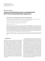
Fig. 1 (a) Schematic
illustration of the InAs/InGaAs
ten-layer QD laser structure. (b)
TEM image of the InAs QD
active region. The scale bar is
100 nm
304 Nanoscale Res Lett (2007) 2:303–307
123
H
3
PO
4
:H
2
O
2
:H
2
O (1:1:5). Good control of the etch depth is
necessary to achieve single lateral mode operation, since
the refractive index step between the ridge and trench re-
gion is determined by the etch depth. Through optimization
of the ridge height [27, 29], the entire p-doped layers above
the QD active region outside the ridge was etched before
the pulsed anodic oxidation (PAO) process. A 200 nm-
thick oxide layer was formed by PAO, whose experimental
setup is described in Ref. [30]. Subsequently, p-type ohmic
contact layers (Ti/Au, 50/300 nm) were deposited by
electron beam evaporation, while n-type ohmic contact
layers (Ni/Ge/Au/Ni/Au, 5/20/100/25/300 nm) were
deposited on the backside of the substrate following lap-
ping down to ~100 lm. All samples were annealed at
410 °C for 3 min in N
2
ambient. Finally, the wafers were
cleaved into laser bars of different cavity lengths (550–
3,000 lm), whereas, the ridge width was kept constant for
all the laser devices at w = 2 lm. The output power (P)
versus injection current (I)(P–I) characteristics were
measured under CW operation at 10 °C. To minimize de-
vice heating, the InAs QD lasers were also tested under
pulsed operation (pulse width = 1 ls, duty cycle = 1%) at
20 °C. The far field patterns (parallel to the junction plane)
of the InAs QD lasers were measured under the above
mentioned pulsed conditions at 20 °C.
Results and discussion
Figure 2a shows a cross-sectional scanning electron
microscopy (SEM) image of the narrow RWG laser
structure investigated in this work. A stripe width of 2 lm
is clearly shown and the etching was stopped right above
the upper cladding layer as described previously. The
oxidized AlGaAs layer (~200 nm thick) formed by PAO
above the active region is observed in Fig. 2a. The oxide
layer is smooth and uniform, and no signs of under-cut
were observed. Meanwhile, the ten-stacked QD layers are
clearly presented in Fig. 2b with better contrast.
Figure 3 shows the plot of CW output power and biasing
voltage (V) as function of injection current, I taken from
devices of dimension 2 · 2,000 lm
2
at 10 °C. High output
power (both facets) of around 272.6 mW was obtained.
The output power eventually saturated at 800 mA due to
thermal rollover. However, distinct kinks were observed
under high current injection, which we attribute to mode
hopping caused by device heating [31], rather than current-
induced ground-to-excited-state lasing transition [16]. The
latter mechanism, caused by finite intraband relaxation
time combined with limited density of GS in QD structures,
is only significant for short-cavity devices, in which the
number of available ground states for carrier relaxation is
reduced [14, 17]. Furthermore, a report by Markus et al.
[17] indicated that the ES threshold current is more than
10 times higher than GS threshold current for cavity length
of 2,000 lm, which is not true in our case. The lasing
spectrum from an InAs QD laser (50 · 5,000 lm
2
)is
presented in the inset of Fig. 3 for verification. The lasing
wavelengths of 1,308 nm and 1,351.1 nm are obtained
under the injection current of 354 mA at 25 °C and 1 A at
100 °C, respectively. It does prove GS lasing from such
laser structure under high injection current level even at
high temperature up to 100 ° C. Based on above analysis, it
is reasonable to conclude that the kink in power output is
most likely caused by longitudinal mode hopping, which
arises primarily due to temperature fluctuation in the laser.
The heating of the laser active region by the injection
current under CW operation, may cause nonlinearity in
Fig. 2 (a) Cross-sectional SEM
image of the InAs QD laser
fabricated using PAO. (b) SEM
image of the ten-stacked InAs
QD layers for the same device
as in (a)
Fig. 3 P–I–V characteristics of a 2 · 2,000 lm
2
RWG InAs QD
laser in CW operation. The output power is obtained from the front
as-cleaved facet. Inset shows the lasing spectrum from an InAs QD
laser (50 · 5,000 lm
2
). The laser showed ground state lasing from
25 °C up to 100 °C with the injection current up to 1 A
Nanoscale Res Lett (2007) 2:303–307 305
123
gain, which consequently changes the oscillation wave-
length as well as output power.
The unstable switching between modes causes intensity
noise, resulting in degradation in the laser performance
[31]. Furthermore, mode hopping is expected to be more
pronounced in narrow ridge structures where the cross-
sectional area is relatively small. More detailed investiga-
tion on the mode hopping behavior is warranted to further
study this effect. Nevertheless, our observations from
operating the device in CW mode suggest the presence of a
significant heating effect.
To alleviate the effects of device heating in CW oper-
ation, the InAs QD lasers were measured under pulsed
operation (1 ls, duty cycle = 1%) at 20 °C. Figure 4
shows the output power–current characteristics for a
2 · 2,000 lm
2
device with uncoated facets. Extremely
high output power of 610 mW (per facet) was recorded at
injection current of 1.6 A. To the best of our knowledge,
this is among the highest value of output power in the
literature ever reported for narrow RWG InAs QD lasers.
Compared with CW operation, power saturation and kinks
in the output power characteristics are greatly reduced in
pulsed mode, which is attributed to reduction in device
heating. High slope efficiency g of 0.46 W A
–1
per facet
was obtained from the P–I curve, and near ideal external
differential quantum efficiency g
d
of 96% was calculated
from Eq. 1 [32]:
g
d
¼ 2 Â
DP=DðhmÞ
DI=Dq
¼ 2 Â
DP
DI
Â
k ðlmÞ
1:24 ðeVÞ
ð1Þ
where g
d
is the external differential quantum efficiency of
the InAs QD laser, and DP/DI is the slope efficiency ob-
tained from the measured P–I characteristics. h is the
Planck’s constant, q the electronic charge, frequency
m ¼
c
k
, where c is the speed of light in vacuum, and k the
emission wavelength of the InAs QD laser. The far-field
patterns (FFP) shown in the inset of Fig. 4 indicate the
InAs RWG QD laser emitted at single lateral mode under
different injection current levels from 450 mA to 600 mA.
The laser beam divergence in the lateral direction is around
4° at the injection current levels investigated, indicating
excellent beam quality in these devices.
Ouyang et al. [15] has reported narrow RWG InAs QD
lasers with ridge width of 8 lm, and observed that lasers
with deep-mesa geometry exhibited superior characteristics
compared with shallow-mesa devices. Under pulsed oper-
ation (500 ns, 5 kHz), the HR/uncoated InAs QD laser of
dimension 8 · 1,500 lm
2
showed high external differen-
tial efficiency of 50% and low threshold current density of
~130 A/cm
2
at moderate output power ~6 mW. Compared
with this report, our results show that the ten-layer InAs
QD lasers fabricated using PAO were able to deliver
comparable, and in some cases better performance with
near ideal external differential efficiency of 96% and ex-
tremely high output power of 610 mW/facet under pulsed
operation. Furthermore, the devices also exhibit single
lateral mode emission.
The output power P and external differential quantum
efficiency g
d
of our ten-layer InAs narrow RWG QD lasers
are among the highest values in the 1.29–1.30 lm wave-
length range ever reported. The high device performance is
attributed to the high quality QD laser structure and opti-
mized self-aligned PAO method compared with conven-
tional SiO
2
confinement. The better passivation of the
sidewalls by the native oxide formed by the PAO process
could contribute to the reduction in nonradiative centers
between the sidewall and oxide layer. This is particularly
critical in narrow RWG devices such as the ones investi-
gated in this study. These factors are believed to have
contributed significantly to the high performance observed
in our narrow RWG devices.
Conclusions
In summary, narrow RWG lasers based on ten-layer
InAs/InGaAs QD active region have been fabricated and
characterized. Devices fabricated using an optimized
PAO process exhibited GS lasing at high total output
power of 272.6 mW at ~1.3 lm under CW operation.
Extremely high single lateral mode output power of
610 mW/facet was achieved in pulsed operation with
minimal power saturation under high current injection.
High slope efficiency of 0.46 W A
–1
per facet, near ideal
external differential quantum efficiency of 96% and low
lateral beam divergence of 4° have been achieved in the
devices.
0
0
100
1750150012501000750500
250
200
300
400
500
600
700
-15 -10 -5 0 5 10 15
ytisnetnI
Lateral Angle (degree)
450 mA
500 mA
600 mA
)Wm( rewop tuptuO
Current (mA)
InAs QD LD
2000 x 2
µm
2
Pulsed mode (1µs, 1%)
Fig. 4 P–I characteristics of a 2 · 2,000 lm
2
RWG InAs QD laser in
pulsed operation (1ls, duty cycle = 1%) at 20 °C. Inset shows the
lateral far-field pattern at different injection current levels in pulsed
mode (1 ls, duty cycle = 1%) at 20 °C
306 Nanoscale Res Lett (2007) 2:303–307
123
Acknowledgements This research is partially sponsored by
A*STAR under the ONFIG-II program SERC Grant No. 042 108
0098. The authors would also like to acknowledge the assistance of
Dr Tong Cunzhu for his useful inputs to this research.
References
1. S.F. Yoon, C.Y. Liu, Z.Z. Sun, K.C. Yew, Nanoscale Res. Lett. 1,
20 (2006)
2. S. Mokkapati, M. Buda, H.H. Tan, C. Jagadish, Appl. Phys. Lett.
88, 161121 (2006)
3. S.S. Mikhrin, A.R. Kovsh, I.L. Krestnikov, A.V. Kozhukohov,
D.A. Livshits, N.N. Ledentsov, Yu.M. Shernyakov, I.I. Novikov,
M.V. Maximov, V.M. Ustinov, Zh.I. Alferov, Semicond. Sci.
Technol. 20, 340 (2005)
4. Y.H. Chen, X.L. Ye, Z.G. Wang, Nanoscale Res. Lett. 1,79
(2006)
5. O.B. Shchekin, D.G. Deppe, IEEE Photon. Technol. Lett. 14,
1231 (2002)
6. A.R. Kovsh, N.A. Maleev, A.E. Zhukov, S.S. Mikhrin, A.P.
Vasil’ev, Yu.M. Shernyakov, M.V. Maximov. D.A. Livshits.
V.M. Ustinov, Zh.I. Alferov, N.N. Ledentsov, D. Bimberg,
Electron. Lett. 38, 1104 (2002)
7. O.G. Schmidt, N. Kirstaedter, N.N. Ledentsov, M.H. Mao, D.
Bimberg, V.M. Ustinov, A.Y. Egorov, A.E. Zhukov, M.V.
Maximov, P.S. Kop’ev, Z.I. Alferov Electron. Lett. 32, 1302
(1996)
8. C.Y. Liu, S.F. Yoon, Q. Cao, C.Z. Tong, Z.Z. Sun, Nanotech-
nology 17, 5627 (2006)
9. H.Y. Liu, D.T. Childs, T.J. Badcock, K.M. Groom, I.R. Sellers,
M. Hopkinson, R.A. Hogg, D.J. Robbins, D.J. Mowbray, M.S.
Skolnick, IEEE Photonics Technol. Lett. 17, 1139 (2005)
10. M. Benyoucef, A. Rastelli, O.G. Schmidt, S.M. Ulrich, P.
Michler, Nanoscale Res. Lett. 1, 172 (2006)
11. L.V. Asryan, Appl. Phys. Lett. 88, 073107 (2006)
12. M.V. Maximov, Yu.M. Shernyakov, I.N. Kaiander, D.A. Beda-
rev, E.Yu. Kondrat’eva, P.S. kop’ev, A.R. Kovsh, N.A. Maleev,
S.S. Mikhrin, A.F. Tsatsul’nikov, V.M. Ustinov, B.V. Volovik,
A.E. Zhukov, Zh.J. Alferov, N.N. Ledentsov, D. Bimberg,
Electron. Lett. 35, 2038 (1999)
13. S.S. Mikhrin, A.E. Zhukov A.R. Kovsh, N.A. Maleev, V.M.
Ustinov, Yu.M. Shernyakov, I.N. Kayander, E.Yu. Kondrat’eva,
D.A. Livshits, I.S. Tarasov, M.V. Maksimov, A.F. Tsatsul’nikov,
N.N. Ledentsov, P.S. Kop’ev D. Bimberg, Zh.I. Alferov, Semi-
conductors 34, 119 (2000)
14. C.Y. Liu, S.F. Yoon, Q. Cao, C.Z. Tong, H.F. Li, Appl. Phys.
Lett. 90, 041103 (2007)
15. D. Ouyang, N.N. Ledentsov, D. Bimberg, A.R. Kovsh. A.E.
Zhukov, S.S. Mikhrin, V.M. Ustinov, Semicond. Sci. Technol.
18, L53 (2003)
16. A.E. Zhukov, A.R. Kovsh, D.A. Livshits, V.M. Ustinov, Zh.I.
Alferov, Semicond. Sci. Technol. 18, 774 (2003)
17. A. Markus, J.X. Chen, C. Paranthoen, A. Fiore, C. Platz, O.
Gauthier-Lafaye, Appl. Phys. Lett. 82, 1818 (2003)
18. A.R. Kovsh, J.S. Wang, R.S. Hsiao, L.P. Chen, D.A. Livshits, G.
Lin, V.M. Ustinov, J.Y. Chi, Electron. Lett. 39, 1726 (2003)
19. C.S. Peng, N. Laine, J. Konttinen, S. Karirnne, T. Jouhti, M.
Pessa, Electron. Lett. 40, 604 (2004)
20. N. Tansu, J.Y. Yeh, L.J. Mawst, J. Phys.: Condens. Matter. 16,
S3277 (2004)
21. A. Caliman, A. Ramdane, D. Meichenin, L. Manin. B. Sermage,
G. Ungaro, L. Travers, J.C. Harmand, Electron. Lett. 38, 710
(2002)
22. M. Legge, G. Bacher, S. Bader, A. Forchel, H J. Lugauer, A.
Waag, G. Landwehr, IEEE Photon. Technol. Lett. 12, 236 (2000)
23. S.Y. Hu, D.B. Young, A.C. Gossard, L.A. Coldren, IEEE J.
Quantum Electron. 30, 2245 (1994)
24. D. Ban, E.H. Sargent, K. Hinzer, St. Dixon-Warren, A.J.
SpringThorpe, J.K. White, Appl. Phys. Lett. 82
, 4166 (2003)
25. S. Slivken, J.S. Yu, A. Evans, J. David, L. Doris, M. Razeghi,
IEEE Photon. Technol. 16, 1041 (2004)
26. C.Y. Liu, Y. Qu, S. Yuan, S.F. Yoon, Appl. Phys. Lett. 85, 4594
(2004)
27. C.Y. Liu, S.F. Yoon, S.Z. Wang, S. Yuan, J.R. Dong, J.H. Teng,
S.J. Chua, IEE Proc. Optoelectron. 152, 205 (2005)
28. X.D. Huang, A. Stintz, C.P. Hains, G.T. Liu, J.L. Cheng, K.J.
Malloy, IEEE Photon. Technol. Lett. 12, 227 (2000)
29. C.Y. Liu, S.F. Yoon, W.J. Fan. A. Uddin, S. Yuan, IEEE Photon.
Technol. Lett. 18, 791 (2006)
30. S. Yuan, C. Jagadish, Y. Kim, Y. Yang, H.H. Tan, R.M. Cohen,
M. Petravic, L.V. Dao, M. Gal, M.C.Y. Chan, E.H. Li, S.O.
Jeong, P.S. Zory Jr., IEEE J. Select. Topics Quantum Electron. 4,
629 (1998)
31. M.F.C. Schemmann, C.J. van der Poel, B.A.H. van Bakel,
H.P.M.M. Ambrosius, A. Valster, J.A.M. van den Heijkant, G.A.
Acket, Appl. Phys. Lett. 66, 920 (1995)
32. V.M. Ustinov, A.E. Zhukov, A.Y. Egorov, N.A. Maleev, Quan-
tum Dot Lasers. (Oxford University Press, 2003)
Nanoscale Res Lett (2007) 2:303–307 307
123