Báo cáo hóa học: " Submonolayer Quantum Dots for High Speed Surface Emitting Lasers" potx
Bạn đang xem bản rút gọn của tài liệu. Xem và tải ngay bản đầy đủ của tài liệu tại đây (992.96 KB, 13 trang )
NANO REVIEW
Submonolayer Quantum Dots for High Speed Surface Emitting
Lasers
N. N. Ledentsov Æ D. Bimberg Æ F. Hopfer Æ A. Mutig Æ V. A. Shchukin Æ
A. V. Savel’ev Æ G. Fiol Æ E. Stock Æ H. Eisele Æ M. Da
¨
hne Æ D. Gerthsen Æ
U. Fischer Æ D. Litvinov Æ A. Rosenauer Æ S. S. Mikhrin Æ A. R. Kovsh Æ
N. D. Zakharov Æ P. Werner
Received: 10 May 2007 / Accepted: 18 July 2007 / Published online: 10 August 2007
Ó to the authors 2007
Abstract We report on progress in growth and
applications of submonolayer (SML) quantum dots (QDs)
in high-speed vertical-cavity surface-emitting lasers
(VCSELs). SML deposition enables controlled formation
of high density QD arrays with good size and shape
uniformity. Further increase in excitonic absorption and
gain is possible with vertical stacking of SML QDs using
ultrathin spacer layers. Vertically correlated, tilted or
anticorrelated arrangements of the SML islands are real-
ized and allow QD strain and wavefunction engineering.
Respectively, both TE and TM polarizations of the
luminescence can be achieved in the edge-emission using
the same constituting materials. SML QDs provide
ultrahigh modal gain, reduced temperature depletion and
gain saturation effects when used in active media in laser
diodes. Temperature robustness up to 100 °C for 0.98 lm
range vertical-cavity surface-emitting lasers (VCSELs) is
realized in the continuous wave regime. An open eye
20 Gb/s operation with bit error rates better than 10
À12
has been achieved in a temperature range 25–85 °C
without current adjustment. Relaxation oscillations up to
*30 GHz have been realized indicating feasibility of
40 Gb/s signal transmission.
Keywords Quantum dots Á Nanophotonics Á
Semiconductor lasers Á Surface-emitting lasers Á
Self-organized growth
Introduction
Presently, data traffic crossing optical fiber networks
increases three orders of magnitude per decade [1]. To
cope with this increase, there exists a growing demand in
adding more channels per a single link, increasing the bit
rate per link and installing new links. The maximum
commercial single-channel data transmission rate is
increasing 4-fold each 5 years. In telecom-range systems
it entered 40 Gb/s transmission range with 100 Gb/s to
come in the nearest future. External intensity modulation
is used in telecom transmitters to match both speed and
spectral and beam quality requirements. In datacom,
however, where the bit rate has already entered the
10 Gb/s range, directly modulated devices are used due to
cost requirements. Further significant increase in the bit
rate in this approach is becoming more and more
demanding, because of the extreme power densities in the
cavity needed to match the requested time response.
A. V. Savel’ev—on leave from the Abraham Ioffe Physical Technical
Institute, Politekhnicheskaya 26, 194021, St. Petersburg, Russia.
N. N. Ledentsov (&)
VI System GmbH, Berlin, Germany
e-mail:
N. N. Ledentsov Á D. Bimberg Á F. Hopfer Á A. Mutig Á
V. A. Shchukin Á A. V. Savel’ev Á G. Fiol Á E. Stock Á H. Eisele
Á M. Da
¨
hne
The Institut fu
¨
r Festko
¨
rperphysik, Technische Universita
¨
t Berlin,
Hardenbergstr. 36, 10623 Berlin, Germany
D. Gerthsen Á U. Fischer Á D. Litvinov Á A. Rosenauer
Universita
¨
t Karlsruhe, 76128 Karlsruhe, Germany
S. S. Mikhrin Á A. R. Kovsh
NL-Nanosemiconductor (Innolume) GmbH, Konrad-Adenauer-
Allee 11, 44263 Dortmund, Germany
N. D. Zakharov Á P. Werner
Max-Planck-Institut fu
¨
r Mikrostrukturphysik, Weinberg 2,
06120 Halle, Germany
123
Nanoscale Res Lett (2007) 2:417–429
DOI 10.1007/s11671-007-9078-0
Furthermore, high differential capacitance under forward
bias, bit error rate (BER) requirements requesting a pro-
portional power increase with the speed increase and the
related high power consumption are limiting factors for
the performance and competitiveness. At the same time
the bit rate increase is also characteristic for copper
electrical interconnects, where the market approached
*US$40B in 2006 with an annual growth rate of *16%.
As the attenuation of signal at 10 Gb/s makes cost-
effective transmission through copper prohibitively
expensive and complex at distances *3–10 m, this seg-
ment is to be covered by optical interconnects at speeds
higher 10 Gb/s. Fiber optic links based on vertical-cavity
surface-emitting lasers (VCSELs) are broadly believed to
be the best candidates [2–4] for these applications in the
foreseeable future, however, the device performance must
match the performance demand and respond the above
listed challenges.
Moreover, lack of components, operating in a robust
way even at 20 Gb/s in the requested temperature and BER
ranges, raises questions concerning the further perspectives
of the VCSEL technology. To respond the demands,
directly modulated devices need to overcome the following
challenges:
– a 4-fold increase in the modulation speed requires a 16-
fold increase in the current density, assuming the
similar device geometry (the relaxation oscillation
frequency, characterizing the time-response of the
active medium, scales with the square root of the
power density in the laser cavity);
– a 4-fold increase in the modulation speed requests a
proportional increase in the output power to provide the
same power per pulse to keep the same BER. This
translates to *3 mW of ‘‘in-fiber’’ power for 40 Gb/s
VCSELs;
– with transmission speed increase and the related ultra-
high power densities, the wavelength chirp, dynamic
beam degradation, and spatial hole-burning are becom-
ing pronounced, deteriorating the optical transmission,
even in case where single mode devices are used;
– increased current density results in a significant over-
heating and accelerated degradation rate, even when all
the other parameters of the device are met.
A significant increase of the modulation speed of
VCSELs combined with the demands for power, degrada-
tion robustness and speed of next generation ultrahigh
speed systems require new material and device concepts.
This paper addresses VCSEL prospects in parts of using
of novel types of submonolayer quantum dot (SML QD)
active media [5], [6] capable to ultrahigh modal gain,
keeping all the other key QD advantages in place, such as
excitonic gain mechanism, suppressed carrier diffusion and
low degradation rate. We underline also the role of the
novel VCSEL design, which avoids dangerous parasitic
cavity modes causing gain depletion, self-pulsation and
radiative leakage.
We believe that further VCSEL development, being
based on nanophotonic approaches, will ensure the neces-
sary pace of the device performance to cope with the tasks
of the decades to come.
Stranski-Krastanow Quantum Dot Gain Media
Lasing in self-organized Stranski-Krastanow QDs (SK-
QDs) at room and low temperatures was reported in 1993
applying edge-emitting geometry and photopumped exci-
tation [7]. Soon after (1994) current injection lasing in QDs
[8] up to 300 K was reported. In 1995 injection lasing in
QDs at 80 K with the threshold current density of 815 A/
cm
2
[9–11] was observed. SK-QDs have been also used in
the active region of VCSELs [12]. In 1996 high-perfor-
mance VCSELs based on vertically coupled QDs have
been realized [13] by MBE and, later, MOCVD [14]. Later,
however, the main interest has shifted towards long-
wavelength 1.3 lm devices. Indeed, the first-ever GaAs-
based VCSEL emitting beyond 1.3 lm was realized using
SK InAs QDs [15]. There has been a lot of activities to
improve the device. However, in spite of the fact that the
basic performance at room temperature in the CW mode
was significantly improved [16], high-temperature opera-
tion and high-speed modulation remained a big issue,
opposite to 1300 nm-range edge-emitters based on the
same epitaxial QD material [16], [17]. Low modulation
bandwidth [16], [18] and insufficient temperature robust-
ness [18] appeared to be a problem for 1.3 lm GaAs SK-
QD VCSELs. More recently, a new explosion of interest,
also for 850–1,100 nm spectral range occurred, being
sparked by the need to extend dramatically the speed of
directly modulated devices for optical interconnects, but
avoid the risk of device degradation. The extreme robust-
ness of edge-emitting QD lasers to degradation [19], [20]
and the temperature stability of their characteristics [21],
[22] motivated the research.
Growth of QDs Using Submonolayer Deposition
Submonolayer (SML) deposition of lattice mismatched
material results in dense arrays of nanoscale two-dimen-
sional islands [23]. Submonolayer deposition on vicinal
surfaces was applied to form tilted superlattices [24]or
single-sheet QD structures 25]. Later, formation of arrays
of anisotropic InAs islands ordered in size and shape has
been reported on terraces of misoriented GaAs surfaces
418 Nanoscale Res Lett (2007) 2:417–429
123
26]. A remarkable feature of SML islands is their weak
carrier localization energy, which makes device applica-
tions at room temperature demanding. However, for II–VI
materials with large electron and hole effective masses and,
also, significant Coulomb interaction energy further
enhanced by carrier localization, a lot of interesting options
arises [27, 28]. After overgrowth with the matrix material,
the deposition of the next SML insertion is controlled by
the non-uniform lateral strain distribution caused by the
underlying strained islands and different types of correlated
structures can be formed [29].
The spontaneous formation of ordered arrays of islands
has been studied theoretically and experimentally for a
long time (see, e. g., a review in [30]). The formation of
ordered (‘‘parquet’’) structures on crystal surfaces has been
shown to occur if two phases with different values of
intrinsic surface stress (s
ij
) coexist on the surface [23]. The
surface of the crystal is intrinsically stressed due to the
necessity to follow the lattice parameter of the bulk where
the atom arrangement is different. If the values of this
surface stress are different for the two phases co-existing
on the crystal surface (heteroepitaxial deposits, domains of
surface reconstruction, adsorbate phases, etc.), formation of
boundaries will always result in some elastic energy
relaxation (Fig 1) of the more stressed phase along the
boundaries between the domains, making ripening of the
domains energetically unfavorable. For strained 2D islands
there always exists a total energy minimum for a particular
island size [23, 30].
At finite temperature the island size distribution some-
what broadens [31], and another peak in the island size
distribution appears near the zero island size, correspond-
ing to the finite concentration of free adatoms and their
associates on the surface. The mean size and density of the
equilibrium islands decrease with increasing substrate
temperature [31]. At very high temperatures only the peak
in the size distribution curve at zero island size survives
and the island size dispersion becomes very pronounced.
In Fig. 2 equilibrium distribution of the number of
atoms in 2D islands as a function of substrate temperature
is shown [31]. The optimum island at T = 0 consists of
N
0
= 625 atoms, and the surface coverage is 0.1. With
temperature increase, more atoms are transferred to a phase
of mobile adatoms existing on the surface. The equilibrium
island size decreases and the island density decreases as
well.
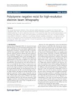
In Fig. 3 we show processed cross-section high-resolu-
tion transmission electron microscopy (HRTEM) images of
InAs submonolayer insertions in a GaAs matrux. The lat-
eral size of the InAs-rich domains formed at 480 °Cis
Fig. 1 Two phases with different values of intrinsic surface stress
(s
ij
) coexist on the surface. If the values s
ij
are different, there exists a
resulting elastic relaxation force F, which causes the lattice displace-
ment to reduce the energy of the system. Thus, formation of
boundaries becomes energetically favorable unless short-range
potential due to dangling bonds at the edges starts to play a role.
Thus, an optimal size of the island exists
Fig. 2 Equilibrium distribution of the number of atoms 2D islands.
The optimum island at T = 0 consists of N
0
= 625 atoms, and the
surface coverage is 0.1
Fig. 3 Processsed HRTEM image of 0.3 ML InAs deposit in a GaAs
matrix at 350 °C(a) and 480 °C(b)
Nanoscale Res Lett (2007) 2:417–429 419
123
close to 2–3 nm being in general agreement with the data
reported [26] for InAs submonolayer deposits on GaAs.
Deposition at lower temperature results in lateral sizes of
6–8 nm in a general agreement with theory.
As the localization energy of SML QDs is relatively
small, their stacking appears to be particularly important.
In Fig. 4 we show results of theoretic modeling of the
preferable arrangement of 2D-shaped islands in an elasti-
cally anisotropic media. A phase diagram of a double sheet
array of flat islands (right, Fig. 4) is shown. P is the ratio of
the force applied to buried islands in different directions, z
0
is the separation between the surface and the sheet of
buried islands, and D is the in-plane period. One can see
that for thinner spacers the growth occurs in predominantly
vertically correlated way, or in tilted arrangement. How-
ever, already at periods close to one half of the lateral
period, a transition to anticorrelated growth occurs [6, 30].
At larger spacer layer thicknesses, the correlated growth is
to dominate again, but at thicker spacers both the degree of
vertical alignment and the strength of electronic coupling
are dramatically reduced. Thus, vertically correlated
growth can be realized for SML QDs only at extremely thin
spacer layers.
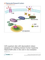
In Fig. 5 we show HRTEM (a) and processed HRTEM
(b) images of stacked InAs 0.5 ML islands inserted into a
1.2 nm GaAs layer in an Al
0.4
Ga
0.6
As matrix at 490 °C.
One can see from the image that the islands can be
observed only after image-processing, which reveals the
local lattice parameter in the vertical direction. One can see
that the islands do not form clearly vertically correlated
arrangement in the range of the spacer thicknesses chosen.
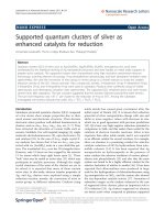
In spite of the fact that the lateral dimensions of SML
QDs are small and the related strain fields are weak, these
QDs can be revealed in plan-view TEM images, giving a
possibility to judge on their lateral density and relative
lateral sizes, revealed by the associated strain fields. Plan-
view TEM images of InAs 0.5 ML islands inserted into a
1.2 nm GaAs layer clad into an Al
x
Ga
1-x
As matrix and
stacked with a 5 nm periodicity are shown in Fig. 6 for (a)
Al
0.4
Ga
0.6
As matrix and (b) Al
0.6
Ga
0.4
As matrix. The lat-
eral density of SML QDs (*1–2 · 10
11
cm
À2
) is much
higher as compared to conventional Stranski-Krastanow
QDs deposited in similar conditions. The lateral sizes
(overestimated by strain fields) are significantly lower
(<10 nm), respectively.
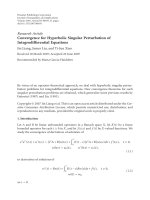
Anticorrelated arrangement of SML QDs was first
clearly revealed for CdSe QDs in a ZnSe matrix, as it is
shown in Fig. 7. Significant extension of the strain fields of
SML islands can be seen in Fig. 7b in the total lattice
displacement map, which evidences the 2D-like shifted flat
pedestal regions on top of the islands. Thus, the strain
gradient regions are mostly concentrated at the edges of
these pedestals, making the anti-correlated or tilted growth
arrangement favorable.
The actual distribution of the material in SML islands is
different from the nominal one due to the finite adatom
concentration on the surface and diffusion- and
Fig. 4 Modeling of the preferable arrangement of 2D-shaped islands
in an elastically-anisotropic media. A phase diagram of a double sheet
array of flat islands (left) is shown. P is the ratio of the force applied
to buried islands in different directions, z
0
is the separation between
the surface and the sheet of buried islands, and D is the in-plane
period. C- denotes correlated arrangement, A-anticorrelated and I-
intermediate (tilted) arrangement
Fig. 5 HRTEM (a) and processed HRTEM (b) images of stacked
InAs 0.5 ML islands inserted into a 1.2 nm GaAs layer in an
Al
0.4
Ga
0.6
As matrix. (b) shows a color-coded map of the local
increase of the lattice parameter in the vertical direction. Substrate
temperature is 490 °C
420 Nanoscale Res Lett (2007) 2:417–429
123
segregation-induced intermixing. In HRTEM experiments,
averaging effects along the HRTEM foil used in mea-
surements is taking place. Thus, careful comparison of
modeled and experimental results is needed to judge on
real material distribution. In Fig. 8 color-coded local lattice
parameter (a,c) and total lattice displacement maps mod-
eled for anticorrelated arrangement of 2D islands are
shown. By comparison of the experimental image in Fig. 7
with the modeling data in Fig. 8 and assuming significant
averaging due to the small lateral island size as compared
to the HRTEM foil (*15 nm), one may conclude that the
actual CdSe composition of SML islands is at or higher
than 40% and the adatom-induced ‘‘wetting layer’’ com-
position is 15–20% or lower.
Electronic Properties of Submonolayer QDs
Small lateral size of the islands formed by ultrathin inser-
tions raises a question on the applicability of QD model to
explain the properties of SML insertions. A clear signature
of QD states is observation of discrete luminescence lines
due to single QDs [28], which survive up to high
temperatures.
In Fig. 9 we show cathodoluminescence spectra of CdSe
QDs obtained using an approach of ultrasmall openings in
metal masks. This technique had been used to resolve
single QD emission lines up to high observation tempera-
tures and to calculate the density of the QDs. A series of
temperature dependent spectra of a single QD is displayed
in Fig. 9a. Increasing the temperature enhances the prob-
ability of phonon-related dephasing processes, causing
Lorentzian broadening of the lines above 50 K. For tem-
peratures above 110 K the lines are still clearly resolved in
the spectra while their wavelength overlap becomes more
pronounced. The peak energy of single lines and of their
overlap at higher temperatures followed the CdSe band-gap
dependence up to room temperature, evidencing the fact
that no change in the recombination mechanism took place
and the same QD radiative recombination mechanism
dominate at 300 K. A lineshape analysis showed that the
Fig. 6 InAs 0.5 ML islands
inserted into a 1.2 nm GaAs
layer clad into an Al
x
Ga
1-x
As
matrix and stacked with a 5 nm
period. (a)Al
0.4
Ga
0.6
As matrix
(b)Al
0.6
Ga
0.4
As matrix
Fig. 7 (a) <110> projection HRTEM image of a CdSe/ZnSe
submonolayer (SML) superlattice structure. (b) Color-coded maps
of the local lattice parameter in the vertical <001> direction and (c)
the total atom displacements with respect to the underlying ZnSe
layer plane for the same area
Nanoscale Res Lett (2007) 2:417–429 421
123
integrated intensity remained almost constant (see Fig. 9c)
up to and above 100 K, while the amplitude decreased
due to the dephasing-induced broadening. These obser-
vations suggest that thermal activation of QD excitons to
continuum states is negligible even at temperatures above
100 K.
Another unique possibility, which was first discovered
in SML QDs [29], and was later translated to SK QDs [32,
33] is a possibility to control polarization of the lumines-
cence of QD structures in edge geometry. Indeed, vertically
coupled growth results in strain and wavefunction modifi-
cations which favor unpolarized or even TM-polarized
emission in edge geometry, opposite to the case of
uncoupled QDs, always demonstrating TE-polarized
emission, similar to the case of compressively strained or
lattice-matched quantum wells.
In Fig. 10 we show color-coded maps of the local lattice
parameter for SML QDs stacked with 3 nm (top) and
1.5 nm (bottom) spacer layers. One can see from Fig. 10
that transition to thinner spacers is accompanied by a
remarkable change in the vertical correlation of the islands.
Vertically aligned chains become clearly visible.
In Fig. 11 linearly polarized photoluminescence (PL)
spectra of CdSe–ZnSe structures with 8, 3 and 1.5 nm
ZnSe spacers measured in edge geometry are shown. The
polarization changes from mostly TE for uncoupled islands
(8 nm spacers) to mostly TM (accompanied by a red shift)
for vertically coupled islands (1.5 nm spacers). The 3 nm
spacer sample shows emission from both types of islands.
Thus, formation of vertically correlated states is clearly
confirmed in photoluminescence studies, on top of
HRTEM results, evidencing the modification of the elec-
tronic spectrum of QDs.
It is also very important to note that the electron and
hole confinement in vertically coupled QDs is significantly
increased as compared to the wetting layer and matrix
continuum, further improving temperature stability of the
QD luminescence.
In the case of vertically correlated growth at very thin
spacer layers, the surface morphology of the (In,Ga)As
insertions becomes significantly affected, the dot size
increases, and a periodic interface corrugation occurs.
The thickness and compositional modulation are
revealed in this case in plan-view transmission electron
microscopy (TEM) images (see Fig. 12a, c). In the case of
anti-correlated or tilted arrangement of the islands, the
interfaces remain planar, while the compositional modu-
lation can be revealed in cross-section high-resolution
transmission electron microscopy and in cross-section
scanning tunneling microscopy (X-STM) [34]. In Fig. 13
we show a cross-section scanning tunneling microscopy
image of SML QD insertions in chemically sensitive
Fig. 8 Color-coded local lattice
parameter (a, c) and total lattice
displacement maps modeled for
anticorrelated arrangement of
2D islands: 4 ML Cd
X
Zn
1-X
Se
insertion (a, b) with
X
island
= 0.4, X
adatoms
= 0.2;
3MLCd
X
Zn
1-X
Se (c, d) with
X
island
=1,X
adatoms
=0
Fig. 9 (a) Emission spectra of an individual CdSe QD for different
temperatures. (b) Temperature dependent linewidth of individual QD
exciton lines. (c) Temperature dependent integrated intensities of
individual QD exciton lines
422 Nanoscale Res Lett (2007) 2:417–429
123
conditions. Gray contrast corresponds to InAs SML
regions, which are coupled into tilted chains. The tilted
arrangement was theoretically predicted [35] and later
observed for flat 2D-shaped QDs [36]. The horizontal lines
correspond to single monolayer planes and the overall
thickness of the insertion is *7 nm. Thus, the SML
deposition leads simultaneously to a significant lateral
compositional modulation and high QD density [34],
resulting in a high material and modal gain.
For ultrahigh-speed directly modulated VCSEL appli-
cations it is extremely important to create an active media,
which is capable to ultrahigh modal gain at extremely high
temperatures and current densities. The problem of con-
ventional QW active media is the step-like density of states
for intersuband transitions, which results in hole-burning
effects at high current densities and gain depletion due to
overheating. In spite of the fact that ultrahigh exciton
oscillator strength can be realized in absorption spectra of
QWs, the excitons do not play any positive role under the
lasing conditions. At first, the excitons can be partially
dissolved at room temperature. However, even in structures
made of II–VI materials, where the exciton oscillator
strength is high and the excitons dominate up to high
excitation densities and observation temperatures, the
predominant lasing mechanism is related to LO-phonon-
assisted excitonic gain, which is relatively weak, as it
comes from many-particle interactions (predominantly
including an exciton and two LO-phonons). At high tem-
peratures and excitation densities the excitons are heated
and have a significant in-plane k-vector, making the
Fig. 10 Color-coded maps of
the local lattice parameter for
SML QDs stacked with 3 nm
(top) and 1.5 nm(bottom) spacer
layers. The relative arrangement
of islands is shown
schematically in the right
figures in relation to edge
luminescence polarization axes
Fig. 11 Linearly polarized
photoluminescence (PL) of
structures with 8, 3 and 1.5 nm
spacers measured in edge
geometry. The polarization
changes from mostly TE for
uncoupled islands (8 nm
spacers) to mostly TM
(accompanied by a red shift) for
vertically coupled islands
(1.5 nm spacers). The 3 nm
spacer sample shows emission
from both types of islands. The
relative arrangement of islands
is shown schematically in the
right figures in relation to edge
luminescence polarization axes
Nanoscale Res Lett (2007) 2:417–429 423
123
probability of their zero-phonon radiative annihilation
negligibly low [5, 27, 28]. Already in narrow II–VI quan-
tum wells, however, the interface roughness can make a
zero-phonon scattering-assisted lasing mechanism domi-
nant. A truly excitonic gain can be realized, however, only
in QDs, where the excitons are fully confined. In practical
QD structures, at least an order of magnitude higher
material gain as compared to QWs at room temperature
was manifested, even in case of significantly inhomoge-
neously broadened ensembles (>kT). The problem of using
conventional S-K QDs in VCSELs originates, however,
from the fact that the sheet density of QDs is relatively low
*1–8 · 10
10
cm
À2
and the carriers can escape from QDs
at elevated temperatures populating the matrix and wetting
layer states. Increasing the density of QDs by stacking is
difficult due to the increased average strain in the structure
and the related formation of misfit dislocations. As oppo-
site, very small QDs formed by SML insertions can form
efficient confinement centers of ultrahigh density, which
can lift effectively the k-selection rule, but do not degrade
the structural quality of the system. Pure exctionic lasing
mechanism up to high temperatures and excitation densi-
ties can be realized on one side, while an ultrahigh density
of QDs can be achieved on the other. Thus, gain coeffi-
cients comparable to the absorption coefficients in narrow
QWs can be potentially, realized. To achieve this goal,
however, one needs to keep the lateral size of the localizing
insertions to be comparable or less than the effective
exciton radius in the narrow QWs (about 5–8 nm). The
confinement potential should be made as large as possible
to provide the strongest confinement of the localized
exciton with respect to the continuum states. The lateral
separation between the localizing centers should be suffi-
cient to prevent coupling of QD excitons to broad
minizones staying above 3–5 nm, depending on the con-
finement potential (the size inhomogeneity may reduce the
coupling even at very small average lateral separations). As
a result of the above consideration, the material arrange-
ment presented in Fig. 13 seems to be particularly
interesting for applications in VCSELs.
Thus, in the case of the particular SML QDs used for the
VCSEL structures processed and studied in this work, the
SML growth proceeded in a mode with ten 0.5 ML InAs
deposition cycles separated by 2.2 ML GaAs spacers at a
substrate temperature of 490 °C. 10 s growth interruptions
were introduced at the GaAs interfaces to ensure repro-
ducible surface morphology for the InAs nucleation. Three
sheets of stacked SML QD insertions separated by 13-nm-
thick GaAs spacer layers were used as an active region
[34].
In Fig. 14 we show photoluminescence (PL) and PL
excitation (PLE) spectra of the SML QD structure, used in
VCSELs, taken at 7 K. Two sharp peaks, separated by
12 meV with a full width at half maximum of *4–5 meV
are observed in the PL spectra. The peak at lower energy
dominates the spectra at low excitation densities (4 mW/
cm
2
), while the high-energy peak increases with higher
Fig. 12 Plan-view transmission electron microscopy (TEM) images
of submonolayer QDs: Thicknesses of the insertions and the
compostions are: (a) 5.4 nm, In
0.24
Al
0.26
Ga
0.48
As; (b) 7.8 nm,
In
0.19
Ga
0.81
As; (c) 5.4 nm In
0.24
Ga
0.76
As. Submonolayer deposition
is performed in 0.8 ML InAs cycles (a, c), or in 0.5 ML (b) cycles.
The characteristic feature size varies from 15–30 nm (a) to 5–15 nm
(b) and 40–60 nm (c). Depending on the AlAs and InAs composition
one can adjust the wavelength of SML QDs within 0.75–1.3 lm
Fig. 13 Empty state cross-section scanning tunneling microscopy
image of the SML QD insertion taken at low positive sample bias.
Ten cycles of 0.5 ML InAs deposition cycles separated by 2.2 ML
GaAs spacers at a substrate temperature of 490 °C has been
deposited. 2–3 nm-wide In-rich columns tilted by *35
o
with respect
to [001] direction are observed
424 Nanoscale Res Lett (2007) 2:417–429
123
excitation densities. PL excitation spectra evidence that
both peaks originate from the same quantum object. The
PLE spectra, detected at the lower energy peak reveals the
higher energy peak, indicating that both states originate in
the same quantum object. As the height of the SML
insertion is only *7 nm, the double-peak feature can’t be
explained by the light-to-heavy hole exciton splitting due
to the significant strain and quantum confinement-induced
separation between the two valence band states [37]. The
most natural assumption for the origin of the features is
ground and excited heavy-hole QD exciton states, similar
to the case of three-dimensional QDs [37].
Similarly, for the double-peak feature in the PLE spectra
at 1.43 and 1.49 eV light-hole-like ground and excited
exciton states might be responsible.
In Fig. 15 we show micro-PL spectra of the SML QDs
taken with an excitation spot size of *1 lm
2
. One can see
that the PL spectrum is composed of multiple sharp lines
originating from different SML QDs with narrow features
resolved at both low and at high photon energy side of the
spectrum [37]. The sharp emission lines are reproducible,
once the micro-PL spectrum is repeated for the same spot
(see gray line in Fig. 15). These sharp lines change, when
the excitation spot on the sample is moved and can’t be
attributed to noise fluctuations. Similar features have been
also revealed for the high-energy PL peak. Further studies
are presently under way to achieve better understanding of
the nature of the involved electronic states and optical
properties of this type of SML QDs used in the VCSELs
studied.
VCSEL Cavity Design
The radiative recombination probability of the dipole can
be changed by changing the effective refractive index of
the media to which the photon is emitted. Multilayer
media open dramatic possibilities in redistribution of the
oscillator strength, increase in the differential gain and
suppression of the parasitic modes. The easiest approach
to improve VCSEL device performance is to apply an
antiwaveguiding design [38] with the cavity region having
a smaller refractive index as compared to the average
refractive index of the distributed Bragg reflectors
(DBRs).
In conventional VCSELs, the cavity region is typically
composed of the material having a higher refractive index.
In this situation in-plane waveguide modes are possible. It
is well known that VCSEL structures behave as low-
threshold high-performance in-plane lasers, if processed in
stripe-laser geometry. Assuming a standard high-speed
oxide-confined VCSEL design with relatively small deep-
etched VCSEL mesa, two types of in-plane confined
modes, which do not penetrate into the DBRs, are possible.
High quality factor (Q) modes are associated with the
etched mesa, which is typically small enough to reduce the
parasitic capacitance. Low-Q modes are associated with the
oxide aperture [39]. As the VCSEL is operating under high
current densities, the absorbing regions of the mesa, which
are not electrically pumped by current injection become
transparent by photoexitation due to in-plane spontaneous
and stimulated emission.
These high Q modes behave as whispering gallery
modes in microdisc structures, or, in some sense, similar to
the modes existing in four-side facet-cleaved laser diodes.
High power density accumulated in these modes can dra-
matically reduce the radiative lifetime and prevents low-
threshold lasing for the VCSEL mode. Higher order high Q
1.35 1.40 1.45 1.50 1.55
).nu.bra(ytisn
etnI
Energy (eV)
T=7K
QD
excited state
E
GaAs
PL
PLE
QD
ground state
Fig. 14 Photoluminescence (PL) and PL excitation spectra of the
SML QD structure. The PL spectra are taken at excitation densities of
4 mW/cm
2
(solid line) and *1 kW/cm
2
(dash-dotted line). The PLE
spectrum is taken at 1.357 eV, which corresponds to the maximum of
the PL intensity
Fig. 15 Micro-PL spectra of the SML QD emission taken with an
excitation spot of *1 lm
2
at T = 7 K. The gray line is the part of the
PL spectrum repeated for the same excitation spot. The gray spectrum
is shifted for clarity. One can see that all the main features in the
spectra coincide
Nanoscale Res Lett (2007) 2:417–429 425
123
whispering gallery modes penetrate deep into the VCSEL
mesa up to the distance * R/n, where R is the radius of the
VCSEL mesa and n is the effective refractive index of the
waveguide medium [39].
The whispering gallery modes associated with the oxide
aperture is characterized by lower Q values due to the
lower effective refractive index step in the outer region
[39].
An approach to reduce such problems like radiative
leakage, gain depletion, self-pulsation, or even parasitic in-
plane lasing in VCSELs is the anti-waveguiding (AVC-
SEL) design, where no guided modes are possible for in-
plane light propagation (see Fig. 16). The intensity of the
guided mode is redistributed in this case towards tilted
emission, which has low overlap with the active region and
effectively leaks to the substrate. The AVCSEL concept is
different to AlAs-rich half-wave cavity, previously used for
creation of ultrahigh optical confinement oxide-confined
VCSELs [40]. The AlAs-rich half-wave cavity designs
may result in a low-loss in-plane mode with a significant
overlap with the active layer. The mode is confined in the
p-GaAs contact layer, which is sandwiched between the
AlAs cavity on one side, and the dielectric Bragg reflector
on the other. In the AVCSEL design such modes should be,
preferably, avoided.
Further suppression of the parasitic tilted modes is
possible in a multi-periodicity DBR VCSEL design, when
the tilted modes can be suppressed by a second DBR
periodicity.
Experimental Studies of 980 nm Sml QD Avcsels
Static Device Characteristics
The 980 nm VCSEL structures using InGaAs SML QDs,
[34] were realized in an antiwaveguiding design [38, 39]
with a high Al-content cavity and doped bottom and top
distributed Bragg reflectors with 32 and 19 pairs respec-
tively (see Fig. 16). A single AlAs-rich aperture layer,
being partially oxidized, was placed in a field intensity
node on top of the 3k/2 cavity. High speed and high-effi-
ciency devices with a co-planar layout were processed
using standard lithographic, metal deposition and dry
etching techniques. The selective oxidation procedure to
create the oxide apertures was performed under carefully
optimized conditions [34] to avoid formation of parasitic
precipitates causing strain, degradation and increasing
scattering loss in the devices.
Fig. 17 shows static continuous wave (cw) device
characteristics for a 5 lm aperture multimode laser. The
output power exceeds 10 mW at 20 °C; the differential
efficiency and threshold current are hardly dependent on
temperature over a very broad range.
Small Signal Modulation
For the small signal characterization the light was butt-
coupled into a *3 m 62.5 lm graded index multimode
fiber, which was connected to a 25 GHz frequency cali-
brated multimode photoreceiver (Discovery
Semiconductors DSC30 S). The small signal modulation as
well as the recording of the frequency dependent trans-
mission (S21) and reflection (S11) was done with a
calibrated HP 8722 C 40 GHz network analyzer. Fig-
ure 18 shows small signal modulation parameters under
continuous wave (cw) operation for a 6 lm SML QD-
VCSEL at 25 and 85 °C, obtained from fitting the three-
parameter transfer function with the unknown resonance
frequency f
res
, damping rate c and parasitic cutoff fre-
quency of the RC low-pass f
par
to the S21 modulation
response [41]. The maximum bandwidths (Fig. 10a) are 15
and 13 GHz, the modulation current efficiency factors are
4.6 and 5:6 GHz=
ffiffiffiffiffiffiffi
mA
p
, respectively. Due to a smaller
cavity-gain detuning at 85 °C for small currents, the
modulation efficiency here is higher. The maximum ther-
mally limited resonance frequency at 25 °C is close to
f
res
= 10 GHz, see Fig. 18b. The thermally limited modu-
lation bandwidth would be *15.5 GHz. Fig. 18c shows
the damping rate vs. square of the resonance frequency.
The K-factor is identical for both temperatures up to
medium resonance frequencies and currents. Its value
predicts an intrinsic bandwidth of f
damp
= 21 GHz. From
the different kink-points of the slope of the damping rate at
both temperatures the influence of the temperature depen-
dent differential gain on the damping rate can be inferred.
The electrical RC-limited bandwidth is f
par
= 12 GHz,
obtained from equivalent circuit fitting to the measured
S11-parameters. With negligible damping and no thermal
5.0 5.5
3.0
3.2
3.4
3.6
).nu.bra(ytisnetnI
Distance from substrate (µm)
xedniev
i
tcarf
e
R
Fig. 16 Refractive index and superimposed intensity distribution for
the central part of the SML QD-VCSEL
426 Nanoscale Res Lett (2007) 2:417–429
123
effects, this would result in a parasitic limited modulation
bandwidth of (2 + H3) · f
par
[42]. Damping is always
present and the maximum parasitic limit is only reached for
very high resonance frequencies of f
r
= H(5 + 3H3) · f
par
.
One can conclude, that the resonance frequency and thus
thermal effects dominate. Simulations of the transfer
function with different values for f
res
, c and f
par
also con-
firmed this condition. A small signal modulation bandwidth
of 12 GHz has been reported in [43] for edge emitting QD
lasers.
Large Signal Modulation
The same fibers and detector as for the small signal mod-
ulation experiments were used. Fig. 19a shows optical eye
diagrams for 20 Gb/s back-to-back NRZ 2
7
–1 PRBS
modulation at 25 and 85 °C. The bias current and modu-
lation voltage were kept constant at 13 mA and 0.8 V
p-p
for
this comparison. Both eyes are clearly open. The signal to
noise ratio (S/N) changed only from 5.9 at 25 °C to 4.3 at
85 °C, the extinction ratio was above 4.0 dB. Fig. 11b
shows the bit-error-rates (BER) also at 25 and 85 °C.
Except for the modulation voltage at 25 °Cof1.2V
p-p
, the
driving conditions were identical to the eye measurements.
To account for the required discriminator voltage of the
error detector, a 40 GHz amplifier was used after the
photoreceiver. The device operates error free with a
BER < 10
À12
and no error floor even for 85 ° C. The pen-
alty at 85 °C is only 1 dB compared to the back-to-back
error rate at 25 °C. As can be deduced from the error free
eye in Fig. 19aat25°C, an identical modulation voltage of
0.8 V
p-p
would have resulted in the same BER, but the
penalty at 85 °C compared to 25 °C would have been even
smaller. To the best of our knowledge this is the fastest
error free large signal modulation of any VCSEL at 85 °C.
20 Gb/s [3], [44] or faster [4] large signal modulation
experiments have been performed at lower temperatures,
but the high speed performance at 85 °C is crucial for most
short-distance optical interconnect applications.
Thus, we demonstrated 980 nm VCSELs based on a
triple stack of quantum dots, deposited in a submonolayer
growth mode, with a thermally limited, error free 20 Gb/s
direct modulated operation at 25 and 85 °C. In combina-
tion with their excellent static performance, i.e. high
external efficiency even at 85 °C, these devices demon-
strate the potential of this novel active material for
temperature stable ultra high speed VCSELs. At room
0
1
2
3
4
5
Aperture 5 µm
20
°
C
80
°
C
100
°
C
20
°
C
80
°
C
100
°
C
Power (mW)
Current (mA)
(a)
0.00
0.05
0.10
0.15
0.20
0.25
0.30
0.35
(b)
Wall-Plug Efficiency
Current (mA)
0
1
2
3
4
5
6
7
8
0
1
2
3
4
5
6
7
8
Fig. 17 Characteristics of a
multimode SML-QD-AVCSEL:
(a) L-U-I and (b) wall-plug
efficiency and threshold current
vs. temperature
Fig. 18 Small signal modulation parameters for a 6 lm SML QD-
VCSEL at 25 and 85 °C, obtained from fitting the modulation
response to the three-parameter transfer function: (a)—3 dB band-
width and (b) resonance frequency as a function of the square root of
the current above threshold, (c) damping rate vs. squared resonance
frequency. The maximum -3 dB bandwidth is 15 and 13 GHz,
respectively
Nanoscale Res Lett (2007) 2:417–429 427
123
temperature, it is possible to achieve 25 Gb/s transmission
(see Fig. 20) even both RC and photodetector response
limitations (*25 GHz) become evident.
To evaluate the ultimate time response of the device
relaxation oscillation studies have been performed. A sat-
uration relaxation oscillation frequency of 28 GHz was
derived (see Fig. 21). Thus, >40 Gb/s transmission is
possible in case if the device resistance is further reduced,
and an optimized heat dissipating VCSEL design [45]is
provided.
Conclusions
Development of novel types of QD media capable to
ultrahigh current densities without suffering from gain
saturation and lifetime degradation effects is a must to
realize ultrahigh-speed directly modulated high-tempera-
ture VCSELs. SML QDs provide such an opportunity. The
performance of SML QDs can be additionally enhanced by
properly engineered VCSEL design. A significant further
improvement in the performance of directly modulated
VCSEL can be expected with proper optimization of SML
QDs. Future work will also include wavelength adjustment
of SML QDs to 850 nm and 1300 nm spectral ranges.
Acknowledgment The authors appreciate support from the German
Ministry for Education and Research bmb+f (NanOp), the State of
Berlin (TOB), the SANDiE Network of Excellence of the European
Commission (NMP4-CT-2004–500101), NL-Nanosemiconductor
(Innolume) GmbH and Discovery Semiconductors Inc. NJ.
References
1. G.K. Cambron ‘‘The multimedia explosion: transforming the
physical layer’’ presented at the OFC/NFOEC 2006, March 5–10,
2006 Anaheim, California, USA
2. K.J. Ebeling, R. Michalzik, R. King, P. Schnitzer, D. Wieden-
mann, R. Ja
¨
ger, C. Jung, M. Grabherr, M. Miller, Proceedings of
the 24th European Conference on Optical Communication,
Madrid, Spain, 20–24 (IEEE, New York), vol. 3, (1998)
Fig. 19 (a) 20 Gb/s back-to-
back eye diagram for a 6 lm
SML QD-VCSEL at 25 and
85 °C without change of the
bias current and modulation
voltage and (b) bit-error-rate at
20 Gb/s back-to-back with 2
7
-1
PRBS at 25 and 85 °C for the
same bias current
Fig. 20 Eye diagram at 24 Gb/s of SML-QD VCSEL at 25 °C
Fig. 21 Relaxation oscillations in the SML QD VCSEL as a function
of bias voltage applied
428 Nanoscale Res Lett (2007) 2:417–429
123
3. F.E. Doany, L. Schares, C.L. Schow, C. Schuster, D.M. Kuchta,
P.K. Pepeljugoski et al., Proc. OFC/NFOEC 2006, OFA3 (2006)
4. N. Suzuki, H. Hatakeyama, K. Fukatsu, T. Anan, K. Yashiki, M.
Tsuji, Proc. OFC/NFOEC 2006, OFA4 (2006)
5. D. Bimberg, M. Grundmann, N.N. Ledentsov, Quantum Dot
Heterostructures. (Wiley, New York, 1998)
6. V. Shchukin, N.N. Ledentsov, D. Bimberg, Epitaxy of Nano-
structures, Springer Series in NanoScience and Technology. Vol.
XII (Springer, New York, 2004)
7. N.N. Ledentsov, V.M. Ustinov, A.Yu. Egorov, A.E. Zhukov,
M.V. Maximov, I.G. Tabatadze, P.S. Kop’ev, Semiconductors.
28, 832 (1994)
8. N. Kirstaedter, N.N. Ledentsov, M. Grundmann, D. Bimberg,
V.M. Ustinov, S.S. Ruvimov, M.V. Maximov, P.K. Kop’ev, Zh.I.
Alferov, U. Richter, P. Werner, U. Gosele, J. Heydenreich,
Electron. Lett. 30, 1416 (1994)
9. H. Shoji, K. Mukai, N. Ohtsuka, M. Sugawara, T. Uchida, H.
Ishikawa, Photonics Technol. Lett. 7, 1385 (1995)
10. N.N. Ledentsov, N. Kirstaedter, D. Bimberg, Photonics Technol.
Lett. 8, 1276 (1996)
11. H. Shoji, K. Mukai, T. Ohtsuka, M. Sugawara, T. Uchida, H.
Ishikawa, Photonics Technol. Lett. 8, 1277 (1996)
12. D.L. Huffaker, L.A. Graham, D.G. Deppe, Electronics Lett. 33,
1225 (1997)
13. J.A. Lott, N.N. Ledentsov, V.M. Ustinov, A.Yu. Egorov, A.E.
Zhukov, P.S. Kop’ev, Zh.I. Alferov, D. Bimberg, Electron. Lett.
33, 1150 (1997)
14. F. Hopfer, I. Kaiander, A. Lochmann, A. Mutig, S. Bognar, M.
Kuntz, U.W. Pohl, V.A. Haisler, D. Bimberg Appl. Phys. Lett.
89, 061105 (2006)
15. J.A. Lott, N.N. Ledentsov, V.M. Ustinov, N.A. Maleev, A.E.
Zhukov, A.R. Kovsh, M.V. Maximov, B.V. Volovik, Zh.I. Al-
ferov, D. Bimberg, Electron. Lett. 36, 1384 (2000)
16. M. Laemmlin, G. Fiol, M. Kuntz, F. Hopfer, A. Mutig, N.N.
Ledentsov, A.R. Kovsh, C. Schubert, A. Jacob, A. Umbach, D.
Bimberg, Physica Status Solidi (c). 3, 391 (2006)
17. N. Hatory, K. Otsubo, M. Ishida, T. Akiyama, Y. Nakata, H.
Ebe, S. Okumura, T. Yamamoto, M. Sugawara, Y. Arakawa,
Extended Abstract. The 30th European Conference on Optical
Communication, ECOC-2004, Stockholm, Sweden, 5–9 Sep-
tember 2004
18. Y.H. Chang, P.C. Peng, W.K. Tsai, G. Lin, F. Lai, R.S. Hsiao,
H.P. Yang, H.C. Yu, K.F. Lin, J.Y. Chi, S.C. Wang, H.C. Kuo,
Photonics Technol. Lett. 18, 847 (2006)
19. C. Ribbat, R. Sellin, M. Grundmann, D. Bimberg, N.A. Sobolev,
M.C. Carmo, Electron. Lett. 37, 174 (2001)
20. I. Krestnikov, D. Livshits, S. Mikhrin, A. Kozhukhov, A. Kovsh,
N. Ledentsov, A. Zhukov, Electron. Lett. 41, 1330 (2005)
21. O.B. Shchekin, J. Ahn, D.G. Deppe, Electron. Lett. 38, 712
(2002)
22. S.S. Mikhrin, A.R. Kovsh, I.L. Krestnikov, A.V. Kozhukhov,
D.A. Livshits, N.N. Ledentsov, Yu.M. Shernyakov, I.I. Novikov,
M.V. Maximov, V.M. Ustinov, Zh.I. Alferov, Semicond. Sci.
Technol. 20, 340 (2005)
23. V.I. Marchenko, Soviet Phys.—J. Exper. Theor. Phys. Lett. 33,
381 (1981)
24. M. Tsuchiya, J.M. Gaines, R.H. Yan, R.J. Simes, P.O. Holtz, L.A.
Coldren, P.M. Petroff, Phys. Rev. Lett. 62, 466 (1989)
25. O. Brandt, L. Tapfer, K. Ploog, R. Bierwolf, M. Hohenstein, F.
Phillipp, H. Lage, A. Heberle, Phys. Rev. B. 44, 8043 (1991)
26. V. Bressler-Hill, A. Lorke, S. Varma, P.M. Petroff, K. Pond,
W.H. Weinberg, Phys. Rev. B. 50, 8479 (1994)
27. N.N. Ledentsov, I.L. Krestnikov, M.V. Maximov, S.V. Ivanov,
S.L. Sorokin, P.S. Kopev, Zh.I. Alferov, D. Bimberg, N.N. Le-
dentsov, C.M. Sotomayor Torres, Appl. Phys. Lett. 69, 1343
(1996), ibid. 70, 2766 (1997)
28. I.L. Krestnikov, N.N. Ledentsov, A. Hoffmann, D. Bimberg,
Phys. Stat. Sol. (a). 183, 207 (2001)
29. I.L. Krestnikov, M. Straßburg, M. Caesar, A. Hoffmann, U.W.
Pohl, D. Bimberg, N.N. Ledentsov, P.S. Kop’ev, Zh.I. Alferov,
D. Litvinov, A. Rosenauer, D. Gerthsen, Phys. Rev. B. 60, 8695
(1999)
30. V.A. Shchukin, D. Bimberg, Rev. Mod. Phys. 71, 1125 (1999)
31. V.A. Shchukin, N.N. Ledentsov, A. Hoffmann, D. Bimberg, I.P.
Soshnikov, B.V. Volovik, V.M. Ustinov, D. Litvinov, D. Gerth-
sen, Phys. Stat. Sol. (b). 224(2), 503–508 (2001)
32. P. Yu, W. Langbein, K. Leosson, J.M. Hvam, N.N. Ledentsov D.
Bimberg, V.M. Ustinov, A.Yu. Egorov, A.E. Zhukov, A.F.
Tsatsulnikov, Yu.G. Musikhin, Phys. Rev. B. 60, 16680 (1999)
33. T. Kita, O. Wada, H. Ebe, Y. Nakata, M. Sugawara, Jpn. J. Appl.
Phys. Part 2 41, L1143 (2002)
34. F. Hopfer, A. Mutig, G. Fiol, M. Kuntz, V.A. Shchukin, V.A.
Haisler, T. Warming, E. Stock, S.S. Mikhrin, I.L. Krestnikov,
D.A. Livshits, A.R. Kovsh, C. Bornholdt, A. Lenz, H. Eisele, M.
Da
¨
hne, N.N. Ledentsov, D. Bimberg, J. Sel. Topics Quantum
Electron, in print
35. V.A. Shchukin, D. Bimberg, V.G. Malyshkin, N.N. Ledentsov,
Phys. Rev B. 57, 12262 (1998)
36. G. Springholz, V. Holy, M. Pinczolits, P. Mayer, V. Holy, G.
Bauer, H.H. Kang, L. Salamanca-Riba, Phys. Rev. Lett. 84, 4669
(2000)
37. O. Stier, M. Grundmann, D. Bimberg, Phys. Rev. B. 59, 5688
(1999)
38. N.N. Ledentsov, V. Shchukin, ‘‘Optoelectronic device based on
an antiwaveguiding cavity’’ United States Patent Application
20050226294
39. N.N. Ledentsov, F. Hopfer, A. Mutig, V.A. Shchukin, A.V. Sa-
vel’ev, G. Fiol, M. Kuntz, V.A. Haisler, T. Warming, E. Stock,
S.S. Mikhrin, A.R. Kovsh, C. Bornholdt, A. Lenz, H. Eisele, M.
Da
¨
hne, N.D. Zakharov, P. Werner, D. Bimberg Proc. SPIE Vol.
6468, 64681O, Physics and Simulation of Optoelectronic Devices
XV; M. Osinski, F. Henneberger, Y. Arakawa, eds. (2007)
40. D.L. Huffaker, J. Shin, D.G. Deppe, Electron. Lett. 30, 1946
(1994)
41. L.A. Coldren, S.W. Corzine, Diode Lasers and Photonic Inte-
grated Circuits, Wiley Series in Microwave and Optical
Engineering. vol. XXVI (Wiley, New York, 1995), p. 204
42. R. Stevens, R. Schatz, A. Lo
¨
vqvist, T. Aggerstam, C. Carlsson,
C.A. Barrios, S. Lourdudoss, M. Ghisoni, Proc. SPIE. 4286,71
(2001)
43. S.M. Kim, Y. Wang, M. Keever, J.S. Harris, IEEE Photon.
Technol. Lett. 16, 377 (2004)
44. P. Pepeljugoski, D. Kuchta, Y. Kwark, P. Pleunis, G. Kuyt, IEEE
Photon. Technol. Lett. 14, 717 (2002)
45. A.N. AL-Omari, G.P. Carey, S. Hallstein, J.P. Watson, G. Dang,
K.L. Lear, IEEE Photon. Technol. Lett. 18, 1225 (2006)
Nanoscale Res Lett (2007) 2:417–429 429
123