Báo cáo hóa học: " Excellent Field Emission Properties of Short Conical Carbon Nanotubes Prepared by Microwave Plasma Enhanced CVD Process" pot
Bạn đang xem bản rút gọn của tài liệu. Xem và tải ngay bản đầy đủ của tài liệu tại đây (481.06 KB, 6 trang )
NANO EXPRESS
Excellent Field Emission Properties of Short Conical Carbon
Nanotubes Prepared by Microwave Plasma Enhanced CVD
Process
Sanjay Kumar Srivastava Æ Vasant D. Vankar Æ
Vikram Kumar
Received: 15 November 2007 / Accepted: 22 November 2007 / Published online: 5 December 2007
Ó to the authors 2007
Abstract Randomly oriented short and low density con-
ical carbon nanotubes (CNTs) were prepared on Si
substrates by tubular microwave plasma enhanced chemi-
cal vapor deposition process at relatively low temperature
(350–550 °C) by judiciously controlling the microwave
power and growth time in C
2
H
2
+ NH
3
gas composition
and Fe catalyst. Both length as well as density of the CNTs
increased with increasing microwave power. CNTs con-
sisted of regular conical compartments stacked in such a
way that their outer diameter remained constant. Majority
of the nanotubes had a sharp conical tip (5–20 nm) while
its other side was either open or had a cone/pear-shaped
catalyst particle. The CNTs were highly crystalline and had
many open edges on the outer surface, particularly near the
joints of the two compartments. These films showed
excellent field emission characteristics. The best emission
was observed for a medium density film with the lowest
turn-on and threshold fields of 1.0 and 2.10 V/lm,
respectively. It is suggested that not only CNT tip but open
edges on the body also act as active emission sites in the
randomly oriented geometry of such periodic structures.
Keywords Carbon nanotubes Á CVD Á Microwave
plasma CVD Á Field emission Á Conical CNTs
Introduction
Carbon nanotubes (CNTs) [1] have attracted wide attention
both in the research and industrial communities because of
their unique structure and properties. In particular, field
electron emission from CNTs has been proposed to be one
of the most promising as far as its practical application is
concerned. This is because CNTs present many advantages
over conventional Spindt (Mo, Si, etc.) emitters [2] such as
(i) high chemical stability (resistance to oxidation or other
chemical species) and high mechanical strength (Young’s
modulus *1 TPa), (ii) high melting point (*3,550 °C)
and reasonable conductivity (resistivity *10
-7
Xm), (iii)
high aspect ratio ([1,000) with very small tip radius to
greatly enhance the local electric field, and (iv) easy and
low cost production [3].
The potential of CNTs for field emission (FE) was first
reported in 1995. FE from an isolated single multiwalled
CNT (MWNT) was first observed by Rinzler et al. [4] and
that from a MWNT film was reported by de Heer et al. [5].
Since then a number of experimental studies on FE aspects
of both MWNTs [6–16] and single-walled CNTs [17, 18]
grown by different processes such as arc discharge and
various versions of chemical vapor deposition (CVD) both
with and without plasma have been investigated. Many
parameters such as density, length of CNTs, spacing
between neighboring nanotubes, open/closed tips, presence
of adsorbates, metal particles, etc., have been reported to
affect the FE characteristics of CNT films. Carbon nano-
structures other than CNTs, such as carbon nanofibers
(CNFs) [19, 20], carbon nanocones (CNCs) [21, 22], car-
bon nanosheets/nanowalls [23, 24], etc., are also promising
material structure as field emitters. Recently, there have
been continuous efforts on growth of one-dimensional
carbon nanostructures with a very sharp tip structure
S. K. Srivastava (&) Á V. Kumar
Electronic Materials Division, National Physical Laboratory,
Dr. K.S. Krishnan Marg, Pusa, New Delhi 110012, India
e-mail:
V. D. Vankar
Department of Physics, Thin Film Laboratory, Indian Institute
of Technology Delhi, Hauz Khas, New Delhi 110016, India
123
Nanoscale Res Lett (2008) 3:25–30
DOI 10.1007/s11671-007-9109-x
because it can enhance the FE characteristics significantly
[25–28]. Low density of such structures is indispensable
for FE due to the screening effect [11–15]. There have been
few studies on the role of length, density/spacing between
CNTs on the FE characteristics of CNT films [12–15].
However, most of them are for the vertically aligned CNTs
and there are very limited related investigations on the
randomly oriented CNTs [10, 11]. The structural charac-
teristic of the CNTs is critical for FE and is not discussed in
any of the above reports. This is important because CNTs
prepared by low temperature plasma CVD process have
many structural defects. For example, CNTs prepared by
PECVD process using any hydrocarbon and NH
3
or N
2
generally have bamboo-structure popularly known as
bamboo-shaped CNTs (BS-CNTs) [29–31]. Hence the
motivation of the present study was to grow CNTs films of
varying density and length and co-relate their structural and
FE characteristics.
In this article, films having randomly oriented short and
cone-shaped CNTs have been grown on Si substrates by
tubular MPECVD process at relatively low temperature
through judicious control over the process parameters such
as microwave power and growth time. Iron (Fe) thin films
deposited on Si substrates were used as the catalyst.
Acetylene (C
2
H
2
) and NH
3
were used as feed and dilution
gases, respectively. The field emission measurements
showed that they had excellent emission characteristics
compared to long and high-density BS-CNT films. It is
suggested that not only nanotube tips but open edges on the
body also act as active emission sites in the randomly
oriented geometry of these structures giving enhanced
emission characteristics.
Experimental
Carbon films were deposited by tubular MPECVD process
on p-Si (100) substrates. The details of the experimental set
up is described elsewhere [23]. In brief, tubular MPECVD
system is equipped with a 1.2 kW, 2.45 GHz microwave
source and a traverse rectangular wave-guide to couple the
microwave to a tubular quartz tube for generating the
plasma. No additional heater was used for substrate heat-
ing. It was heated directly by the plasma. The substrate was
placed on a quartz holder that was fully electrically insu-
lated and the substrate was fully immersed in the plasma
zone. No additional substrate biasing of the substrate was
made. Thin films of Fe *10 nm were deposited on
chemically cleaned Si wafers by thermal evaporation
technique at a base pressure of 2.0 9 10
-6
Torr and no
buffer layer was used between Fe film and Si substrates.
Fe-coated Si substrates were then loaded into the reactor
chamber for growth process. Growth process includes the
two steps: (i) pretreatment of Fe film in NH
3
plasma fol-
lowed by (ii) introduction of C
2
H
2
for carbon film
deposition. The pretreatment of Fe films had three main
objectives: (i) heating the substrate to the desired growth
temperature, (ii) etching of Fe film by active plasma spe-
cies, and (iii) conversion of the Fe film into Fe
nanoparticles needed for CNTs nucleation and growth. The
Fe films were pretreated in NH
3
plasma for 10 min at input
microwave powers of 300–450 W, operating pressure of
5 Torr and with NH
3
flow rate of 40 sccm. CNT films were
deposited at different microwave power varying from 300
to 450 W for a fixed C
2
H
2
/NH
3
flow rate ratio of 20/40 and
a pressure of 5 Torr for 3 min. Under these conditions,
substrate temperature varied in the range of 350–550 °C.
Scanning electron microscope (SEM) (LEO 435 VP)
operating at 15 kV was used for surface morphological
features of the films. Transmission electron microscope
(TEM) (Philips, CM 12) operating at 100 kV and high-
resolution TEM (HRTEM) (TECNAI 20UT) was used for
structural analysis of CNTs. The process of TEM specimen
preparation is described in our previous article [29]. Field
emission measurements were carried by planar diode
assembly at a base pressure of *2.0 9 10
-6
Torr [23].
Spacing between electrodes (d) was kept *300 lm. FE
current was measured with increasing voltage. Emission
current density was calculated by dividing the emission
current with the exposed area of the sample [32].
Results and Discussion
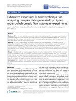
Figure 1 shows the SEM micrographs of samples deposited
at microwave power of 300, 350, 400, and 450 W (named
as sample 1, sample 2, sample 3, and sample 4, respec-
tively). It is clearly seen that no nanotube is observed for
sample 1 (Fig. 1a) and highly magnified image as shown in
the inset shows that nanotubes remain in their nucleation
stage. Very short length and low density of nanotubes is
observed in sample 2 (Fig. 1b). However, for samples 3
and 4, density and length increased significantly as shown
in Fig. 1c and d, respectively. Almost 50% of the area is
covered by CNTs and rest is covered by either catalytic
nanoparticles (bright contrast) or very short nanotubes. In
case of sample 4, almost whole area is covered with
nanotubes. The length and density of the CNTs estimated
by SEM study for these samples are given in Table 1. Both
the length and density of CNTs increased with increasing
microwave power. It is clear that large density of catalytic
nanoparticles is formed after NH
3
plasma pretreatment.
These catalytic particles seed the nucleation and growth of
nanotubes after C
2
H
2
introduction in the plasma. Each
nanotube has a catalyst nanoparticle mostly in the base
region, which clearly indicates that the growth is catalytic.
26 Nanoscale Res Lett (2008) 3:25–30
123
CNTs have generally conical shape as one shown in the
inset of Fig. 1b. At low microwave power, the plasma
density is low and hence slow rate of carbon supply to the
catalyst particles is expected. The substrate temperature is
also low since it is plasma dependent in the present
geometry and hence slow growth rate. Consequently, very
short length and low density CNTs are observed at low
input microwave power. With increase in microwave
power both plasma density and substrate temperature
increase, resulting more number of CNTs nucleation and
growth. CNTs of varying length are observed due to
different catalyst particle sizes [33].
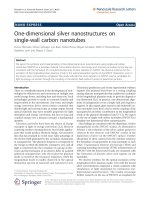
These samples were examined by TEM for determina-
tion of length, diameter, and internal structure of CNTs.
Representative TEM micrograph of the short length CNTs
is shown in Fig. 2a. It is clearly seen that CNTs consist of
regular and very short conical compartments stacked over
each other. The maximum length of CNTs was observed to
be *3 lm and the shortest nanotube observed by TEM
was *500 nm. The outer diameter of these nanotubes
varied in the range of 30–70 nm. It is to be noticed that
these short CNTs have very sharp tips of diameter in the
range of 5–20 nm. In general, tip diameter was estimated to
be approximately one-fourth of the outer diameter of the
tube body. Representative TEM micrograph showing full-
length view of such very short conical nanotube is shown
in Fig. 2b. The highly magnified view of nanotube tip is
shown in Fig. 2c. Clearly the wall thickness in the tip
compartment is very less compared to that in the preceding
compartments. The wall thickness is the maximum at the
joint of two compartments and it decreases gradually
toward the middle of a particular compartment and con-
tinues till the beginning of the next compartment. Each
compartment is of an almost equal length except the tip
one. The conical compartments are stacked in such a way
that total outer diameter of the tube body remains almost
constant. The other side of the tube is either open or has a
cone/pear-shaped catalytic particle (Fig. 2a, b). This side is
definitely the base of the conical CNTs. Therefore, the
growth of short conical CNTs in present study is governed
by the base growth mode [34]. The short CNTs are highly
crystalline as observed by HRTEM micrograph shown in
Fig. 2d. Compartments consist of parallel planes with an
inter-planar spacing of *0.34 nm. Because of the conical
shape, these walls are inclined toward the tube axis making
an acute angle of *5–6° in general. However, in some
Fig. 1 SEM micrographs of
CNT samples deposited at
different microwave power (a)
sample 1, (b) sample 2, (c)
sample 3, and (d) sample 4. The
magnified views of (a) and (b)
are shown in the respective
insets
Table 1 Comparison of microstructural features (such as length,
density) and field emission parameters (E
to
, E
th
, and b) of samples 2,
3, and 4
Sample Length
(lm)
Density
(910
7
cm
-2
)
E
to
(V/lm)
E
th
(V/lm)
b
2 0.5–0.8 *6 2.67 – 2528
3 0.5–1.5 *20 1.60 2.75 6953
4 1.5–3.0 *35 1.00 2.10 15724
Note: E
to
is the macroscopic field required for emission current
density of 10 lA/cm
2
, and E
th
is the field for emission current density
of 1 mA/cm
2
Nanoscale Res Lett (2008) 3:25–30 27
123
tubes this angle was observed to be *10°. Clearly, the
number of walls is maximum at the joint of two compart-
ments and minimum near the middle of the compartment. It
is to be noticed that there are many open edges on the outer
surface of the tube as indicated by arrows in Fig 2d. This is
attributed to their periodic structure and the stacking
arrangement of constituent compartment walls.
The growth mechanism of such periodic structure with a
sharp conical tip has been discussed in our previous article
[29], where it is suggested that nitrogen and atomic
hydrogen plays a significant role in the formation of
compartmentalized structure. It is shown by in situ optical
emission spectroscopy that high concentration of CN and H
species present in the NH
3
+ C
2
H
2
plasma facilitate the
growth of BS-CNTs [29]. The periodic appearance of
conical structure in one tube is supposed to be due to
periodic precipitation of the graphite sheets on the top
surface of the catalyst particle under steady state. The
catalyst particles were in quasi-liquid state during growth
and the high surface energy of the precipitating graphite
layers moulded the particles to acquire the stable minimum
energy configuration and hence the conical shape. The
growth of highly crystalline CNTs at relatively low tem-
perature could be due to high-density plasma. The plasma
not only ionizes the gas but also causes a local surface
heating [35]. Consequently, by this method growth tem-
perature could be greatly decreased compared to other non-
plasma CVD processes. In addition, a small concentration
of nitrogen doping is also reported in the compartmental-
ized CNT films [32]. It is also suggested that dangling
bonds in the open edges of such periodic structure may be
terminated by atomic hydrogen [36, 37].
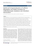
Figure 3a shows the comparative emission current
density (J) vs. macroscopic field (E) of samples 2, 3, and 4.
No significant emission current was observed from sample
1. The emission measurements were carried out for two
cycles with increasing and decreasing fields. Repeatable
emission data were observed during both the cycles for the
three samples. The comparative FE parameters such as
turn-on (E
to
) and threshold (E
th
) fields of these samples are
given in Table 1. This shows that emission performance
improves with increasing CNTs density and length. Sample
Fig. 2 TEM micrographs of
short conical CNTs (a) low
magnification image,
(b) magnified view of the
shortest conical CNTs,
(c) highly magnified view of tip,
and (d) typical HRTEM image
of a conical CNT
28 Nanoscale Res Lett (2008) 3:25–30
123
4 has the lowest E
to
and E
th
values. This is because number
of emission sites increases with increasing both length and
density of CNTs. However, very high density ([10
9
cm
-2
)
and longer (*10–15 lm) randomly oriented or vertically
aligned CNT (with similar structure) films had poor
emission characteristics than that of sample 4 [32], which
could be due to screening effect. This suggests that sample
4 has the optimum combination of length and density of
conical periodic structured CNTs in random orientation
configuration for the best emission.
Field emission is usually analyzed using Fowler–Nord-
heim (F–N) theory, according to which emission current
density is dependent on the local electric field (E
loc
) and
chemical state (i.e. work function, /) of the emitter tip as
J µ (E
2
loc
//) exp(-B/
3/2
/E
loc
) where B = 6.83 9 10
9
VeV
-3/2
m
-1
. The local field E
loc
is related to the macro-
scopic field (E) by geometrical enhancement factor (b)as
E
loc
= bE. The b can be determined experimentally from
the slope (S
F–N
) of ln(I/V
2
) vs. 1/V plot as b =-B/
3/2
d/S
F–N
, provided / is known. In case of CNT films,
emission occurs from multiple emitters and an integrated
current is measured. There could be lot of variations in
local fields due to various geometries of the emitters. Also,
work function of each emitter is not necessarily same. This
makes the exact analysis of field emission characteristics of
CNT films difficult.
The F–N plots for the three samples are given in Fig. 3b.
Interestingly single slope behavior is observed for all the
samples in contrast to our high-density BS-CNTs films
[32]. This is attributed to their lower density, which over-
comes the field screening effect and interaction among
neighboring CNTs [11, 14]. The geometrical enhancement
factors determined from slopes of the F–N plots assuming
/ = 5 eV, are given Table 1. These are 2,528, 6,953, and
15,724 for samples 2, 3, and 4, respectively. Such a high
field enhancement factor is accounted for the sharp tip and
open edges on the surface of CNTs [9, 17]. In this calcu-
lation, the / of CNTs is assumed as a constant, which is
known to be strongly dependent on several factors such as
structure/defects (e.g. capped, open, presence of metal
particles, etc.) of CNTs [38], and surface states. As an
example nitrogen incorporated in CNTs significantly
reduces the work function [39] and hydrogen saturated
surface (open edges terminated by hydrogen atoms) have
much lower values than that of graphite (*5 eV) [40]. The
exact experimental measurement of the work function for
CNTs, especially in film form, is complicated [41].
Therefore, the enhancement factor determined by F–N
plots is not truly correct and yields relatively higher values
[39]. Hence, the enhanced FE characteristics of short
conical CNT films should be attributed to the following: (i)
an optimum length and density combination to overcome
screening effect, (ii) sharp closed tips, and (iii) open edges
on the outer surface of CNTs which enhance the local field.
These open edges also act as additional emission sites [42].
In addition, other favorable conditions for enhanced
emission of such periodic structured conical CNTs could
be: (a) N doping in CNTs, which can increase the local
density of states near the Fermi level [43], (b) hydrogen
saturation of open edges on the surface which also decrease
the effective work function. It is also important to note that
no significant emission current was observed from sample
1 in the measurement range. This confirmed that the cat-
alytic particles lying on the substrate had no contribution
and emission occurred from CNTs only.
The field emission stability was also tested as in case of
high density BS-CNTs [32]. These films also showed stable
emission current with an average fluctuation of *2% and
small decrease of *2% emission current was observed for
sample 4 after continuous operation of 20 h. No significant
0.000 0.005 0.010 0.015
-34
-32
-30
-28
-26
-24
-22
-20
(b)
S
F-N
= -1450
S
F-N
= -3279
S
F-N
= -9019
V/I(nL
2
)
1/V
Sample 2
Sample 3
Sample 4
0.0 0.5 1.0 1.5 2.0 2.5 3.0 3.5 4.0
0
500
1000
1500
2000
2500
3000
3500
(a)
(J
µ
mc/A
2
)
E (V/µm)
Sample 2
Sample 3
Sample 4
Fig. 3 (a) Emission current density (J) vs. macroscopic electric field
(E) of samples 2, 3, and 4. (b) F–N plots of sample 2, sample 3, and
sample 4
Nanoscale Res Lett (2008) 3:25–30 29
123
change in the morphology of the films was observed after
such emission performance tests.
Conclusions
Films containing randomly oriented conical CNTs with
varying length and density were grown on Si substrates by
MPECVD process at relatively low temperature by judi-
cious control of the process parameters such as microwave
power and growth time. The CNTs have periodic com-
partmentalized structure with a sharp conical tip and many
open edges on the body. These films have superior emis-
sion characteristics compared to high density vertically
aligned or randomly oriented BS-CNT films. Lower den-
sity, sharp tips, defective body structure, and random
orientation of CNTs have been suggested for the enhanced
emission performance of these samples. It is known that
there is a strong correlation between the density and length
of aligned CNTs, where emission dominantly occurs from
the tip region, for stable and high emission current density
at low fields. However, for periodic structures like this,
where emission can also occur from the body regions,
controlling their length, density, and structure with the help
of growth parameters would be very useful for field
emission perspectives.
Acknowledgments One of the authors (S. K. Srivastava) is thankful
to Dr. D. V. Sridhar Rao, DMRL, Hyderabad, for his assistance in
HRTEM analysis of the samples.
References
1. S. Iijima, Nature 354, 56 (1991)
2. C.A. Spindt, J. Appl. Phys. 39, 3504 (1968)
3. P. Gro
¨
ning, L. Nilsson, P. Ruffieux, R. Clergereaux, O. Gro
¨
ning,
in Encyclopedia of Nanoscience and Nanotechnology, vol. 1, ed.
by H.S. Nalwa (American Scientific Publishers, 2004), p. 547
4. A.G. Rinzler, J.H. Hafner, P. Nikolaev, L. Lou, S.G. Kim, D.
Tomanek, P. Nordlander, D.T. Colbert, R.E. Smalley, Science
269, 1550 (1995)
5. W.A. de Heer, A. Cha
ˆ
telain, D. Ugarte, Science 270, 1179 (1995)
6. P.G. Collins, A. Zettl, Phys. Rev. B 55, 9391 (1997)
7. J.M. Bonard, F. Maier, T. Stoeckli, A. Chatelain, W.A. de Heer,
J.P. Salvetat, L. Forro, Ultramicroscopy 73, 7 (1998)
8. S. Fan, M.G. Chapline, N.R. Franklin, T.W. Tombler, A.M.
Cassell, H. Dai, Science 283, 512 (1999)
9. Y. Saito, S. Uemura, Carbon 38, 169 (2000)
10. O. Groning, O.M. Kuttel, Ch. Emmenegger, P. Groning,
L. Schlapbach, J. Vac. Sci. Technol. B 18(2), 665 (2000)
11. L. Nilsson, O. Groening, C. Emmenegger, O. Kuettel, E. Schaller,
L. Schlapbach, H. Kind, J.M. Bonard, K. Kern, Appl. Phys. Lett.
76, 2071 (2000)
12. M. Chhowalla, C. Ducati, N.L. Rupesinghe, K.B.K. Teo, G.A.J.
Amaratunga, Appl. Phys. Lett. 79, 2079 (2001)
13. J.S. Suh, K.S. Jeong, S. Lee, I. Han, Appl. Phys. Lett. 80, 2392
(2002)
14. K.B.K. Teo, M. Chhowalla, G.A.J. Amaratunga, W.I. Milne,
G. Pirio, P. Legagneux, F. Wyczisk, D. Pribat, D.G. Hasko, Appl.
Phys. Lett. 80, 2011 (2002)
15. S.H. Jo, Y. Tu, Z.P. Huang, D.L. Carnahan, D.Z. Wang, Z.F. Ren,
Appl. Phys. Lett. 82, 3520 (2003)
16. R.B. Rakhi, K. Sethupathi, S. Ramaprabhu, Nanoscale Res. Lett.
2, 331 (2007)
17. J M. Bonard, J P. Salvetat, T. Stockli, W.A. de Heer, L. Forro,
A. Cha
ˆ
telain, Appl. Phys. Lett. 73, 918 (1998)
18. W. Zhu, C. Bower, O. Zhou, G. Kochanski, S. Jin, Appl. Phys.
Lett. 75, 873 (1999)
19. C.H. Weng, K.C. Leou, H.W. Wei, Z.Y. Juang, M.T. Wei, C.H.
Tung, C.H. Tsai, Appl. Phys. Lett. 85, 4732 (2004)
20. Sk.F. Ahmad, S. Das, M.K. Mitra, K.K. Chattopadhyay, Appl.
Surf. Sci. 254, 610 (2007)
21. V.I. Merkulov, A.V. Melechko, M.A. Guillorn, D.H. Lowndes,
M.L. Simpson, Chem. Phys. Lett. 350, 381 (2001)
22. C.L. Tsai, C.F. Chen, L.K. Wu, Appl. Phys. Lett. 81, 721 (2002)
23. S.K. Srivastava, A.K. Shukla, V.D. Vankar, V. Kumar, Thin
Solid Films 492, 124 (2005)
24. Y. Wu, B. Yang, B. Zong, H. Sun, Z. Shen, Y. Feng, J. Mater.
Chem. 14, 469 (2004)
25. C.J. Huang, Y.K. Chih, J. Hwang, A.P. Lee, C.S. Kou, J. Appl.
Phys. 94
, 67 (2003)
26. L H. Chen, J.F. AuBuchon, A. Gapin, C. Daraio, P. Bandaru,
S. Jin, D.W. Kim, I.K. Yoo, C.M. Wang, Appl. Phys. Lett. 85,
5373 (2004)
27. C.J. Huang, C.M. Yeh, M.Y. Chen, J. Hwang, C.S. Kou,
J. Electrochem. Soc. 153(1), H15–H17 (2006)
28. X. Sun, R. Li, B. Stansfield, J P. Dodelet, G. Me
`
nard, S. De
`
silets,
Carbon 45, 732 (2007)
29. S.K. Srivastava, V.D. Vankar, V. Kumar, Thin Solid Films 515,
1552 (2006)
30. X. Ma, E.G. Wang, Appl. Phys. Lett. 78, 978 (2001)
31. J.W. Jang, C.E. Lee, S.C. Lyu, T.J. Lee, C.J. Lee, Appl. Phys.
Lett. 84, 2877 (2004)
32. S.K. Srivastava, D.V. Sridhar Rao, V.D. Vankar, V. Kumar, Thin
Solid Films 515, 1851 (2006)
33. S. Hofmann, M. Cantoro, B. Kleinsorge, C. Casiraghi, A. Parvez,
J. Robertson, C. Ducati, J. Appl. Phys. 98, 034308 (2005)
34. R.T.K. Baker, Carbon. 27, 315 (1989)
35. K.B.K. Teo, D.B. Hash, R.G. Lacerda, N.L. Rupeshinghe,
M.S. Bell, S.H. Dalal, D. Bose, T.R. Govindan, B.A. Cruden,
M. Chhowalla, G.A.J. Amaratunga, M. Meyyappan, W.I. Milne,
Nano Lett. 5, 921 (2004)
36. P.E. Nolan, D.C. Lynch, A.H. Cutler, J. Phys. Chem. B 102, 4165
(1998)
37. L. Delzeit, I. McAninch, B.A. Cruden, D. Hash, B. Chen, J. Han,
M. Meyyappan, J. Appl. Phys. 91, 9027 (2002)
38. Z. Xu, X.D. Bai, E.G. Wang, Z.L. Wang, Appl. Phys. Lett. 87,
163106 (2005)
39. J. Robertson, J. Vac. Sci. Technol. B 17, 659 (1999)
40. C.Y. Zhi, X.D. Bai, E.G. Wang, Appl. Phys. Lett. 81, 1690 (2002)
41. Z.P. Huang, Y. Tu, D.L. Carnahan, Z.F. Ren, in Encyclopedia of
Nanoscience and Nanotechnology, vol. 1, ed. by H.S. Nalwa
(American Scientific Publishers, 2004), p. 401
42. Y. Chen, D.T. Shaw, L. Guo, Appl. Phys. Lett. 76, 2469 (2000)
43. R. Sen, B.C. Satishkumar, A. Govindaraj, K.R. Harikumar,
G. Rainja, J.P. Zhang, A.K. Cheetham, C.N.R. Rao, Chem. Phys.
Lett. 287, 671 (1998)
30 Nanoscale Res Lett (2008) 3:25–30
123