Báo cáo hóa học: " Regenerative Relaying: Relay Selection and Asymptotic Capacity" pptx
Bạn đang xem bản rút gọn của tài liệu. Xem và tải ngay bản đầy đủ của tài liệu tại đây (831.47 KB, 12 trang )
Hindawi Publishing Corporation
EURASIP Journal on Wireless Communications and Networking
Volume 2007, Article ID 21093, 12 pages
doi:10.1155/2007/21093
Research Article
Distributed Antenna Channels with Regenerative Relaying:
Relay Selection and Asymptotic Capacity
Aitor del Coso and Christian Ibars
Centre Tecnol
`
ogic de Telecomunicacions de Catalunya (CTTC), Av. Canal Ol
`
ımpic, Castelldefels, Spain
Received 15 November 2006; Accepted 3 September 2007
Recommended by Monica Navarro
Multiple-input-multiple-output (MIMO) techniques have been widely proposed as a means to improve capacity and reliability
of wireless channels, and have become the most promising technology for next generation networks. However, their practical
deployment in current wireless devices is severely affected by antenna correlation, which reduces their impact on performance.
One approach to solve this limitation is relaying diversity. In relay channels, a set of N wireless nodes aids a source-destination
communication by relaying the source data, thus creating a distributed antenna array with uncorrelated path gains. In this paper,
we study this multiple relay channel (MRC) following a decode-and-forward (D&F) strategy (i.e., regenerative forwarding), and
derive its achievable rate under AWGN. A half-duplex constraint on relays is assumed, as well as distributed channel knowledge
at both transmitter and receiver sides of the communication. For this channel, we obtain the optimum relay selection algorithm
and the optimum power allocation within the network so that the transmission rate is maximized. Likewise, we bound the ergodic
performance of the achievable rate and derive its asymptotic behavior in the number of relays. Results show that the achievable rate
of regenerative MRC grows as the logarithm of the Lambert W function of the total number of relays, that is, C
= log
2
(W
0
(N)).
Therefore, D&F relaying, cannot achieve the capacity of actual MISO channels.
Copyright © 2007 A. del Coso and C. Ibars. This is an open access article distributed under the Creative Commons Attribution
License, which permits unrestricted use, distribution, and reproduction in any medium, provided the original work is properly
cited.
1. INTRODUCTION
Current wireless applications demand an ever-increasing
transmission capacity and highly reliable communications.
Voice transmission, video broadcasting, and web brows-
ing require wire-like channel conditions that the wireless
medium still cannot support. In particular, channel impair-
ments, namely, path loss and multipath fading do not al-
low wireless channels to reach the necessary rate and ro-
bustness expected for next generation systems. Recently, a
wide range of multiple antenna techniques have been pro-
posed to overcome these channel limitations [1–4]; however,
the deployment of multiple transmit and/or receive antennas
on the wireless nodes is not always possible or worthwhile.
For these cases, the most suitable technique to take advan-
tage of spatial diversity is node cooperation and relay channels
[5, 6].
Relay channels consist of single source-destination pairs
aided in their communications by a set of wireless relay nodes
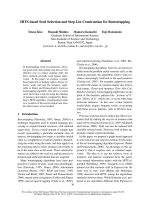
that creates a distributed antenna array (see Figure 1). The
relay nodes can be either infrastructure nodes, placed by the
service provider in order to enhance coverage and rate [7], or
a set of network users that cooperate with the source, while
having own data to transmit [8]. Relay-based architectures
have been shown to improve capacity, diversity, and delay
of wireless channels when properly allocating network re-
sources, and have become a key technique for the evolution
of wireless communications [9].
Background
The use of relays to increase the achievable rate of point-to-
point transmissions was initially proposed by Cover and El
Gamal in [10]. Motivated by this work, many relaying tech-
niques have been recently studied, which can be classified,
based on their forwarding strategy and required processing at
the relay nodes, as regenerative relaying and nonregenerative
relaying [5, 11]. The former assumes that relay nodes decode
the source information, prior to reencoding and sending it to
destination [12, 13]. On the other hand, with the latter, relay
nodes transform and retransmit their received signals but do
not decode them [14–16].
2 EURASIP Journal on Wireless Communications and Networking
Dec./enc.
Relay 1
Z
1
1
Y
1
1
X
2
1
(w)
b
1
c
1
X
1
s
(w)
X
2
s
(w)
a
.
.
.
.
.
.
Z
1
d
Z
2
d
Y
1
d
Y
2
d
Decoder
w
Destination
Encoder
Source
w
b
N
c
N
Z
1
N
Y
1
N
Dec./enc.
Relay N
X
2
N
(w)
Time slot 1: s
−→ N ,d Time slot 2: s, N −→ d
t
Figure 1: Half-duplex regenerative multiple relay channel with N parallel relays.
Regenerative relaying was initially presented in [10, The-
orem 1] for a single-relay channel, and consists of relay nodes
decoding the source data and transmitting it to destination,
ideally without errors. Such signal regeneration allows for co-
operative coherent transmissions. Therefore, source and re-
lays can operate as a distributed antenna array and imple-
ment multiple-input single-output (MISO) beamforming.
We distinguish two techniques: decode-and-forward (D&F),
presented in [10], and partial decoding (PD), analyzed in
[17]. D&F requires the relay nodes to fully decode the
source message before retransmitting it. Thus, it penalizes
the achievable rate when poor source-to-relay channel con-
ditions occur. Nevertheless, for poor source-to-destination
channels (e.g., degraded relay channels), it was shown to be
the capacity achieving technique [10]. On the other hand,
with PD the relay nodes only partially decode the source mes-
sage. Part of the transmitted message is sent directly to the
destination without being relayed [18]. PD is specifically ap-
propriate when the source node can adapt the amount of in-
formation transmitted through relays to the network channel
conditions; otherwise it does not improve the D&F scheme
[19]. The diversity analysis of regenerative multiple relay net-
works was carried out by Laneman and Wornell in [20],
showing that signal regeneration achieves full transmit diver-
sity of the system. However, regenerative relaying has some
drawbacks as well: first, decoding errors at the relay nodes
generate error propagation; second, synchronization among
relays (specifically in the low SNR regime) may complicate its
implementation, and finally, the processing capabilities re-
quired at the relays increase their cost [5].
The two previously mentioned techniques are well
known for the single-relay channel. However, the only sig-
nificant extensions to the multiple relay setup are found in
[6, 21, 22]. In these works, they were applied to physical-
layer multihop networks and to the multiple relay channel
with orthogonal components, respectively.
Contributions
This paper studies the point-to-point Gaussian channel with
N parallel relays that use decode-and-forward relaying. On
the relays, a half duplex constraint is considered, that is,
the relay nodes cannot transmit and receive simultaneously
in the same frequency band. The communication is ar-
ranged into two consecutive, identical time slots, as shown
in Figure 1. The source uses the first time slot to transmit
the message to the set of relays and to the destination. Then,
during time slot 2, the set of nodes who have successfully de-
coded the message, and the source, transmit extra parity bits
to the destination node, which uses its received signal dur-
ing the two slots to decode the message. Transmit and re-
ceive channel state information (CSI) are available at both
transmitter and receiver sides, and channel conditions are
assumed not to vary during the two slots of the communi-
cation. Additionally, we consider that the source knows all
relay-to-destination channels, so that it can implement a re-
lay selection algorithm. Finally, the overall transmitted power
during the two time slots is constrained to a constant, and
we maximize the achievable rate through power allocation
on the two slots of the communication, and on the useful
relays.
The contributions of this paper are as follows.
(i) First, the instantaneous achievable rate of the pro-
posed communication is derived in Proposition 1;
then the optimum power allocation on the two slots
is obtained in Proposition 2. Results show that the
achievable rate is maximized through an optimum re-
lay selection algorithm and through power allocation
on the two slots, referred to as constrained temporal
waterfilling.
(ii) Second, we analyze the ergodic performance of the in-
stantaneous achievable rate derived in Proposition 2,
assuming independent, identically distributed (i.i.d.)
random channel fading and i.i.d. random relay po-
sitions. We assume that the source node transmits
over several concatenated two-slot transmissions. The
channel is invariant during the two slots, and uncorre-
lated from one two-slot transmission to the next (see
Figure 2). Thus, the source transmits with an effective
rate equal to the ergodic achievable rate of the link,
which is lower- and upper-bounded in this paper.
A. del Coso and C. Ibars 3
C
R
E
a,b,c
{C
R
}
Concatenation of two-slot MRC
Two-slot MRC
s −→ N , d s, N −→ d s −→ N , d s, N −→ d s −→ N , d s, N −→ d s −→ N , d s, N −→ d s −→ N , d s,N −→ d
Time
···
Figure 2: Ergodic capacity: concatenation in time of half-duplex multiple relay channels.
(iii) Finally, we study the asymptotic performance (in the
number of relays) of the instantaneous achievable rate,
and we show that it grows asymptotically with the log-
arithm of the branch 0 of the Lambert W function
1
of
the total number of relays, that is, C
= log
2
(W
0
(N)).
The remainder of the paper is organized as follows: in
Section 2, we introduce the channel and signal model; in
Section 3, the instantaneous achievable of the D&F MRC
is derived and the optimum relay selection and power al-
location are obtained. In Section 4, the ergodic achievable
rate is upper- and lower-bounded, and Section 5 analyzes the
asymptotic achievable rate of the channel. Finally, Section 6
contains simulation results and Section 7 summarizes con-
clusions.
Notation
We de fine X
(2)
1:n
= [X
(2)
1
, , X
(2)
n
]
T
with n ∈{1, , N}.
Moreover, in the paper, I (A; B) denotes mutual information
between random variables A and B, C(x)
= log
2
(1 + x), b
†
denotes the conjugate transpose of vector b,andb
∗
denotes
the conjugate of b.
2. CHANNEL MODEL
We consider a wireless multiple-relay channel (MRC) with
asourcenodes, a destination node d, and a set of par-
allel relays N
={1, , N} (see Figure 1). Wireless chan-
nels among network nodes are frequency-flat, memoryless,
and modelled with a complex, Gaussian-distributed coeffi-
cient; a
∼ CN(0, 1) denotes the unitary power, Rayleigh dis-
tributed channel between source and destination, and c
i
∼
CN (0, 1) the complex channel from relay i to destination.
In the system, b
i
is modelled as a superposition of path loss
(with exponent α) and Rayleigh distributed fading, in order
to account for the different transmission distances from the
source to relays, d
i
, i = 1, , N, and from source to destina-
1
Thebranch0oftheLambertW function, W
0
(N), is defined as the func-
tion satisfying W
0
(N)e
W
0
(N)
= N,withW
0
(N) ∈ R
+
[23].
tion d
o
(used as reference), that is,
b
i
∼CN
0,
d
o
d
i
α
. (1)
We assume invariant channels during the two-slot commu-
nication.
As mentioned, the communication is arranged in two
consecutive time slots of equal duration (see Figure 1). Dur-
ing the first slot, a single-input multiple-output (SIMO)
transmission from the source node to the set of relays and
destination takes place. The second slot is then used by relays
and source to retransmit data to destination via a distributed
MISO channel. In both slots, the transmitted signals are re-
ceived under additive white Gaussian noise (AWGN), and
destination attemps to decode making use of the signal re-
ceived during the two phases. The complex signals transmit-
ted by the source during slot t
={1, 2}, and by relay i during
phase 2, are denoted by X
(t)
s
and X
(2)
i
, respectively. Therefore,
considering memoryless channels, the received signal at the
relay nodes during time slot 1 is given by
Y
(1)
i
= b
i
·X
(1)
s
+ Z
(1)
i
for i ∈ N ,
(2)
where Z
(1)
i
∼CN (0,1)isnormalizedAWGNatrelayi.Like-
wise, considering the channel definition in Figure 1, the re-
ceived signal at the destination node d during time slots 1
and 2 is written as
Y
(1)
d
= a·X
(1)
s
+ Z
(1)
d
,
Y
(2)
d
= a·X
(2)
s
+
N
i=1
c
i
·X
(2)
i
+ Z
(2)
d
,
(3)
where, as previously said, Z
(t)
d
∼CN (0, 1) is AWGN. Notice
that, due to half-duplex limitations, the relay nodes do not
transmit during time slot 1 and do not receive during time
slot 2. The overall transmitted power during the two time
slots is constrained to 2P; thus, defining γ
1
=E{X
(1)
s
(X
(1)
s
)
∗
}
and γ
2
= E{X
(2)
s
(X
(2)
s
)
∗
} +
N
i
=1
E{X
(2)
i
(X
(2)
i
)
∗
} as the
4 EURASIP Journal on Wireless Communications and Networking
transmitted power
2
during slots 1 and 2, respectively, we en-
force the following two-slot power constraint:
γ
1
+ γ
2
= 2P. (4)
3. ACHIEVABLE RATE IN AWGN
In order to determine the achievable rate of the channel,
we consider updated transmitter and receiver channel state
information (CSI) at all nodes, and assume symbol and
phase synchronization among transmitters. The achievable
rate with D&F is given in the following proposition.
Proposition 1. In a half-duplex multiple-relay channel with
decode-and-forward relaying and N parallel relays, the rate
C
D&F
= max
1≤n≤N
max
p(X
s
,X
(2)
1:n
):γ
1
+γ
2
=2P
1
2
·I
X
(1)
s
; Y
(1)
d
+
1
2
·I
X
(2)
s
, X
(2)
1:n
; Y
(2)
d
s.t. I
X
(1)
s
; Y
(1)
n
≥
I
X
(1)
s
; Y
(1)
d
+ I
X
(2)
s
, X
(2)
1:n
; Y
(2)
d
(5)
is achievable. Source-relay path gains have been ordered as
b
1
≥ ··· ≥
b
n
≥ ··· ≥
b
N
. (6)
Remark 1. Factor 1/2 comes from time division signalling.
Var ia bl e n in the maximization represents the number of ac-
tive relays; hence, the relay selection is carried out through
the maximization in (5), considering (6).
Proof. Let the N relays in Figure 1 be ordered as in (6),
and assume that only the subset R
n
={1, , n}⊆N
is active, with n
≤ N. The source node selects message
ω
∈ [1, ,2
mR
] for transmission (with m the total num-
ber of transmitted symbols during the two slots, and R
the transmission rate) and maps it into two codebooks
X
1
, X
2
∈ C
m/2
, using two independent encoding functions,
3
x
1
: {1, ,2
mR
}→X
1
and x
2
: {1, ,2
mR
}→X
2
. The code-
word x
1
(ω) is then transmitted by the source during time
slot 1, that is, X
(i)
s
= x
1
(ω). At the end of this slot, all re-
lay nodes belonging to R
n
are able to decode the transmitted
message with arbitrarily small error probability if and only if
the transmission rate satisfies [24]:
R
≤
1
2
·min
i∈R
n
I
X
(1)
s
; Y
(1)
i
=
1
2
·I
X
(1)
s
; Y
(1)
n
,
(7)
where equality follows from (6), taking into account that all
noises are i.i.d. Later, once decoded ω and knowing the code-
book X
2
and its associated encoding function, nodes in R
n
2
E{·} denotes expectation.
3
Codewords in X
1
, X
2
have length m/2 since each one is transmitted in
one time slot, respectively.
(and also the source) calculate x
2
(ω) and transmit it during
phase 2. Hence, considering memoryless time-division chan-
nels with uncorrelated signalling between the two phases, the
destination is able to decode ω if
R
≤
1
2
·I
X
(1)
s
; Y
(1)
d
+
1
2
·I
X
(2)
s
, X
(2)
1:n
; Y
(2)
d
.
(8)
Therefore, the maximum source-to-destination transmission
rate for the MRC is given by (8) with equality, subject to
(7) being satisfied. Finally, noting that the set of active re-
lay nodes R
n
can be chosen out of {R
1
, , R
N
} concludes
the proof.
As previously mentioned, we consider all receiver
nodes under unitary power AWGN. The evaluation of
Proposition 1 for faded Gaussian channels is established in
Proposition 2. Previously, from an intuitive view of (5), some
conclusions can be inferred: first, we note that the relay nodes
which have successfully decoded during phase 1 transmit
during phase 2 using a distributed MISO channel to desti-
nation. Assuming transmit CSI and phase synchronization
among them, the performance of such a distributed MISO is
equal to that of the actual MISO channel. Therefore, the opti-
mum power allocation on the relays will also be the optimum
beamforming [1]. For the power allocation over the two time
slots, we also notice the following tradeoff: the higher the
power allocated during time slot 1 is, the more the relays be-
long to the decoding set, but the less power they have during
time slot 2 to transmit. Both considerations are discussed in
Proposition 2.
Proposition 2. In a Gaussian, half-duplex, multiple relay
channel with decode-and-forward relaying and N parallel re-
lays, the rate
C
D&F
= max
1≤n≤N
1
2
·C
γ
1n
λ
1
+
1
2
·C
γ
2n
λ
2n
(9)
is achievable, where
λ
1
=|a|
2
, λ
2n
=|a|
2
+
n
i=1
c
i
2
(10)
are the beamforming gains during time slots 1 and 2, respec-
tively, and the power allocation is computed from
γ
1n
= max
1
μ
n
−
1
λ
1
, γ
c
n
,
γ
2n
= min
1
μ
n
−
1
λ
2n
,2P − γ
c
n
(11)
subject to (μ
−1
n
−λ
−1
1
)+(μ
−1
n
−λ
−1
2n
) = 2P,and
γ
c
n
= φ
n
+
φ
2
n
+
2P
λ
1
,
φ
n
=
1
μ
n
−
1
λ
1
−
|
b
n
|
2
2λ
1
λ
2n
.
(12)
Source-relay path gains have been ordered as
b
1
≥ ··· ≥
b
n
≥···≥
b
N
, (13)
A. del Coso and C. Ibars 5
Remark 2. As previously, maximization over n selects the op-
timum number of relays. The optimum power allocation γ
1n
,
γ
2n
results in a constrained temporal water-filling over the
two slots of the communication. Furthermore, γ
c
n
is the min-
imum power allocation during time slot 1 that satisfies si-
multaneously, for a given set of active relays R
n
={1, , n},
the power constraint (4) and the constraint in (5).
Proof. To derive expression (9), we independently solve the
optimization problems in (5):
max
p(X
s
,X
(2)
1:n
):γ
1
+γ
2
=2P
1
2
·I
X
(1)
s
; Y
(1)
d
+
1
2
·I
X
(2)
s
, X
(2)
1:n
; Y
(2)
d
s.t. I
X
(1)
s
; Y
(1)
n
≥
I
X
(1)
s
; Y
(1)
d
+ I
X
(2)
s
, X
(2)
1:n
; Y
(2)
d
(14)
for every n
∈{1, ,N}. First, we notice that for AWGN
and memoryless channels, the optimum input signal during
the two slots is i.i.d. with Gaussian distribution. Hence, the
mutual information in (14)aregivenby
I
X
(1)
s
; Y
(1)
d
=
C
γ
1
λ
1
,
I
X
(2)
s
, X
(2)
1:n
; Y
(2)
d
=
C
γ
2
λ
2n
,
I
X
(1)
s
; Y
(1)
n
=
C
γ
1
b
n
2
,
(15)
with λ
1
and λ
2n
defined in (10), and γ
1
and γ
2
the transmit-
ted powers during time slot 1 and 2, respectively. Then max-
imization (14)reducesto
max
γ
1
,γ
2
:γ
1
+γ
2
=2P
1
2
·C
γ
1
λ
1
+
1
2
·C
γ
2
λ
2n
s.t. C
γ
1
b
n
2
≥
C
γ
1
λ
1
+ C
γ
2
λ
2n
.
(16)
The optimization above is solved in Appendix A yielding (9),
with γ
1n
and γ
2n
the optimum power allocation on each slot
for a given value n. Maximization over n results in the opti-
mum relay selection.
4. ERGODIC ACHIEVABLE RATE
In this section, we analyze the ergodic behavior of the in-
stantaneous achievable rate obtained in Proposition 2.We
assume that the source transmits over several, concate-
nated two-slot multiple relay transmissions, with uncorre-
lated channel conditions (see Figure 2). Thus, it achieves an
effective rate equal to the expectation (on the channel dis-
tribution) of the achievable rate defined in Proposition 2,
that is, it achieves a rate equal to the ergodic achievable rate.
Throughout the paper, we assume random channel fading
and random i.i.d. relay positions, invariant during the two-
phase transmission but independent between transmissions.
Accordingly, considering the result in (9), we define the
ergodic achievable rate
4
of the half-duplex MRC as
C
e
D&F
= E
a,b,c
C
D&F
=
E
a,b,c
max
1≤n≤N
C
n
,
(17)
where a
=|a|
2
is the source-to-destination channel; c =
[|c
1
|
2
, , |c
N
|
2
] the relay-to-destination channels, and b =
[|b
1
|
2
, , |b
N
|
2
] the source-to-relay channels ordered as (6).
Notice that all elements in c are i.i.d. while, due to ordering,
elements in b are mutually dependent. Finally, C
n
in (17)is
defined from Proposition 2 as
C
n
=
1
2
·C
γ
1n
λ
1
+
1
2
·C
γ
2n
λ
2n
.
(18)
There is no closed-form expression for the ergodic
capacity of the multiple-relay channel in (17); capacities
C
1
, , C
N
are mutually dependent, therefore closed-form
expression for the cumulative density function (cdf) of
max
1≤n≤N
C
n
cannot be obtained. Hence, we turn our atten-
tion to obtaining upper and lower bounds.
4.1. Lower bound
A lower bound can be derived using Jensen’s inequality, tak-
ing into account the convexity of the pointwise maximum
function:
C
e
D&F
= E
a,b,c
max
1≤n≤N
C
n
≥
max
1≤n≤N
E
a,b,c
C
n
.
(19)
The interpretation of such bound is as follows: the inequal-
ity shows that the ergodic capacities achieved assuming a
fixed number of active relays are, obviously, always lower
than the ergodic capacity achieved with instantaneous op-
timal relay selection. Analyzing (19) carefully, we notice that
C
n
does not depend upon entire vector b but only upon |b
n
|
2
.
Furthermore, we have seen that C
n
depends on fading be-
tween source and destination, and between relays and des-
tination just in terms of beamforming gains λ
1
=|a|
2
and
λ
2n
=|a|
2
+
n
i
=1
|c
i
|
2
; therefore, renaming δ =|a|
2
and
β
n
=
n
i=1
|c
i
|
2
, expression (19) simplifies to
C
e
D&F
≥ max
1≤n≤N
E
δ,β
n
,|b
n
|
2
C
n
,
(20)
where δ is a unitary-mean, exponential random variable de-
scribing the square of the fading coefficient between source
and destination. Likewise, β
n
describes the relay beamform-
ing gain assuming only the set of relays R
n
={1, , n} to
be active. It is obtained as the sum of n exponentially dis-
tributed, unitary mean random variables, and hence it is dis-
tributed as a chi-squared random variable with 2n degrees
4
Notice that, due to the power constraint (4), the ergodic achievable rate is
directly computed as the expectation of the instantaneous achievable rate
of the link.
6 EURASIP Journal on Wireless Communications and Networking
of freedom. Both variables are described by their probability
density functions (pdf) as
f
δ
(δ) = e
−δ
,
f
β
n
(β) =
β
(n−1)
e
−β
(n −1)!
.
(21)
The study of
|b
n
|
2
is more involved; b
n
,asdefinedpreviously,
is the nth better channel from source to relays, following the
ordering in (13). As stated earlier, source-to-relay channels in
(1) are i.i.d. with complex Gaussian distribution and power
(d
o
/d)
α
; d is the random source-to-relay distance, assumed
i.i.d. for all relays and with a generic pdf f
d
(d), d ∈ [0, d
+
].
Hence, defining ξ
∼CN (0, (d
o
/d)
α
), we make use of ordered
statistics to obtain the pdf of
|b
n
|
2
as [25]
f
|b
n
|
2
(b) =
N!
(N −n)!1!(n −1)!
f
|ξ|
2
(b)P
|ξ|
2
≤ b
N−n
×P
|
ξ|
2
≥ b
n−1
,
(22)
where cumulative density function P[
|ξ|
2
≤ b]maybede-
rived as
P
|
ξ|
2
≤ b
=
1 −
d
+
0
e
−b(x/d
o
)
α
f
d
(x)dx, (23)
and probability density function f
|ξ|
2
(b) is computed as the
first derivative of (23)respecttob:
f
|ξ|
2
(b) =
d
+
0
x
d
o
α
e
−b(x/d
o
)
α
f
d
(x)dx. (24)
Therefore, proceeding from (20),
C
e
D&F
≥ max
1≤n≤N
∞
0
E
|b
n
|
2
C
n
| δ, β
n
f
δ
(δ) f
β
n
(β)db dβ,
(25)
where E
|b
n
|
2
{C
n
| δ, β} is the mean of C
n
over |b
n
|
2
condi-
tioned on beamforming gains δ and β
n
= β.Thismeanmay
be readily obtained using the pdf (22) and power allocation
defined in (10):
E
|b
n
|
2
C
n
| δ, β
=
1
2
∞
0
C
γ
1n
δ
+ C
γ
2n
(δ + β)
×
f
|b
n
|
2
(b)db.
(26)
Notice that
γ
1n
, γ
2n
=
⎧
⎪
⎨
⎪
⎩
1
μ
n
−
1
δ
,
1
μ
n
−
1
δ + β
, b ≥ ψ(δ, β),
γ
c
n
,2P − γ
c
n
, b<ψ(δ, β),
(27)
where
ψ(δ, β)
=
1
μ
n
−
1
δ
+
2P
δ
1
μ
n
−
1
δ
−1
δ(δ + β). (28)
4.2. Upper bound
To upper bound the ergodic achievable rate use, once again,
Jensen’s inequality. Nevertheless, in this case, we focus on the
concavity of functions C
n
in (18). As previously mentioned,
the capacity C
n
only depends on 3 variables: the random
source-to-user channel
|a|
2
, the relays-to-destination beam-
forming gain
n
i
=1
|c
i
|
2
, and the random path gain |b
n
|
2
.
Obviously, it also depends on the power allocation and the
power constraint, but notice that power allocation is a di-
rect function of those three variables and that the power con-
straint is assumed constant.
The concavity of C
n
over the three random variables is
shown in Appendix B, and obtained applying properties of
the composition of concave functions [26]. This result allows
us to conclude that C
D&F
, being defined as the maximum of
a set concave functions (9), is also concave over the variables
that define C
n
. Therefore, the capacity of regenerative MRC
is concave over variable a and vectors b and c,andthuswe
may define the following upper bound:
C
e
D&F
= E
a,b,c
max
1≤n≤N
C
n
≤
max
1≤n≤N
C
n
(a, b, c),
(29)
where
a = E
a
{a}=1, c = E
c
{c}=[1, ,1], and b =
E
b
{b}=[|b
1
|
2
, , |b
n
|
2
, , |b
N
|
2
] are the mean squared
source-to-destination, relay-to-destination, and source-to-
relay channels, respectively. Notice that
|b
n
|
2
=
∞
0
bf
|b
n
|
2
(b)db
is computed by using the pdf in (22). Therefore, considering
the capacity derivation in Proposition 2,weobtain
C
n
(a, b, c) =
1
2
log
2
1+ρ
1n
+
1
2
log
2
1+ρ
2n
·
n +1
,
(30)
where
ρ
1n
= max
1
μ
n
−1
, γ
c
n
ρ
2n
= min
1
μ
n
−
1
n +1
,
2P − γ
c
n
,
γ
c
n
=
1
μ
n
−1
−
b
n
2
2(n +1)
+
1
μ
n
−1
−
b
1
2
2(n +1)
2
+2P.
(31)
Hence, the upper bound on the ergodic capacity of MRC is
C
e
D&F
≤ max
1≤n≤N
1
2
log
2
1+ρ
1n
+
1
2
log
2
1+ρ
2n
·(n +1)
.
(32)
The interpretation of this upper bound leads to the com-
parison of faded and nonfaded channels: from (29)wecon-
clude that the capacity of the MRC with nonfaded channels
is always higher than the ergodic capacity of the MRC with
unitary-mean Rayleigh-faded channels.
A. del Coso and C. Ibars 7
10
0
10
1
10
2
10
3
Number of relays
1.5
2
2.5
3
3.5
4
4.5
(bps/Hz)
Ergodic upper bound, SNR = 5dB
Ergodic achievable rate
Ergodic lower bound, SNR
= 5dB
Direct link ergodic capacity, SNR
= 5dB
Direct link ergodic capacity, SNR
= 10 dB
Direct link ergodic capacity, SNR
= 15 dB
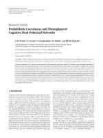
Figure 3: Ergodic achievable rate in [bps/Hz] of a Gaussian multi-
ple relay channel with transmit SNR
= 5 dB, under Rayleigh fading.
The upper and lower bounds proposed in the paper are shown, and
the ergodic capacity of a direct link plotted as reference.
5. ASYMPTOTIC ACHIEVABLE RATE
In previous sections, we analyzed the instantaneous and er-
godic achievable rate of multiple-relay channels with full CSI,
assuming a finite number of potential relays N. Results sug-
gest (as it can be shown in Figure 3) a growth of the spectral
efficiency with the total number relays. Nevertheless, neither
the result in Proposition 2 nor the bounds (25)and(32)are
tractable enough to infer the asymptotic behavior. In this sec-
tion, we introduce the necessary approximations to simplify
the problem and to analyze the asymptotic achievable rate of
the MRC. We show that capacity grows with the logarithm
of the branch zero of the Lambert W function of the total
number of parallel relays.
Prior to the analysis, in the asymptotic domain (N
→∞),
we rename variable n in maximization (9)asn
= κ·N with
κ
∈ [0, 1] (see [25, page 71]), and we introduce four key ap-
proximations.
(1) For a large number of network nodes, we consider ca-
pacities C
n
in (18) defined only by the second slot mu-
tual information,
5
that is,
C
κ·N
=
1
2
C
γ
1κ·N
λ
1
+
1
2
C
γ
2κ·N
λ
2κ·N
≈
1
2
C
γ
2κ·N
λ
2κ·N
.
(33)
5
The proposed approximation is also a lower bound. Thus, the asymptotic
performance of the lower bound is valid to lower bound the asymptotic
performance of the achievable rate.
The proposed approximation is justified by the large
beamforming gain obtained during time slot 2 when
the number of relays grows to
∞ (as shown in ap-
proximation 2). As a consequence, γ
c
κ
·N
computed in
Appendix A is recalculated as
γ
c
κ
·N
= 2P
λ
2κ·N
|b
κ·N
|
2
+ λ
2κ·N
. (34)
To d e r i v e ( 34), we recall that γ
c
κ
·N
is defined in (A.5)
as the power allocation during slot 1 that simulta-
neously satisfies
2
i
=1
γ
i
= 2P and C(γ
1
|b
κ·N
|
2
) =
C(γ
1
λ
1
)+C(γ
2
λ
2κ·N
)(i.e.,γ
c
κ
·N
={γ
1
: C(γ
1
|b
κ·N
|
2
) =
C(γ
1
λ
1
)+C((2P − γ
1
)λ
2κ·N
)}). Hence, neglecting the
factor C(γ
1
λ
1
), then (34) is obtained.
(2) From the Law of Large Numbers, λ
2κ·N
in (10)isap-
proximated as λ
2κ·N
≈ κ·N.
(3) From [25, pages 255–258], the pdf of the or-
dered random variable
|b
κ·N
|
2
asymptotically satis-
fies pdf
|b
κ·N
|
2
= N (Q(1 − κ), ε·N
−1
)asN→∞ (with
ε a fixed constant). Q(κ):[0,1]
→R
+
is the inverse
function of the cdf of the squared modulus of the
nonordered source-to-relay channel defined in (1),
that is , Q(Pr
{|b|
2
<
b}) =
b with b∼CN (0, (d
o
/d)
α
)
and d the source-to-relay random distance. From the
asymptotic pdf, the following convergence in probabil-
ity holds:
b
κ·N
2
P
−→ Q(1 −κ). (35)
(4) We consider high-transmitted power, so that μ
κ·N
≈
P
−1
is in the power allocation (11).
Making use of those four approximations, we may apply (9)
to define the asymptotic instantaneous capacity as
C
a
D&F
=
1
2
lim
N→∞
max
κ∈[0,1]
C
κ·N
≈
1
2
lim
N→∞
max
κ∈[0,1]
C
γ
2κ·N
λ
2κ·N
=
1
2
lim
N→∞
max
κ∈[0,1]
min
C
1
μ
κ·N
−
1
κ·N
κ·N
,
C
2P − γ
c
κ
·N
κ·N
=
1
2
lim
N→∞
max
κ∈[0,1]
min
C(P·κ·N −1),
C
2P
Q(1
−κ)κ·N
Q(1 −κ)+κ·N
,
(36)
where first equality follows from Proposition 2, and second
equality from approximation 1; third equality comes from
the power allocation γ
2κ·N
in (11) and considering λ
2κ·N
=
2κ·N as approximation 2. Finally, forth equality is obtained
making use of approximation 4, and introducing the asymp-
totic convergence of
|b
κ·N
|
2
in (34).
Let us focus now on the last equality in (36). We notice
that (i) C(P
·κ·N −1) is an increasing function in κ ∈ [0, 1],
8 EURASIP Journal on Wireless Communications and Networking
(ii) Q(1−κ) is a decreasing function in the same interval, (iii)
therefore, C(2P(Q(1
− κ)κ·N)/(Q(1 −κ)+κ·N)) is asymp-
totically a decreasing function in κ
∈ [0, 1]. Hence, in the
limit, the maximum in κ of the minimum of an increasing
and a decreasing functions would be given at the intersection
of the two curves. As derived in Appendix C, the intersection
point
6
κ
o
(N)satisfies
κ
o
(N) ≥
W
0
(ρN)
ρN
(37)
with ρ a fixed constant in (0, 1), and with equality when-
ever the relay positions are not random but deterministic. As
mentioned earlier, W
0
(N) is the branch zero of the Lambert
W function evaluated at N [23].
Finally, applying the forth equality in (36), we derive
C
a
D&F
=
1
2
lim
N→∞
C
P·κ
o
(N)·N −1
≥
1
2
lim
N→∞
log
2
P·
W
0
(ρN)
ρ
.
(38)
This result shows that, for any random distribution of relays,
the capacity of MRC with channel knowledge grows asymp-
totically with the logarithm of the Lambert W function of
the total number relays. However, due to approximations 2
and 3, our proof only demonstrates asymptotic performance
in probability.
6. NUMERICAL RESULTS
In this section, we evaluate the lower and upper bounds de-
scribed in (25)and(32), respectively, and compare them
with the ergodic achievable rate of the link, obtained through
Monte Carlo simulation.
As previously pointed out, we assume i.i.d., unitary
mean, Rayleigh-distributed fading from all transmitter nodes
to destination, while source-to-relay channels are modelled
as a superposition of path loss and unitary mean Rayleigh
fading. Likewise, source and destination are fixed nodes,
while the position of the N relays is i.i.d. throughout a
square, limited at its diagonal by the point-to-point source-
to-destination link. As mentioned earlier, the position of re-
lays is invariant during the two-slot communication but vari-
ant and uncorrelated from one transmission to the other.
To deal with propagation effects, we defined a simplified ex-
ponential indoor propagation model with path loss expo-
nent α
= 4. Finally, we consider normalized distances, defin-
ing distance between source and destination equal to 1, and
source-relay random distance d
i
∈ [0, 1].
Taking into account the considerations above, we focus
the analysis on the number of relay nodes and the transmit-
ted SNR, that is, P/σ
2
o
. Figure 3 depicts the ergodic bounds
computed for transmit SNR equal to 5 dB for an MRC with
the number of relay nodes ranging from 5 to 200. Likewise,
6
For a fixed number of relays N, a fixed intersection point κ
o
is derived.
Thus, κ
o
= κ
o
(N).
10
0
10
1
10
2
10
3
Number of relays
2.5
3
3.5
4
4.5
5
5.5
6
(bps/Hz)
Ergodic upper bound, SNR = 10 dB
Ergodic achievable rate
Ergodic lower bound, SNR
= 10 dB
Direct link ergodic capacity, SNR
= 10 dB
Direct link ergodic capacity, SNR
= 15 dB
Direct link ergodic capacity, SNR
= 20 dB
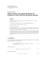
Figure 4: Ergodic achievable rate in [bps/Hz] of a Gaussian multi-
ple relay channel with transmit SNR
= 10 dB, under Rayleigh fad-
ing. The upper and lower bounds proposed in the paper are shown,
and the ergodic capacity of a direct link plotted as reference.
Figures 4 and 5 plot results for transmit SNR equal to 10 dB
and 20 dB, respectively. Firstly, we clearly note that, for all
plots, ergodic bounds and simulated result increase with the
number of users, as we have previously demonstrated in the
asymptotic capacity section.
Moreover, the comparison of the three plots shows that
the advantage of relaying diminishes as the transmitted
power increases. In such a way, it can be seen that for trans-
mit SNR
= 5dBonlyN = 20 parallel relay nodes are needed
to double the noncooperative capacity, while for SNR
=
10 dB more than N = 200 nodes would be necessary to ob-
tain twice the spectral efficiency. Furthermore, we may see
that for SNR
= 5 dB with only 10 relays, it is possible to ob-
tain the same ergodic capacity as a Rayleigh-faded direct link
with SNR
= 10 dB, while to obtain the same power saving
for MRC with SNR
= 20 dB, 50 nodes are needed. Finally,
plots show that the accuracy of the presented bounds grows
as the transmit SNR diminishes, which may be interpreted in
terms of the meaning of such bounds: for decreasing trans-
mitted power, the effect of instantaneous relay selection and
the effect of Rayleigh fading over the cooperative links lose
significance.
Figures 6–8 show results on the mean number of active
relays versus the total number of relay nodes. Recall that the
optimumnumberofrelaynodesiscalculatedfrommaxi-
mization over n in Proposition 2.Specifically,Figure 6 de-
picts results for SNR
= 5 dB while Figures 7 and 8 show
cooperating nodes for SNR
= 10 dB and SNR = 20 dB.
In all three, the number of active nodes n that maximizes
the lower and upper bounds, (25)and(32), respectively, is
A. del Coso and C. Ibars 9
10
0
10
1
10
2
10
3
Number of relays
5.5
6
6.5
7
7.5
8
8.5
9
9.5
(bps/Hz)
Ergodic upper bound, SNR = 15 dB
Ergodic achievable rate
Ergodic lower bound, SNR
= 15 dB
Direct link ergodic capacity, SNR
= 15 dB
Direct link ergodic capacity, SNR
= 20 dB
Direct link ergodic capacity, SNR
= 25 dB
Figure 5: Ergodic achievable rate in [bps/Hz] of a Gaussian multi-
ple relay channel with transmit SNR
= 15 dB, under Rayleigh fad-
ing. The upper and lower bounds proposed in the paper are shown,
and the ergodic capacity of a direct link plotted as reference.
also plotted; hence, it allows for comparison between the
mean number of relays with capacity achieving relaying and
the optimum number of relays with no instantaneous re-
lay selection (25) and with no fading channels (32), respec-
tively. Firstly, results show that the simulated mean num-
ber of relays is close to the number of relays maximizing
the upper and lower bounds, being closer for the low SNR
regime. Finally, we notice that, as the transmit SNR in-
creases, the percentage of relays cooperating with the source
decreases. Therefore, we conclude that regenerative relaying
is, as previously mentioned, more powerful in the low SNR
regime.
7. CONCLUSIONS
In this paper, we examined the achievable rate of a decode-
and-forward (D&F) multiple-relay channel with half-duplex
constraint and transmitter and receiver channel state infor-
mation. The transmission was arranged in two phases: dur-
ing the first phase, the source transmits its message to re-
lays and destination. During the second phase, the relays
and the source are configured as a distributed antenna ar-
ray to transmit extra parity bits. The instantaneous achiev-
able rate for the optimum relay selection and power allo-
cation was obtained. Furthermore, we studied and bounded
the ergodic performance of the achievable rate for Rayleigh-
faded channels. We also found the asymptotic performance
of the achievable rate in number of relays. Results show that
0 20 40 60 80 100 120 140 160 180 200
To t a l nu m b e r o f r e l a y s
10
15
20
25
30
35
40
45
50
55
60
Percentage of active relays (%)
Active relays with the upper bound, SNR = 5dB
Active relays, SNR
= 5dB
Active relays with the lower bound, SNR
= 5dB
Figure 6: Expected number of active relays (in %) of a multiple
relay channel with transmit SNR
= 5 dB, under Rayleigh fading.
The number of relays that optimizes the upper and lower bounds
are shown for comparison.
0 20 40 60 80 100 120 140 160 180 200
To t a l nu m b e r o f r e l a y s
10
15
20
25
30
35
40
45
Percentage of active relays (%)
Active relays with the upper bound
Active relays
Active relays with the lower bound
Figure 7: Expected number of active relays (in %) of a multiple
relay channel with transmit SNR
= 10 dB, under Rayleigh fading.
The number of relays that optimizes the upper and lower bounds
are shown for comparison.
(i) C
D&F
∝ log (W
0
(N)) as N→∞; (ii) with regenerative re-
laying, higher capacity is obtained for low signal-to-noise ra-
tio, (iii) the percentage of active relays (i.e., the number of
nodes who can decode the source message) decreases for in-
creasing N, and (iv) this percentage is low, even at low SNR,
due to the regenerative constraint.
10 EURASIP Journal on Wireless Communications and Networking
0 20 40 60 80 100 120 140 160 180 200
To t a l nu m b e r o f r e l a y s
4
6
8
10
12
14
16
18
20
22
24
Percentage of active relays (%)
Active relays with the upper bound, SNR = 15 dB
Active relays, SNR
= 15 dB
Active relays with the lower bound, SNR
= 15 dB
Figure 8: Expected number of active relays (in %) of a multiple
relay channel with transmit SNR
= 15 dB, under Rayleigh fading.
The number of relays that optimizes the upper and lower bounds
are shown for comparison.
APPENDICES
A. OPTIMIZATION PROBLEM
For completeness of explanation, in the appendix we solve
optimization problem (16), which can be recast as fol-
lows:
C
= max
γ
1
,γ
2
1
2
2
i=1
log
2
1+γ
i
λ
i
s.t.
2
i=1
γ
i
= 2P,
γ
i
≥
Π
2
i
=1
1+γ
i
λ
i
−1
b
n
2
,
(A.1)
whichisconvexinbothγ
1
∈ R
+
and γ
2
∈ R
+
.TheLagrange
dual function of the problem is
L
γ
1
, γ
2
, μ, ν
=
2
i=1
log
1+γ
i
λ
i
−
μ
2
i=1
γ
i
−2P
+ ν
γ
1
−
Π
2
i
=1
(1 + γ
i
λ
i
) −1
|b
n
|
2
,
(A.2)
where μ and ν are the Lagrange multipliers for first and
second constraints, respectively. The three KKT conditions
(necessary and sufficient for optimality) of the dual problem
are
(i)
λ
i
1+γ
i
λ
i
−μ + ν
d
dγ
i
γ
i
−
Π
2
i=1
1+γ
i
λ
i
−
1
b
n
2
=
0
for i
∈{1, 2},
(ii) μ
2
i=1
γ
i
−2P
=
0,
(iii) ν
γ
1
−
Π
2
i
=1
(1 + γ
i
λ
i
) −1
b
n
2
=
0.
(A.3)
Notice that the set (ν
∗
, γ
∗
1
, γ
∗
2
, μ
∗
):
ν
∗
= 0, γ
∗
i
=
1
μ
∗
−
1
λ
i
+
,
1
μ
∗
= P +
1
2
2
i=1
1
λ
i
,
(A.4)
satisfies KKT conditions hence yielding the optimum so-
lution.
7
However, taking into account that optimal primal
points must satisfy the two constraints in (A.1), and that
2
i=1
γ
i
= 2P
γ
1
≥
Π
2
i=1
1+γ
i
λ
i
−1
b
n
2
⎫
⎪
⎪
⎪
⎪
⎪
⎪
⎬
⎪
⎪
⎪
⎪
⎪
⎪
⎭
−→
γ
1
≥γ
c
=φ+
φ
2
+
2P
λ
1
∈ R
+
(A.5)
with φ
= (1/μ
∗
− 1/λ
i
) −|b
n
|
2
/2λ
1
λ
2
. Then, the result in
optimum power allocation is
γ
∗
1
= max
1
μ
∗
−
1
λ
i
, γ
c
,
γ
∗
2
= 2P − γ
∗
1
,
1
μ
∗
= P +
1
2
2
i=1
1
λ
i
.
(A.6)
B. CONCA VITY OF C
N
In the appendix, we prove the concavity of capacity C
n
(de-
fined in (18)basedon(9)) over random variables
|a|
2
,
n
i
=1
|c
i
|
2
,and|b
n
|
2
. To do so, we first rewrite the function
under study as a composition of functions:
C
n
= C
max
Γ
1
(x), Γ
2
(x)
+ C
min
Ψ
1
(x), Ψ
2
(x)
,
(B.7)
7
Using standard notation, we define (A)
+
= max {A,0}.
A. del Coso and C. Ibars 11
where x = [|a|
2
,
n
i
=1
|c
i
|
2
, |b
n
|
2
]and
Γ
1
(x) =
1
μ
n
−
1
|a|
2
|
a|
2
, Γ
1
: R
3+
−→ R,
Γ
2
(x) = γ
c
n
(x)|a|
2
, Γ
2
: R
3+
−→ R,
Ψ
1
(x) =
1
μ
n
−
1
|a|
2
+
n
i
=1
c
i
2
×
|
a|
2
+
n
i=1
c
i
2
, Ψ
1
: R
3+
−→ R,
Ψ
2
(x) =
2P − γ
c
n
(x)
|
a|
2
+
n
i=1
c
i
2
, Ψ
2
: R
3+
−→ R.
(B.8)
First, we notice that pointwise maximum and pointwise
minimum functions are nondecreasing functions with Hes-
sian equal to zero. Next, computing the Hessian of Γ
1
(x)
and Γ
2
(x) (respect to x), it is shown that both are con-
cave functions. Therefore, from [26, pages 86-87], we derive
that max (Γ
1
(x), Γ
2
(x)) is concave on x. Accordingly, we may
show that Ψ
1
(x)andΨ
2
(x) are also concave functions, and
so is min (Ψ
1
(x), Ψ
2
(x)). Hence, considering that the sum of
concave functions is always concave, and that C(x)isacon-
cave nondecreasing function, we derive that C
n
is concave
on x.
C. INTERSECTION OF CAPACITY CURVES
In this appendix, we analyze the intersection point κ
o
of
curves f
1
(κ) = log
2
(P·κN)andf
2
(κ) = log
2
(1 + 2P(Q(1 −
κ)κ·N)/(Q(1 −κ)+κ·N)) for a given number of relays N.To
do so, we set f
1
(κ
o
) = f
2
(κ
o
)toobtain
8
Q
1 −κ
o
≈
κ
o
·N. (C.9)
From approximation 3 in Section 5, equality above is equiv-
alent to
Pr
|
b|
2
≤ κ
o
·N
=
1 −κ
o
(C.10)
with b
∼CN (0, (d
o
/d)
α
)andd the source-to-relay random
distance. Furthermore, making use of the cdf in (23), we ob-
tain
κ
o
= 1 −Pr
|b|
2
≤ κ
o
·N
=
d
+
0
e
−(x/d
o
)
α
κ
o
·N
f
d
(x)dx.
(C.11)
We can now apply Jensen’s inequality for convex functions,
in order to lower bound the integral as
κ
o
≥ e
−(E{x}/d
o
)
α
κ
o
·N
(C.12)
with E
{x}=
d
+
0
xf
d
(x)dx. Equality is satisfied whenever
the relays position are not random but deterministic, that is,
8
Approximation (C.9) is obtained neglecting the effect of 1 within the log-
arithm in f
2
(κ), assuming sufficiently large transmitted power P.
f
d
(x) = δ(x −d
r
). Next, from [23], we directly solve inequal-
ity (C.12)overκ
o
as
κ
o
(N) ≥
W
0
(ρN)
ρN
(C.13)
with ρ
=−(E{x}/d
o
)
α
a fixed constant in (0, 1), and W
0
(·)
the branch zero of the Lambert W function.
This solution is applicable for every possible random dis-
tribution of relays.
ACKNOWLEDGMENTS
The material of this paper was partially presented at the 39th
Asilomar Conference on Signals, Systems and Computers,
Pacific Grove, Calif, November 2005 and at the IEEE Wireless
Communications and Networking Conference (WCNC), Las
Vegas, Nev, March 2006. This work was partially supported
by the Spanish Ministry of Science and Education grant
TEC2005-08122-C03-02/TCM (ULTRARED) and TEC2006-
10459/TCM (PERSEO), by the European Comission un-
der project IST-2005-27402 (WIP) and by Generalitat de
Catalunya under Grant SGR-2005-00690.
REFERENCES
[1] I. Telatar, “Capacity of multi-antenna Gaussian channels,” Eu-
ropean Transactions on Telecommunications,vol.10,no.6,pp.
585–595, 1999.
[2] S. M. Alamouti, “A simple transmit diversity technique for
wireless communications,” IEEE Journal on Selected Areas in
Communications, vol. 16, no. 8, pp. 1451–1458, 1998.
[3] S. Vishwanath, N. Jindal, and A. Goldsmith, “Duality, achiev-
able rates, and sum-rate capacity of Gaussian MIMO broad-
cast channels,” IEEE Transactions on Information Theory,
vol. 49, no. 10, pp. 2658–2668, 2003.
[4] D.TseandP.Viswanath,Fundamentals of Wireless Communi-
cations, Cambridge University Press, Cambridge, UK, 1st edi-
tion, 2005.
[5] E. Zimmermann, P. Herhold, and G. Fettweis, “On the perfor-
mance of cooperative relaying protocols in wireless networks,”
European Transactions on Telecommunications, vol. 16, no. 1,
pp. 5–16, 2005.
[6] G. Kramer, M. Gastpar, and P. Gupta, “Cooperative strategies
and capacity theorems for relay networks,” IEEE Transactions
on Information Theory, vol. 51, no. 9, pp. 3037–3063, 2005.
[7] D. Chen and J. N. Laneman, “The diversity-multiplexing
tradeoff for the multiaccess relay channel,” in Proceedings of
the 40th Annual Conference on Information Sciences and Sys-
tems, pp. 1324–1328, Princeton, NJ, USA, March 2006.
[8] A. Sendonaris, E. Erkip, and B. Aazhang, “User cooperation
diversity—part I: system description,” IEEE Transactions on
Communications, vol. 51, no. 11, pp. 1927–1938, 2003.
[9] A. Høst-Madsen and J. Zhang, “Capacity bounds and power
allocation for wireless relay channels,” IEEE Transactions on
Information Theory, vol. 51, no. 6, pp. 2020–2040, 2005.
[10] T. Cover and A. El Gamal, “Capacity theorems for the relay
channel,” IEEE Transactions on Information Theory, vol. 25,
no. 5, pp. 572–584, 1979.
[11] J. N. Laneman, “Cooperative diversity in wireless net-
works: algorithms and architectures,” Ph.D. Dissertation, Mas-
sachusetts Institute of Technology, Cambridge, Mass, USA,
2002.
12 EURASIP Journal on Wireless Communications and Networking
[12] J. N. Laneman, D. Tse, and G. W. Wornell, “Cooperative diver-
sity in wireless networks: efficient protocols and outage behav-
ior,” IEEE Transactions on Information Theory, vol. 50, no. 12,
pp. 3062–3080, 2004.
[13] A. F. Dana, M. Sharif, R. Gowaikar, B. Hassibi, and M. Effros,
“Is broadcast plus multiaccess optimal for Gaussian wireless
networks?” in Proceedings of the 37th Asilomar Conference on
Signals, Systems, and Computers, vol. 2, pp. 1748–1752, Pacific
Grove, Calif, USA, November 2003.
[14] R. Nabar, H. B
¨
olcskei, and F. W. Kneub
¨
uhler, “Fading relay
channels: performance limits and space-time signal design,”
IEEE Journal on Selected Areas in Communications, vol. 22,
no. 6, pp. 1099–1109, 2004.
[15] A. del Coso and C. Ibars, “Achievable rate for Gaussian multi-
ple relay channels with linear relaying functions,” in Proceed-
ings of IEEE International Conference on Acoustics, Speech, and
Signal Processing (ICASSP ’07), vol. 3, pp. 505–508, Honolulu,
Hawaii, USA, April 2007.
[16] A. El Gamal, M. Mohseni, and S. Zahedi, “Bounds on capacity
and minimum energy-per-bit for AWGN relay channels,” IEEE
Transactions on Information Theory, vol. 52, no. 4, pp. 1545–
1561, 2006.
[17] A. del Coso and C. Ibars, “Partial decoding for synchronous
and asynchronous Gaussian multiple relay channels,” in Pro-
ceedings of the International Conference on Communications
(ICC ’07), pp. 713–718, Glasgow, Scotland, UK, June 2007.
[18] A. Høst-Madsen, “On the capacity of wireless relaying,” in
Proceedings of the 56th IEEE Vehicular Technology Conference
(VTC ’02), vol. 3, pp. 1333–1337, Vancouver, BC, Canada,
September 2002.
[19] A. El Gamal, “Capacity theorems for relay channels,” in Pro -
ceedings of MSRI Workshop on Mathematics of Relaying and Co-
operation in Communication Networks, Berkeley, Calif, USA,
April 2006.
[20] J. N. Laneman and G. W. Wornell, “Distributed space-time-
coded protocols for exploiting cooperative diversity in wireless
networks,” IEEE Transactions on Information Theory, vol. 49,
no. 10, pp. 2415–2425, 2003.
[21] M. Dohler, Virtual antenna arrays, Ph.D. thesis, King’s College
London, London, UK, 2003.
[22] I. Maric and R. Yates, “Bandwidth and power allocation for
cooperative strategies in Gaussian relay networks,” in Proceed-
ings of the 38th Asilomar Conference on Signals, Systems and
Computers, vol. 2, pp. 1907–1911, Pacific Grove, Calif, USA,
November 2004.
[23] R. M. Corless, G. H. Gonnet, D. E. G. Hare, D. J. Jeffrey, and
D. E. Knuth, “On the Lambert W function,” Advances in Com-
putational Mathematics, vol. 5, no. 4, pp. 329–359, 1996.
[24] T. Cover and J. Thomas, Elements of Information Theory,Wiley
Series in Telecommunications, Wiley-Interscience, New York,
NY, USA, 1991.
[25] H. David, Order Stat istics, John Wiley & Sons, New York, NY,
USA, 2rd edition, 1981.
[26] S. Boyd and L. Vandenberghe, Convex Optimization,Cam-
bridge University Press, Cambridge, UK, 1st edition, 2004.