Báo cáo hóa học: " Research Article Performance of a Two-Level Call Admission Control Scheme for DS-CDMA Wireless Networks" potx
Bạn đang xem bản rút gọn của tài liệu. Xem và tải ngay bản đầy đủ của tài liệu tại đây (899.55 KB, 13 trang )
Hindawi Publishing Corporation
EURASIP Journal on Wireless Communications and Networking
Volume 2007, Article ID 21808, 13 pages
doi:10.1155/2007/21808
Research Article
Performance of a Two-Level Call Admission Control Scheme for
DS-CDMA Wireless Networks
Abraham O. Fapojuwo and Yinggan Huang
Department of Electrical and Computer Engineering, The University of Calgary, 2500 University Drive NW,
Calgary, Alberta, Canada T2N 1N4
Received 8 May 2007; Accepted 23 August 2007
Recommended by Sudip Misra
We propose a two-level call admission control (CAC) scheme for direct sequence code division multiple access (DS-CDMA) wire-
less networks supporting multimedia traffic and evaluate its performance. The first-level admission control assigns higher priority
to real-time calls (also referred to as class 0 calls) in gaining access to the system resources. The second level admits nonreal-time
calls (or class 1 calls) based on the resources remaining after meeting the resource needs for real-time calls. However, to ensure
some minimum level of performance for nonreal-time calls, the scheme reserves some resources for such calls. The proposed two-
level CAC scheme utilizes the delay-tolerant characteristic of non-real-time calls by incorporating a queue to temporarily store
those that cannot be assigned resources at the time of initial access. We analyze and evaluate the call blocking, outage probabil-
ity, throughput, and average queuing delay performance of the proposed two-level CAC scheme using Markov chain theory. The
analytic results are validated by simulation results. The numerical results show that the proposed two-level CAC scheme provides
better performance than the single-level CAC scheme. Based on these results, it is concluded that the proposed two-level CAC
scheme serves as a good solution for supporting multimedia applications in DS-CDMA wireless communication systems.
Copyright © 2007 A. O. Fapojuwo and Y. Huang. This is an open access article distributed under the Creative Commons
Attribution License, which permits unrestricted use, distribution, and reproduction in any medium, provided the original work is
properly cited.
1. INTRODUCTION
Recent years have witnessed a great amount of activity on de-
veloping the next-generation wireless networks that are ex-
pected to provide a wide range of services, such as voice,
data, video, and web traffic at very high data rates. Since
the radio spectrum is a very scarce resource, call admis-
sion control (CAC) is becoming one of the most impor-
tant elements of radio resource management. The direct se-
quence code division multiple access (DS-CDMA) technique
is widely used in the second- and third-generation mobile
communication systems. The problem of CAC in DS-CDMA
multimedia wireless networks is very challenging due to the
different quality of service (QoS) requirements of the traf-
fic classes, traffic asymmetry between uplink and downlink
and, for a given traffic class, different treatments between
handoff and new calls. A signal-to-interference ratio- (SIR-)
based CAC scheme is proposed in [1]. In [2], downlink ad-
mission control based on the output power level from base
stations in a CDMA system is studied. The traffic asymme-
try between uplink and downlink of multimedia communi-
cation is researched in [3, 4]. In [5–9], multilayer medium
access control schemes for wireless multimedia services are
proposed. In [4, 10–13], CAC algorithms for serving multi-
ple traffic classes requiring different QoS and multiple trans-
mission rates are considered. In [14], a CAC scheme under
imperfect power control is studied. Seeking solution to the
CAC problem in wireless networks continues to be of ac-
tive research interest in academia and industry; the works in
[15–18] are examples of recently published works in the lit-
erature. Jeon and Jeong [10]proposedaCACschemebased
on SIR measurements for DS-CDMA cellular systems sup-
porting mobile multimedia services. Under the CAC scheme
studied in [10], a call is admitted only when the SIR require-
ments of both the existing and the new calls are guaranteed.
This CAC scheme takes into account the different QoS re-
quirements of multiple traffic classes, assigns the total avail-
able bandwidth to the uplink and downlink asymmetrically,
and guarantees the priority of handoff call requests over the
new call requests within a service class. However, the CAC
scheme described in [10] only focuses on the admission con-
trol at a single level and does not contain any mechanism
2 EURASIP Journal on Wireless Communications and Networking
that takes advantage of the delay-tolerant characteristic of
nonreal-time calls. The two-level CAC scheme proposed in
this paper is similar to the single-level CAC scheme presented
in [10] by using the SIR as the metric for call admission, as-
signs priority to real-time calls over nonreal-time calls, and
accounts for traffic and resource asymmetry in the uplink
and downlink. Our work differs from that of [10]intwo
respects. First, the two-level CAC scheme proposed in this
paper accounts for the provisioned physical resources (e.g.,
channel elements at the base station) in DS-CDMA wireless
networks and incorporates queuing of nonreal-time calls (to
take advantage of their delay-tolerant characteristic) during
physical resource shortage. Second, in the SIR calculation,
the shadowing effect is taken into account in addition to the
distance-dependent path loss that was only considered in the
analysis presented in [10]. Our work is similar to Singh et al.’s
work [13] by queuing nonreal-time calls, but it differs from
that in [13] by performing CAC analysis for both the uplink
and downlink directions, and considering system-level de-
sign parameters (e.g., different admission control thresholds
for new and handoff real-time and nonreal-time calls, reser-
vation bandwidth for nonreal-time calls, and trafficandre-
source asymmetry in downlink and uplink) that are of prac-
tical interest in actual wireless network deployment and pro-
visioning.
The main contribution of this paper is the proposal of
a two-level call admission control scheme for DS-CDMA
wireless networks and the evaluation of its performance.
The proposed scheme is discussed in the context of two
classes of services: real-time and nonreal-time calls. At the
first level, real-time calls are always given a higher priority
over nonreal-time calls in gaining access to system resources.
In addition, within the real-time service class, the handoff
calls are given higher priority over new calls. At the sec-
ond level, the nonreal-time calls are scheduled to transmit
on a first-come, first-served basis at the beginning of each
CDMA frame (slot) according to the available capacity (i.e.,
residual capacity) obtained after subtracting the real-time re-
source requirements from the total resource available. Fur-
ther, a variable parameter, called reservation capacity, is in-
troduced to guarantee some minimum level of performance
for nonreal-time calls. To make use of delay-tolerant char-
acteristic of nonreal-time traffic, a finite queue is used to
temporarily store the nonreal-time calls that cannot begin at
the time of initiation, due to lack of resources. The proposed
two-level CAC scheme is flexible, allowing the total available
bandwidth in a cell to be distributed unequally in the up-
link and downlink directions to account for traffic asymme-
try.
The remainder of this paper is organized as follows.
Section 2 presents the proposed two-level call admission
control scheme. Section 3 contains performance analysis of
the proposed two-level CAC scheme; the analysis outputs
are the performance metrics of call blocking and outage
probabilities, average throughput for both real-time and
nonreal-time calls, and average waiting time of nonreal-
time calls in the queue. Section 4 presents numerical re-
sults and discussion. Finally, Section 5 concludes the pa-
per.
2. PROPOSED TWO-LEVEL CALL ADMISSION
CONTROL SCHEME
Consider a DS-CDMA cellular system offering multime-
dia services each with different QoS requirements. As it
is well known, performance of CDMA-based cellular sys-
tems is interference-limited. Hence, in this paper, the
SIR is used as the metric for call admission. Specifically,
the received energy-per-bit to interference spectral den-
sity ratio (E
b
/I
0
) for a call must be higher than a de-
sired threshold to achieve and maintain the required ser-
vice quality. To this end, a call request (new or hand-
off) is admitted only when the received E
b
/I
0
for the
call and those of all the other active calls (in progress)
are above the E
b
/I
0
threshold value required for accept-
able communication. Without loss of generality, in this pa-
per, multimedia services are classified into real-time and
nonreal-time categories. Due to their different QoS re-
quirements, the two classes are given two different treat-
ments in call admission control, resulting in the two-
level call admission control (CAC). The proposed two-
level CAC relies on two ideas. First, real-time calls are
given a higher priority over nonreal-time calls in accessing
the system resources (i.e., bandwidth). Second, instead of
blocking a nonreal-time call whose resource request can-
not be met at time of initiation, a finite queue is intro-
duced to temporarily store the nonreal-time call. The pro-
posed two-level CAC scheme is described quantitatively as
follows.
2.1. Level 1 call admission control for admission of
real-time calls
The call admission control is based on the noise rise condi-
tion [5, 19, 20]. Denoting the system bandwidth by W, the
noise rise condition can be expressed as
L
=
N
0
i=1
Γ
0,i
R
0,i
+
N
1
i=1
Γ
1,i
R
1,i
≤ W(1 − η), (1)
where L is the aggregate system load, N
0
and N
1
denote the
number of real-time (referred to as class 0, henceforth) and
nonreal-time (referred to as class 1, henceforth) users sup-
ported, respectively, R
0,i
and R
1,i
are the transmission rates
for the ith class 0 and ith class 1 calls, respectively, Γ
0,i
and
Γ
1,i
are the target energy-per-bit to interference spectral den-
sity ratio for the ith class 0 and ith class 1 calls, respectively, η
is the noise rise coefficient defined as the ratio of the back-
ground noise power spectral density to the total (intracell
+ intercell + background noise) received power density, and
(1
− η) is the loading factor threshold. To guarantee some
minimum performance for class 1 calls, some amount of sys-
tem bandwidth W,denotedbyW
res
,isreservedforclass1
calls. The problem is to determine the number of class 0 calls
that can be supported by the remaining bandwidth. Consider
first the uplink direction and assume that Γ
u
0,i
= Γ
u
0
, R
u
0,i
= R
u
0
for all class 0 calls, and Γ
u
1,i
= Γ
u
1
, R
u
1,i
= R
u
1
for all class 1 calls.
Using (1), we have that N
u
0
, the maximum number of class 0
A. O. Fapojuwo and Y. Huang 3
calls supported in the uplink direction when bandwidth W
u
res
is reserved for class 1 calls, is given by
N
u
0
=
W
u
1 − η
u
−W
u
res
α
u
0
Γ
u
0
R
u
0
,(2)
where W
u
is the total available bandwidth in the uplink and
α
u
0
represents the uplink activity factor of class 0 calls. The
superscript “u” denotes uplink direction and the other no-
tations in (2) are as defined previously. The corresponding
expression for N
d
0
, the maximum number of class 0 calls sup-
ported in the downlink direction, is calculated by
N
d
0
=
w
d
1 − η
d
−
(1 − ρ)w
d
res
α
d
0
Γ
d
0
(1 − ρ)R
d
0
,(3)
where ρ is the average orthogonality factor for the cell due to
multipath and the superscript “d” denotes downlink direc-
tion. The overall number of class 0 calls supported in either
the downlink or the uplink direction is
N
0
= min
N
u
0
, N
d
0
. (4)
The resource (bandwidth) required to support the N
0
real-
time calls is therefore reserved. However, the allocation of
resource to class 0 call requests (i.e., both new and handoff
calls) is based on SIR call admission criteria described as fol-
lows. A class 0 new call request is admitted to the system (i.e.,
allocated resources) if
E
x
0
≥ Γ
x
0
,(5a)
E
x
k,0
≥ Φ
x
k,0
,(5b)
where E
x
0
is the received E
b
/I
0
in the x direction, x ∈
{
uplink, downlink}≡{u,d} for the class 0 new call request,
E
x
k,0
is the received E
b
/I
0
in the x direction for an active class
k call, k
∈{0, 1} given that the class 0 new call request is
admitted, and Φ
x
k,0
is the E
b
/I
0
threshold in the x direction
that an active class k call uses to control the admission of a
class 0 new call request. As done in [10], Φ
x
k,0
= β
n
0
Γ
x
k
,where
β
n
0
(> 1) is the multiplicative factor that controls the admis-
sion of class 0 new call requests. Note that the inequality (5b)
is checked for all class k calls that are in progress when the
class 0 new call request is made. Similarly, a class 0 handoff
call request is admitted to the system if
E
x
0
≥ Γ
x
0
,(6a)
E
x
k,0
≥ Ω
x
k,0
,(6b)
where Ω
x
k,0
is the E
b
/I
0
threshold in the x direction that an ac-
tive class k call uses to control the admission of a class 0 hand-
off call request. Also let Ω
x
k,0
= β
h
0
Γ
x
k
[10], where β
h
0
(> 1) is
the multiplicative factor that controls the admission of class
0handoff call requests. The inequality (6b)ischeckedforall
class k calls that are in progress when the class 0 handoff call
request is made. From the foregoing observation, a class 0
new call (or class 0 handoff call) is admitted if the inequali-
ties (5a)and(5b) (or inequalities (6a)and(6b)) are satisfied.
2.2. Level 2 call admission control for admission of
nonreal-time calls
The resource manager assigns resources to service nonreal-
time calls based on the residual resources after those support-
ing real-time calls have been allocated. Using the noise rise
equation, the number of nonreal-time calls (i.e., class 1 calls)
supported in the uplink and downlink directions is given by
N
u
1
= max
W
u
1 − η
u
−
α
u
0
N
u
0
Γ
u
0
R
u
0
α
u
1
Γ
u
1
R
u
1
,
W
u
res
α
u
1
Γ
u
1
R
u
1
,
N
d
1
= max
W
d
1 − η
d
−α
d
0
N
d
0
Γ
d
0
(1 − ρ)R
d
0
α
d
1
Γ
d
1
(1 − ρ)R
d
1
,
W
d
res
α
d
1
Γ
d
1
(1 − ρ)R
d
1
.
(7)
The overall number of nonreal-time calls supported in either
downlink or uplink direction is
N
1
= min
N
u
1
, N
d
1
. (8)
Equation (8) implies that the remaining resources, after sub-
tracting the resources for supporting the N
0
class 0 calls, can
handle a maximum of N
1
class 1 calls. The allocation of the
remaining resources to the class 1 new and handoff call re-
quests is governed by SIR-based admission criteria. Specifi-
cally, a class 1 new call is admitted if
E
x
1
≥ Γ
x
1
,
E
x
k,1
≥ Φ
x
k,1
,
(9)
where E
x
1
, E
x
k,1
,andΦ
x
k,1
have similar definitions as the terms
in (5a)and(5b), but are now defined with respect to class 1
calls and Φ
x
k,1
= β
n
1
Γ
x
k
, β
n
1
> 1. Similarly, a class 1 handoff call
is admitted if
E
x
1
≥ Γ
x
1
,
E
x
k,1
≥ Ω
x
k,1
,
(10)
where Ω
x
k,1
= β
h
1
Γ
x
k
, β
h
1
> 1. If sufficient physical resources are
available to support the requested data rate for the class 1 call,
the call is made active. However, it is possible for the inequal-
ities (9)fornewcalls(or(10) for handoff calls) to be met, but
the call cannot be made active due to physical resource (e.g.,
channel elements) shortage. Instead of blocking such class 1
calls, we take advantage of their delay-tolerant characteristic
and temporarily store such calls in a queue, to be served at
a later time. Note that the queued class 1 calls, even though
admitted into the system, do not generate interference to the
other active calls since they are not yet allocated resources.
At the beginning of every CDMA frame (slot), an attempt is
made to serve (i.e., allocate physical resources) to the queued
nonreal-time calls, on a first-come, fist-served (FCFS) basis.
If the requested physical resources by the head-of-queue call
4 EURASIP Journal on Wireless Communications and Networking
are now available and the inequalities (9)fornewcall(or(10)
for handoff call) are still met, then the scheduler allocates re-
sources to the head-of-queue call and the call then becomes
active. A queued class 1 call is removed from the queue once
it is allocated resources.
3. PERFORMANCE ANALYSIS
The objective of the analysis is to study the performance of a
two-level call admission control that assigns priority of re-
source access to class 0 calls, reserves bandwidth for class
1 calls and temporarily queue class 1 calls that cannot be
served. For analysis, we consider a multicellular DS-CDMA
system. We assume that all the cells are homogeneous and in
statistical equilibrium. Hence, we perform the analysis with
respect to a test user (located in one arbitrary cell) whose
transmission is affected by both intracell interference from
other users in the same cell as the test user, and intercell in-
terference from the surrounding cells.
3.1. Analysis assumptions
The assumptions made in analysis are listed as follows.
A1. Class 0 and class 1 new calls arrive according to in-
dependent Poisson processes with mean call rate Λ
0
and
Λ
1
pertimeunit,respectively.Totalmeancallarrivalrate
Λ
= Λ
0
+ Λ
1
; the decomposition of Λ into Λ
0
and Λ
1
de-
pends on the assumed call mix in the calculations.
A2. Class 0 and class 1 handoff calls arrive according to
independent Poisson processes with mean call rate λ
0
and λ
1
per time unit, respectively.
A3. Duration of a class 0 (class 1) call is exponentially
distributed with mean 1/μ
0
(1/μ
1
).
A4. Dwell time of a user engaged in a class 0 (class 1) call
in a cell is exponentially distributed with mean 1/υ
0
(1/υ
1
).
A5. Connection time for a class 0 call (or class 1 call) al-
ternates between active and dormant states. The length of
active period for a class 0 (or class 1) call is exponentially
distributed with mean 1/ζ
x
0
(1/ζ
x
1
), x ∈{u, d},whereu and
d denote uplink and downlink, respectively. Similarly, the
length of dormant period for a class 0 (class 1) call is expo-
nentially distributed with mean 1/ω
x
0
(1/ω
x
1
), x ∈{u,d}.
A6. Class 1 calls that cannot be allocated resources at the
resource request instant are temporarily stored in a queue of
size Q
pq
.
A7. Patience time for a class 1 call waiting in the queue
is exponentially distributed with mean 1/μ
pq
. For class 1 ap-
plications such as web page or file download, patience time
is interpreted as the maximum time to download a page or a
file. Note that the concept of patience time, as used in this pa-
per, is not for the purpose of resource allocation, but instead
it serves to prevent too long waiting time for the class 1 calls
that are served. A queued class 1 call that has not been served
when its patience time expires, therefore, reneges from the
queue without receiving service.
A8. The received signal or interference power (in dB
unit) is normally distributed with mean determined by the
distance-dependent path loss model and standard deviation
σ dB.
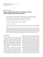
3.2. System model
Based on assumptions A1–A4, A6, and A7, the sys-
tem is modeled by a continuous-time, discrete-state, two-
dimensional Markov chain whose state transition diagram is
shown in Figure 1. Denote the system state by s
= (n
0
, n
tot
),
where n
0
is the number of class 0 calls in a cell and n
tot
is
the total number of class 1 calls in a cell of which n
1
are ac-
tive and n
q
= (n
tot
− n
1
) are waiting in the queue. Denote
the state space of n
0
by S,whereS ={0, 1,2, , N
0
}. Within
the feasible state space S, any state transition is caused by one
of the following events: (1) arrival of a class 0 new call, (2)
arrival of a class 0 handoff call from a neighboring cell, (3)
departure (i.e., handoff)ofanactiveclass0calltoaneigh-
boring cell, and (4) successful completion of a class 0 call.
Similarly, denote the state space of n
tot
by Ψ,whereΨ =
{
0, 1, 2, , N
1
+ Q
pq
}. Recall that n
tot
= n
1
+ n
q
so that the
state space of n
1
and n
q
are, respectively, n
1
∈{0, 1, , N
1
}
and n
q
∈{0, 1, , Q
pq
}. Within the feasible state space Ψ,
any state transition is caused by one of the following events:
(1)arrivalofaclass1newcall,(2)arrivalofaclass1hand-
off call from a neighboring cell, (3) departure (handoff)of
a class 1 call to a neighboring cell, and (4) completion of a
class 1 call. For event 4 causing state transition in Ψ,note
that completion refers to successful or unsuccessful comple-
tion where the latter is due to the departure of a class 1 call
from the queue when its patience time expires (assumption
A7). In Figure 1, the label Y
0
(·, ·) denotes the transition rate
from state n
0
to state (n
0
+1), caused by the arrival of a class 0
(new or handoff) call. Similarly, Y
1
(·, ·) represents the tran-
sition rate from state n
tot
to state (n
tot
+ 1), caused by the
arrivalofaclass1call.AlsoinFigure 1, the label X
0
(·, ·)de-
notes the transition rate from state (n
0
+1) to state n
0
, caused
by the departure of an active class 0 call to a neighboring cell
or successful completion of an active class 0 call. For the ac-
tive class 1 calls, transition from state (n
tot
+ 1) to state n
tot
occurs at rate X
1
(·, ·). The mathematical expressions for the
transition rates are
Y
i
n
0
, n
tot
= q
n
i
n
0
, n
tot
+ q
h
i
n
0
, n
tot
, i ∈{0, 1},
x
i
n
0
, n
tot
=
q
c
i
n
0
, n
tot
+ q
b
i
n
0
, n
tot
, i ∈{0, 1},
(11)
where, for class 0 calls, q
n
0
(n
0
, n
tot
), (q
h
0
(n
0
, n
tot
)) are the
transition rates from state n
0
to state (n
0
+ 1) due to the ar-
rival of a new (handoff) call, and q
b
0
(n
0
, n
tot
), (q
c
0
(n
0
, n
tot
))
are the transition rates from state (n
0
+ 1) to state n
0
caused
by the departure of an active class 0 call to a neighbor-
ing cell (successful completion of an active class 0 call). For
class 1 calls, q
n
1
(n
0
, n
tot
), (q
h
1
(n
0
, n
tot
)) are the transition rates
from state n
tot
to state (n
tot
+ 1) due to the arrival of a new
(handoff) call, and q
b
1
(n
0
, n
tot
), (q
c
1
(n
0
, n
tot
)) are the transi-
tion rates from state (n
tot
+ 1) to state n
tot
caused by the de-
parture of an active class 1 call to a neighboring cell (suc-
cessful completion of an active class 1 call). Note that, for
class 1 calls, X
1
(·, ·) only accounts for successful comple-
tion, and the unsuccessful completion occurs at rate q
r
1
(·, ·)
(see Figure 1). It now remains to determine the expres-
sions for q
n
i
(n
0
, n
tot
), q
h
i
(n
0
, n
tot
), q
b
i
(n
0
, n
tot
), q
c
i
(n
0
, n
tot
), i ∈
{
0, 1},andq
r
1
(n
0
, n
tot
) which are presented in what follows.
A. O. Fapojuwo and Y. Huang 5
Y
1
(0, 0)
X
1
(0, 1)
Y
1
(1, 0)
X
1
(1, 1)
Y
1
(0, 1)
X
1
(0, 2)
Y
1
(1, 1)
X
1
(1, 2)
Y
1
(1, 2)
Y
1
(1, N
1
)
X
1
(1, 3)
X
1
(1, N
1
)
Y
1
(0, 2)
X
1
(0, 3)
Y
1
(0, N
1
)
X
1
(0, N
1
)
Y
1
(0, NQ
1
)
X
1
(0, NQ)+
q
r
1
(NQ)
Y
1
(1, NQ
1
)
X
1
(1, NQ)+
q
r
1
(NQ)
Y
1
(N
0
,0)
X
1
(N
0
,1)
Y
1
(N
0
,0)
X
1
(N
0
,1)
Y
1
(N
0
,1)
X
1
(N
0
,2)
Y
1
(N
0
,1)
X
1
(N
0
,2)
Y
1
(N
0
,2)
X
1
(N
0
,3)
Y
1
(N
0
,2)
X
1
(N
0
,3)
Y
1
(N
0
, NQ
1
)
X
1
(N
0
, NQ)+
q
r
1
(NQ)
Y
1
(N
0
, NQ
1
)
X
1
(N
0
, NQ)+
Y
1
(N
0
, N
1
)
q
r
1
(NQ)
X
1
(N
0
, N
1
)
Y
1
(N
0
, N
1
)
X
1
(N
0
, N
1
)
0, 0 0, 1
1, 11, 0
0, 2
1, 2
0, N
1
1, N
1
0, NQ
1
1, NQ
1
0, NQ
1, NQ
N
0
,0
N
0
,0
N
0
,1
N
0
,1
N
0
,2
N
0
,2
N
0
, N
1
N
0
, N
1
N
0
, NQ
1
N
0
, NQ
1
N
0
, NQ
N
0
, NQ
Y
0
(0, 0)
X
0
(1, 0)
Y
0
(0, 1)
X
0
(1, 1)
Y
0
(0, 2)
X
0
(1, 2)
Y
0
(N
0
,0)
X
0
(N
0
,0)
X
0
(N
0
, NQ)
Y
0
(N
0
, NQ)
Y
0
(N
0
, NQ
1
)
X
0
(N
0
, NQ
1
)
Y
0
(0, NQ
1
)
X
0
(1, NQ
1
)
Y
0
(0, NQ)
X
0
(1, NQ)
Y
0
(N
0
,1)
X
0
(N
0
,1)
Y
0
(N
0
,2)
X
0
(N
0
,2)
···
···
···
···
···
···
···
···
···
.
.
.
.
.
.
.
.
.
.
.
.
.
.
.
.
.
.
Figure 1: Markov state transition diagram for the system (NQ
1
: N
1
+ Q
pq
−1; NQ : N
1
+ Q
pq
; N
0
: N
0
−1).
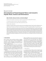
0
0.01
0.02
0.03
0.04
0.05
0.06
0.07
0.08
Class 0 call blocking probability
0.50.55 0.60.65 0.70.75 0.80.85 0.9
Ratio of downlink bandwidth to total bandwidth ( W
d
/W)
New call, 2-level CAC
Handoff call, 2-level CAC
New call, 1-level CAC [10]
Handoff call, 1-level CAC [10]
Figure 2: Class 0 call blocking probabilities versus W
d
/W(Λ =
0.1, W
res
/W =0.1).
3.2.1. Expression for q
n
0
(n
0
, n
tot
)
Let A
n
0
(n
0
, n
tot
) be the probability that the BS, in state
(n
0
, n
tot
), admits a class 0 new call. Using A
n
0
(n
0
, n
tot
)along
with assumption A1 gives the expression for q
n
0
(n
0
, n
tot
)as
q
n
0
n
0
, n
tot
= A
n
0
n
0
, n
tot
Λ
0
, (12)
where A
n
0
(n
0
, n
tot
)isdeterminedasfollows.Recallfrom
Section 2 that a class 0 new call is admitted if the admis-
sion criteria of all the active class k, k
∈{0,1}, calls in both
the uplink and downlink directions (5b) are satisfied. Conse-
quently, we must estimate the mean received E
b
/I
0
for both
uplink and downlink channels of all active calls. Suppose that
when the system is in state s
= (n
0
, n
tot
), there exists an ac-
tivity state φ
s
= (u
0
, d
0
; u
1
, d
1
) that explicitly describes the
actual number of active class 0 and class 1 calls in each of the
uplink (u
0
and u
1
) and downlink (d
0
and d
1
) directions. Let
Q(s) be the state space of all feasible activity states of system
state s,whereQ(s)
={φ
s
:0≤ u
0
, d
0
≤ n
0
;0≤ u
1
, d
1
≤ n
1
}.
Note that 0
≤ u
0
, d
0
≤ n
0
and 0 ≤ u
1
, d
1
≤ n
1
because not
all the n
0
and n
1
calls are active at the same time. Note also
that the upper limit for d
1
is n
1
(not n
tot
) because none of
6 EURASIP Journal on Wireless Communications and Networking
the n
q
class1callsinthequeueisactive.DefinePr{φ
s
} as
the probability that the activity state is φ
s
when the system is
in state s. Since the downlink and uplink transmissions are
independent,
Pr
φ
s
=
n
0
u
0
α
u
0
u
0
1−α
u
0
n
0
−u
0
n
0
d
0
α
d
0
d
0
1−α
d
0
n
0
−d
0
∗
n
1
u
1
α
u
1
u
1
1 − α
u
1
n
1
−u
1
n
1
d
1
α
d
1
d
1
1 − α
d
1
n
1
−d
1
,
(13)
where α
u
j
and α
d
j
are the uplink and downlink activity factors
for call class j, j
={0,1}. Theactivityfactorsaredefinedby
α
x
j
= ω
x
j
/(ω
x
j
+ζ
x
j
), x ∈{u, d}. Define Pr{G
n
0
(n
0
, n
1
, Φ
x
k,0
)|φ
s
}
as the conditional probability that an active class k call allows
for the admission of a class 0 new call when the system is in
activity state φ
s
. As such, the notation {G
n
0
(n
0
, n
1
, Φ
x
k,0
)|φ
s
}
denotes the event that E
x
rcv
(φ
s
), the received E
b
/I
0
when the
system is in activity state φ
s
, exceeds Φ
x
k,0
. The analysis in [10]
computes the admission probability using indicator variables
whose values (1 or 0) are based on whether or not E
x
k,0
(φ
s
),
the average received E
b
/I
0
, exceeds the call admission thresh-
old for acceptable communication. In this paper, we compute
the admission probability by modeling E
x
rcv
(φ
s
), the received
E
b
/I
0
when the system is in activity state φ
s
,asarandomvari-
able (which follows from assumption A8), where the varia-
tion in the received signal and interference power is due to
shadowing. The effect of shadowing was not considered in
the analysis presented in [10]. Hence, the conditional call ad-
mission probability is calculated by
Pr
G
n
0
n
0
, n
1
, Φ
x
k,0
)|φ
s
=
1 − Pr
E
x
rcv
φ
s
< Φ
x
k,0
. (14)
From the assumption of log-normal shadowing, E
x
rcv
(φ
s
)(in
dB unit) is a normal random variable with mean E
x
k,0
(φ
s
)and
standard deviation σ(φ
s
), both expressed in dB. Hence,
Pr
E
x
rcv
φ
s
< Φ
x
k,0
=
1
2
1 − erf
E
x
k,0
φ
s
−
Φ
x
k,0
√
2σ
φ
s
,
(15)
where erf(
·) is the error function. By unconditioning (14)on
φ
s
, making use of (15) and considering all possibilities, we
have
A
n
0
n
0
, n
tot
=
φ
s
∈Q(s)
1
k=0
x∈{u,d}
0.5 − 0.5erf
Φ
x
k,0
−E
x
k,0
φ
s
√
2σ
φ
s
Pr
φ
s
,
(16)
where Pr
{φ
s
} is given by (13). Note that in (15)and(16),
E
x
k,0
(φ
s
), the estimated mean E
b
/I
0
value in the x direction,
now depends on the activity state φ
s
and is given by
E
u
k,0
φ
s
=
1
M
u
k
φ
s
+
R
u
0
Γ
u
0
W
u
Γ
u
k
−1
, k = 0, 1,
E
d
k,0
φ
s
=
1
M
d
k
φ
s
+(1− ρ)
R
d
0
Γ
d
0
W
d
Γ
d
k
−1
, k = 0, 1,
(17)
where M
u
k
(φ
s
)andM
d
k
(φ
s
) denote the average E
b
/I
0
when the
system is in activity state φ
s
in the uplink and downlink, re-
spectively, and they are calculated by
M
u
k
φ
s
=
W
u
Γ
u
k
1
j=0
u
j
R
u
j
Γ
u
j
−R
u
k
Γ
u
k
+ ξ
u
1
j=0
n
j
α
u
j
R
u
j
Γ
u
j
, k = 0, 1,
(18)
M
d
k
φ
s
=
(1 − z)W
d
Γ
d
k
(1 − ρ)
1
j=0
d
j
R
d
j
Γ
d
j
−(1 −ρ)(1 −z)R
d
k
Γ
d
k
+ ξ
d
1
j=0
n
j
α
d
j
R
d
j
Γ
d
j
,
k
= 0, 1.
(19)
In (19), z is the proportion of the total BS transmission
power spent on overhead channels, n
j
is the number of class
j callsinprogressinacell,andξ
u
(ξ
d
) is the ratio of average
uplink (downlink) interference from other cells to average
uplink (downlink) interference from own cell.
3.2.2. Expression for q
n
1
(n
0
, n
tot
)
Applying the same approach described above, the expression
for q
n
1
(n
0
, n
tot
)canbewrittenas
q
n
1
n
0
, n
tot
=
A
n
1
n
0
, n
tot
Λ
1
, (20)
where
A
n
1
n
0
, n
tot
=
φ
s
∈Q(s)
1
k=0
x∈{u,d}
0.5 − 0.5erf
Φ
x
k,1
−E
x
k,1
φ
s
√
2σ
φ
s
Pr
φ
s
.
(21)
3.2.3. Expression for q
h
0
(n
0
, n
tot
)
Let A
h
0
(n
0
, n
tot
) be the probability that the BS, in state
(n
0
, n
tot
), admits a class 0 handoff call. Using A
h
0
(n
0
, n
tot
)
along with assumption A2 gives the expression for
q
h
0
(n
0
, n
tot
)as
q
h
0
n
0
, n
tot
=
A
h
0
n
0
, n
tot
λ
0
. (22)
Derivation of the expression for A
h
0
(n
0
, n
tot
) follows the same
approach as for A
n
0
(n
0
, n
tot
), but now using Ω
x
k,0
.Hence,
A
h
0
n
0
, n
tot
=
φ
s
∈Q(s)
1
k=0
x∈{u,d}
0.5 − 0.5erf
Ω
x
k,0
−E
x
k,0
φ
s
√
2σ
φ
s
Pr
φ
s
.
(23)
A. O. Fapojuwo and Y. Huang 7
3.2.4. Expression for q
h
1
(n
0
, n
tot
)
The transition rate q
h
1
(n
0
, n
tot
)isgivenby
q
h
1
n
0
, n
tot
=
A
h
1
n
tot
λ
1
, (24)
where
A
h
1
n
0
, n
tot
=
φ
s
∈Q(s)
1
k=0
x∈{u,d}
0.5 − 0.5erf
Ω
x
k,1
−E
x
k,1
φ
s
√
2σ
φ
s
Pr
φ
s
.
(25)
3.2.5. Expression for q
c
0
(n
0
+1,n
tot
+1)
The parameter q
c
0
(n
0
+1,n
tot
+1) defines system transitioning
from state (n
0
+ 1) to state n
0
when an active class 0 call is
successfully completed. By assumption A3, the holding time
of a class 0 call is exponentially distributed with mean 1/μ
0
.
Hence,
q
c
0
n
0
+1,n
tot
+1
=
n
0
+1
μ
0
. (26)
3.2.6. Expression for q
c
1
(n
0
+1,n
tot
+1)
Similarly as above, q
c
1
(n
0
+1,n
tot
+ 1) describes state tran-
sitioning from state (n
tot
+ 1) to state n
tot
due to successful
completion of an active class 1 call. Using assumption A3,
q
c
1
n
0
+1,n
tot
+1
=
n
1
+1
μ
1
. (27)
Recall that only n
1
of the n
tot
class 1 calls in the system are
active, each completing at rate μ
1
.
3.2.7. Expression for q
b
0
(n
0
+1,n
tot
+1)
When an MS engaged in a class 0 call while the system is in
state (n
0
+1,n
tot
+ 1) moves to a neighboring cell, the call is
handed off to the cell for continuity of conversation. In this
case, the dwell time in the cell of interest is less than the call
duration. By assumption A4, the cell dwell time of a class 0
call is exponentially distributed with mean 1/υ
0
. Hence, the
mobility induced handoff rate for class 0 calls is given by
q
b
0
n
0
+1,n
tot
+1
=
n
0
+1
υ
0
. (28)
3.2.8. Expression for q
b
1
(n
0
+1,n
tot
+1)
Similarly as above, q
c
1
(n
0
+1,n
tot
+ 1) describes state transi-
tioning from state (n
tot
+ 1) to state n
tot
due to handoff of an
active class 1 call to a neighboring cell. Using assumption A4,
q
b
1
n
0
+1,n
tot
+1
=
n
1
+1
υ
1
. (29)
3.2.9. Expression for q
r
1
(n
0
+1,n
tot
+1)
A class 1 call that is temporarily stored in the queue departs
once its patience time expires. By assumption A7, the pa-
tience time of a class 1 call waiting in the queue is exponen-
tially distributed with mean 1/μ
pq
.Hence,
q
r
1
n
0
+1,n
tot
+1
=
n
tot
+1
−N
1
μ
pq
. (30)
3.3. Steady-state equations
Having determined the expressions for the state transition
rates in Figure 1, we now can write the steady-state balance
equations. Let p(n
0
, n
tot
) denote the steady-state probability
that the system is in state (n
0
, n
tot
). Using the rate equality
principle [21], we write the following balance equations for
all the possible values of n
0
∈ S and n
tot
∈ Ψ :
n
0
= 0, n
tot
= 0:
p(0, 0)
Y
0
(0, 0)+Y
1
(0, 0)
=
p(1, 0)X
0
(1, 0)+ p(0, 1)X
1
(0, 1),
n
0
= 0, 1 ≤n
tot
≤ N
1
−1:
p
0, n
tot
Y
0
0, n
tot
+ Y
1
0, n
tot
+ X
1
0, n
tot
=
p
1, n
tot
X
0
1, n
tot
+ p
0, n
tot
+1
X
1
0, n
tot
+1
+ p
0, n
tot
−1
Y
1
0, n
tot
−1
,
n
0
= 0, n
tot
= N
1
:
p
0, N
1
Y
0
0, N
1
+ Y
1
0, N
1
+ X
1
0, N
1
=
p
1, N
1
X
0
1, N
1
+ p
0, N
1
−1
Y
1
0, N
1
−1
+ p
0, N
1
+1
X
1
0, N
1
+ q
r
1
N
1
+1
,
n
0
= 0, N
1
<n
tot
<N
1
+ Q
pq
:
p
0, n
tot
Y
0
0, n
tot
+ Y
1
0, n
tot
+ X
1
0, n
tot
=
p
1, n
tot
X
0
1, n
tot
+ p
0, n
tot
−1
Y
1
0, n
tot
−1
+ p
0, n
tot
+1
X
1
0, N
1
+ q
r
1
n
tot
+1
,
n
0
= 0, n
tot
= N
1
+ Q
pq
:
p
0, N
1
+Q
pq
Y
0
0, N
1
+Q
pq
+X
1
0, N
1
+q
r
1
N
1
+ Q
pq
=
p
1, N
1
+ Q
pq
X
0
1, N
1
+ Q
pq
+ p
0, N
1
+ Q
pq
−1
Y
1
0, N
1
+ Q
pq
−1
,
(31)
1
≤ n
0
≤ N
0
−1, n
tot
= 0:
p
n
0
,0
Y
0
n
0
,0
+ Y
1
n
0
,0
+ X
0
n
0
,0
=
p
n
0
+1,0
X
0
n
0
+1,0
+ p
n
0
−1, 0
Y
0
n
0
−1, 0
+ p
n
0
,1
X
1
n
0
,1
,
1
≤ n
0
≤ N
0
−1, 1 = n
tot
≤ N
1
−1:
p
n
0
, n
tot
Y
0
n
0
, n
tot
+ Y
1
n
0
, n
tot
+ X
0
n
0
, n
tot
+ X
1
n
0
, n
tot
=
p
n
0
+1,n
tot
X
0
n
0
+1,n
tot
+p
n
0
−1, n
tot
Y
0
n
0
−1, n
tot
+p
n
0
, n
tot
+1
X
1
n
0
, n
tot
+1
+p
n
0
, n
tot
−1
Y
1
n
0
, n
tot
−1
,
1
≤ n
0
≤ N
0
−1, n
tot
= N
1
:
p
n
0
, N
1
Y
0
n
0
, N
1
+Y
1
n
0
, N
1
+X
0
n
0
, N
1
+X
1
n
0
, N
1
=
p
n
0
+1,N
1
X
0
n
0
+1,N
1
+p
n
0
−1, N
1
Y
0
n
0
−1, N
1
+ p
n
0
, N
1
−1
Y
1
n
0
, N
1
−1
+ p
n
0
, N
1
+1
X
1
n
0
, N
1
+ q
r
1
N
1
+1
,
1
≤ n
0
≤ N
0
−1, N
1
<n
tot
<N
1
+ Q
pq
:
p
n
0
, n
tot
Y
0
n
0
, n
tot
+ Y
1
n
0
, n
tot
+ X
0
n
0
, n
tot
+ X
1
n
0
, N
1
+ q
r
1
n
tot
8 EURASIP Journal on Wireless Communications and Networking
= p
n
0
+1,n
tot
X
0
n
0
+1,n
tot
+ p
n
0
−1, n
tot
Y
0
n
0
−1, n
tot
+ p
n
0
, n
tot
−1
Y
1
n
0
, n
tot
−1
+ p
n
0
, n
tot
+1
X
1
n
0
, N
1
+ q
r
1
n
tot
+1
,
(32)
n
0
= N
0
, n
tot
= 0:
p
N
0
,0
Y
1
N
0
,0
+ X
0
N
0
,0
=
p
N
0
−1, 0
Y
0
N
0
−1, 0
+ p
N
0
,1
X
1
N
0
,1
,
n
0
= N
0
,1≤ n
tot
≤ N
1
−1:
p
N
0
, n
tot
Y
1
N
0
, n
tot
+ X
0
N
0
, n
tot
+ X
1
N
0
, n
tot
=
p
N
0
−1, n
tot
Y
0
N
0
−1, n
tot
+ p
N
0
, n
tot
+1
X
1
N
0
, n
tot
+1
+ p
N
0
, n
tot
−1
Y
1
N
0
, n
tot
−1
,
n
0
= N
0
, n
tot
= N
1
:
p
N
0
, N
1
Y
1
N
0
, N
1
+ X
0
N
0
, N
1
+ X
1
N
0
, N
1
=
p
N
0
−1, N
1
Y
0
N
0
−1, N
1
+ p
N
0
, N
1
+1
X
1
N
0
, N
1
+ q
r
1
N
1
+1
+ p
N
0
, N
1
−1
Y
1
N
0
, N
1
−1
,
n
0
= N
0
, N
1
<n
tot
<N
1
+ Q
pq
:
p
N
0
,n
tot
Y
1
N
0
,n
tot
+X
0
N
0
,n
tot
+X
1
N
0
,N
1
+q
r
1
n
tot
=
p
N
0
−1, n
tot
Y
0
N
0
−1, n
tot
+ p
N
0
, n
tot
+1
X
1
N
0
, N
1
+ q
r
1
n
tot
+1
+ p
N
0
, n
tot
−1
Y
1
N
0
, n
tot
−1
,
n
0
= N
0
, n
tot
= N
1
+ Q
pq
:
p
N
0
, N
1
+Q
pq
X
0
N
0
, N
1
+Q
pq
+X
1
N
0
, N
1
+q
r
1
N
1
+Q
pq
=
p
N
0
−1, N
1
+ Q
pq
Y
0
N
0
−1, N
1
+ Q
pq
+ p
N
0
, N
1
+ Q
pq
−1
Y
1
N
0
, N
1
+ Q
pq
−1
.
(33)
The balance equations (31)–(33) along with the normaliza-
tion condition
n
0
∈S
n
tot
∈Ψ
p(n
0
, n
tot
) = 1aresolvedto
obtain the steady-state probabilities p(n
0
, n
tot
)foralln
0
∈ S
and n
tot
∈ Ψ. Let π(n
0
)andτ(n
tot
), respectively, denote the
marginal steady-state probabilities for the number of class 0
and class 1 calls in the system; these marginal probabilities
are calculated by
π
n
0
=
n
tot
∈ψ
p
n
0
, n
tot
,
τ
n
tot
=
n
0
∈S
p
n
0
, n
tot
.
(34)
3.4. Performance measures
The performance measures for the proposed two-level call
admission control scheme are presented in this section.
3.4.1. Blocking probability for new calls
The blocking of a class 0 or class 1 new call is due to two
factors: blocking due to insufficient E
b
/I
0
or blocking due to
insufficient channel resources. The expressions for blocking
probability of a new call are given by
P
(0)
nb
=
n
0
∈S
−
[1 − A
n
0
n
0
π
n
0
+ π
N
0
,
P
(1)
nb
=
n
tot
∈Ψ
−
[1 − A
n
1
n
tot
]τ
n
tot
+ τ
N
1
+ Q
pq
,
(35)
where S
−
={0, 1,2, , N
0
−1}, Ψ
−
={0, 1,2, , N
1
+Q
pq
−
1}, and the superscripts 0 and 1 represent class 0 and class 1
calls, respectively.
3.4.2. Blocking probability for Handoff calls
The blocking or forced termination of a class 0 or class 1
handoff call is also due to two factors: blocking due to insuffi-
cient E
b
/I
0
or blocking due to insufficient channel resources.
The expressions for blocking probability of a handoff call are
given by
P
(0)
hb
=
n
0
∈S
−
[1 − A
h
0
n
0
]π
n
0
+ π
N
0
,
P
(1)
hb
=
n
tot
∈Ψ
−
[1 − A
h
1
n
tot
]τ
n
tot
+ τ
N
1
+ Q
pq
.
(36)
3.4.3. Outage probability for class 0 calls
A real-time call is in outage if the received E
b
/I
0
of the call
falls below the required threshold for acceptable communi-
cation. Since the received E
b
/I
0
is measured at both the MS
and BS, both the downlink and uplink must be tested for out-
age. Let θ
x
0
denote the outage probability for real-time calls
in the x direction, where x
∈{u, d}.θ
x
0
is calculated by the
formula
θ
x
0
=
n
0
∈S
π
n
0
φ
s
∈Q(s)
0.5 − 0.5erf
M
x
0
φ
s
−
Γ
x
0
√
2σ
φ
s
Pr
φ
s
.
(37)
3.4.4. Outage probability for class 1 calls
Similarly, the expression for the outage probability for class 1
calls in the x direction (x
∈{u, d})isgivenby
θ
x
1
=
n
tot
∈Ψ
τ
n
n tot
φ
s
∈Q(s)
0.5−0.5erf
M
x
1
φ
s
−
Γ
x
1
√
2σ
φ
s
Pr
φ
s
,
(38)
where the set Ψ
={0, 1, 2, 3, ,N
1
} spans only the possible
number of class 1 calls that can be in progress and does not
include those waiting in the queue.
3.4.5. Throughput for class 0 calls
Throughput is defined as the allocated data rate under the
condition that the received E
b
/I
0
exceeds the required E
b
/I
0
.
A. O. Fapojuwo and Y. Huang 9
Let Z
x
0
denote the throughput for class 0 calls in the x direc-
tion. The expression for Z
x
0
is given by
Z
x
0
=
n
0
∈S
π
n
0
φ
s
∈Q(s)
0.5−0.5erf
Γ
x
0
−M
x
0
φ
s
√
2σ
φ
s
Pr
φ
s
n
0
R
x
0
.
(39)
The total system throughput due to the active class 0 calls, Z
0
,
is the sum of the throughput for the uplink and downlink,
that is, Z
0
= Z
u
0
+ Z
d
0
.
3.4.6. Throughput for class 1 calls
Similarly, let Z
x
1
denote the throughput for class 1 calls in the
x direction. Then,
Z
x
1
=
n
tot
∈Ψ
τ
n
tot
φ
s
∈Q(s)
0.5−0.5erf
Γ
x
1
−M
x
1
φ
s
√
2σ
φ
s
Pr
φ
s
n
tot
R
x
1
.
(40)
The total system throughput due to class 1 calls, Z
1
, is the
sum of the throughput for the uplink and downlink, that is,
Z
1
= Z
u
1
+ Z
d
1
.
3.4.7. Average queuing delay for class 1 calls
Using Little’s law [22], the average waiting time of class 1 calls
in the queue, E[W], is calculated using the formula
E[W]
=
N
1
+Q
pq
n
tot
=N
1
n
tot
−N
1
τ
n
tot
1 − P
(1)
nb
Λ
1
+
1 − P
(1)
hb
λ
1
. (41)
4. PERFORMANCE RESULTS AND DISCUSSION
One goal of the performance results is to compare the perfor-
mance of the proposed two-level CAC scheme with that of a
previously proposed single-level CAC scheme [10]. Another
objective is to conduct sensitivity analysis to study the ef-
fect of downlink bandwidth ratio and bandwidth reservation
ratio parameters on the system performance metrics of call
blocking, outage probability, average throughput achieved
for both class 0 (real-time) and class 1 (nonreal-time) calls,
and average waiting time in the queue of class 1 calls. The
purpose of the sensitivity analysis is to provide guidance in
the selection of system parameter values to achieve optimal
system performance.
4.1. Assumed input parameter values
Values of system parameters which are specific to the pro-
posed two-level CAC scheme are selected as follows: noise
rise coefficient η
= 0.1, standard deviation of log-normal
shadowing σ
= 8 dB, maximum queue size Q
pq
= 20 class
1 calls, and the average patience time for calls stored in the
queue is 100 seconds. Values of the remaining system pa-
rameters are chosen similarly as those used in [10]. For both
class 0 and class 1 calls, the assumed values for data rates,
activity factors, call mix, mean call duration, and mean cell
dwell time are summarized in Tab le 1 . The required nomi-
nal E
b
/I
0
thresholds for quality communication for the two
traffic classes in the uplink and downlink directions are se-
lected as Γ
u
0
= Γ
u
1
= Γ
d
0
= Γ
d
1
= 4 dB. The call admis-
sion control parameters are set as β
h
0
= 1.05, β
n
0
= 1.1, and
β
h
1
= β
n
1
= 1.2. The ratio of other cell interference to own cell
interference in the uplink (ξ
u
) and downlink (ξ
d
) is chosen
as 0.5. The proportion of the total base-station power spent
on overhead channels, z
= 0.3, and the downlink average or-
thogonality factor in a cell, ρ, is set at 0.5. Unless otherwise
stated, nominal values of downlink bandwidth ratio, band-
width reservation ratio, and total new call arrival rate are
chosen as W
d
/W = 0.8, W
res
/W = 0.1, and Λ = 0.1 calls per
second, respectively. Finally, due to the interdependence be-
tween the mean handoff rate (λ
0
and λ
1
) and the state prob-
abilities p(n
0
, n
tot
), values of the mean handoff rates are not
specified explicitly, but instead they are computed iteratively.
4.2. Performance results
Figure 2 presents class 0 new and handoff call blocking prob-
ability. As the value of downlink bandwidth ratio (W
d
/W)
is varied from 0.5 to 0.9, this range is selected to account
for the higher traffic flow in the downlink compared to up-
link. Other parameter values are set to their nominal values,
as stated earlier. Note the very good agreement between the
simulation results (represented by symbols) and the analy-
sis results (depicted by lines) for the proposed 2-level CAC
scheme. It is observed from Figure 2 that the 2-level CAC
scheme exhibits a lower blocking probability than the 1-level
scheme. The lower blocking performance is due to the fact
that class 0 calls are given higher priority in accessing the
bandwidth resources and the balance is used by class 1 calls.
Notice also that, for the 2-level CAC, the downlink band-
width ratio has no effect on the class 0 call blocking prob-
ability when the value of W
d
/W lies in the range of 0.5 to
0.85. Beyond W
d
/W = 0.85, the blocking level increases
sharply. One implication of the observed call blocking behav-
ior for the 2-level CAC is the flexibility in selecting the band-
width ratio to meet a specified downlink traffic level without
a negative impact on class 0 call blocking level. The above
observation and explanation also apply to the call blocking
performance for class 1 calls, which is shown in Figure 3.A
comparison of the call blocking performance of class 0 and
class 1 calls in Figures 2 and 3 shows that, for the 2-level
CAC scheme and values of W
d
/W in the range of [0.5,0.85],
the class 1 call blocking is the same as class 0 call blocking.
However, for the single-level CAC, class 1 call blocking is
much higher than class 0 call blocking. Class 1 call block-
ing is identical to class 0 call blocking for the 2-level CAC
scheme because of the flexibility of queuing class 1 calls that
cannot be assigned resources at initial access request instant.
Queuing of class 1 calls therefore translates to a reduction in
their blocking level caused by resource shortage. The sensitiv-
ity of call blocking level to new call arrival rate is presented
in Figure 4, for both the 1-level and 2-level CAC schemes.
10 EURASIP Journal on Wireless Communications and Networking
0
0.01
0.02
0.03
0.04
0.05
0.06
0.07
0.08
Class 1 call blocking probability
0.50.55 0.60.65 0.70.75 0.80.85 0.9
Ratio of downlink bandwidth to total bandwidth ( W
d
/W)
New and handoff call, 2-level CAC
New call, 1-level CAC [10]
Handoff call, 1-level CAC [10]
Figure 3: Class 1 call blocking probabilities versus W
d
/W(Λ =
0.1, W
res
/W =0.1).
Table 1: Traffic model parameter values [10].
Class 0 call Class 1 call
Link Uplink Downlink Uplink Downlink
Data rate, R
i
16 kbps 16 kbps 64 kbps 384 kbps
Activity factor, α
i
0.5 0.5 0.00285 0.015
Call mix 90% 10%
Mean call duration, 1/μ
i
120 seconds 3000 seconds
Mean cell dwell time, 1/v
i
300 seconds 1200 seconds
Figure 4 is useful for determining the maximum call arrival
rate that can be supported at a desired call blocking perfor-
mance objective. For example, at a grade of service objective
of 1% call blocking, the proposed 2-level CAC scheme can
support maximum call arrival rates of 0.22 and 0.21 calls/sec
for class 0 and class 1 calls, respectively. These maximum
call arrival rates represent 30% and 75% capacity gain over
the corresponding numbers achieved with the 1-level CAC
scheme. Figure 5 shows the effect of increasing the reserva-
tion bandwidth ratio on the call blocking performance for
class 0 and class 1 calls. It is observed from Figure 5 that class
1 call blocking probability is reduced as the reservation band-
width ratio increases. The penalty though is the concomi-
tant increase in the blocking probabilities for class 0 new and
handoff calls. Figure 5 is useful for determining the proper
value of reservation bandwidth ratio that simultaneously sat-
isfies the call blocking performance objectives for class 0 and
class 1 calls.
Figure 6 presents the uplink and downlink outage prob-
abilities of class 0 and class 1 calls at different values of
W
d
/W for both the 1-level and 2-level CAC schemes. For ei-
ther CAC scheme, the downlink outage probability decreases
as W
d
/W increases. An opposite trend is observed for up-
link outage probability. The preceding statements imply that
0
0.005
0.01
0.015
0.02
0.025
0.03
0.035
0.05
0.04
0.045
Call blocking probabilities
0.05 0.10.15 0.20.25
New call arrival rate
Class 0 call, 1-level CAC [10]
Class 1 call, 1-level CAC [10]
Class 0 call, 2-level CAC
Class 1 call, 2-level CAC
Figure 4: Call blocking probabilities versus aggregate new call ar-
rival rate.
0
0.05
0.1
0.15
0.2
0.25
Call blocking probabilities
0.10.15 0.20.25 0.30.35 0.40.45 0.5
Ratio of reservation bandwidth to total bandwidth (W
res
/W)
Class0newcall
Class 0 handoff call
Class 1 call
Figure 5: Call blocking probabilities versus reservation bandwidth
ratio.
higher bandwidth improves the outage probability. This is
so because the received E
b
/I
0
is directly proportional to the
bandwidth so that a larger bandwidth ensures that the re-
ceived E
b
/I
0
is large enough to always exceed the required
threshold, thereby preventing an outage. It is also interest-
ing to find that, at W
d
/W < 0.53, the downlink outage prob-
ability obtained with the 2-level CAC scheme is higher than
the corresponding result for the 1-level CAC scheme. Beyond
W
d
/W of 0.53, the outage performance for the 2-level CAC
is better than the 1-level CAC scheme. Note that the perfor-
mance improvement is not due to the queuing of class 1 calls
because such calls are not actually active and do not generate
A. O. Fapojuwo and Y. Huang 11
0
1
2
3
4
5
6
7
×10
−3
Class 0 call outage probability
0.50.55 0.60.65 0.70.75 0.80.85 0.9
Ratio of downlink bandwidth to total bandwidth (W
d
/W)
Uplink, 2-level CAC
Downlink, 2-level CAC
Uplink, 1-level CAC [10]
Downlink, 1-level CAC [10]
Figure 6: Outage probabilities versus downlink bandwidth ratio,
W
d
/W.
0
1
2
3
4
5
6
7
×10
−3
Class 1 call outage probability
0.50.55 0.60.65 0.70.75 0.80.85 0.9
Ratio of downlink bandwidth to total bandwidth (W
d
/W)
Uplink, 2-level CAC
Downlink, 2-level CAC
Uplink, 1-level CAC [10]
Downlink, 1-level CAC [10]
Figure 7: Outage probabilities versus downlink bandwidth ratio,
W
d
/W.
interference to the other existing calls. The performance im-
provement is therefore explained by the higher priority as-
signed to class 0 calls in gaining access to system resources
prior to class 1 calls. It is also interesting to find that the 2-
level CAC scheme exhibits a higher downlink outage prob-
ability when W
d
/W ≥ 0.84. The preceding observation for
uplink and downlink outage probabilities suggests that the
2-level CAC scheme is very sensitive to low bandwidth (i.e.,
W
u
/W ≤ 0.16 for uplink and W
d
/W ≤ 0.55 for downlink)
0
0.1
0.2
0.3
0.4
0.5
0.6
0.7
0.8
Throughput (Mbps)
0.50.55 0.60.65 0.70.75 0.80.85 0.9
Ratio of downlink bandwidth to total bandwidth (W
d
/W)
Uplink, 1-level CAC [10]
Downlink, 1-level CAC [10]
Uplink, 2-level CAC
Downlink, 2-level CAC
Figure 8: Average throughput versus downlink bandwidth ratio,
W
d
/W.
resulting in poor performance. Figure 7 presents the corre-
sponding outage probability results for class 1 calls. A com-
parison of Figure 6 with Figure 7 shows that while for the 1-
level CAC scheme, class 1 call downlink outage probability
is higher than the corresponding results for class 0 calls, the
reverse is the case for the 2-level CAC scheme. The uplink
outage probabilities for class 0 and class 1 calls are similar
for either CAC scheme. Figures 6 and 7 are useful for deter-
mining the outage performance targets that correspond to a
specified call blocking objective. For example, the downlink
bandwidth ratio for a 1% call blocking objective is found to
be 0.87 from Figures 2 and 3. Using Figures 6 and 7 and as-
suming the 2-level CAC scheme, the downlink and uplink
outage objectives are 0% and 0.7%, respectively, for class 0
calls and 0% and 0.4% for class 1 calls. Clearly, the outage
probabilities are much less than call blocking, as desired.
Figure 8 compares the uplink and downlink through-
put obtained using the proposed 2-level CAC scheme with
that achieved by the 1-level CAC scheme at different val-
ues of downlink bandwidth ratio. Two observations are evi-
dent from Figure 8. First, the downlink throughput achieved
with the 2-level CAC scheme is roughly double that ob-
tained with the 1-level CAC scheme. The improvement is due
to the queuing of class 1 calls in the 2-level CAC scheme.
The 2-level CAC scheme fully makes use of delay-tolerant
characteristic of class 1 calls to balance the trafficflowbe-
tween class 0 and class 1 calls. Hence, the system resources
areusedmoreefficiently as manifested by the improved
throughput levels. The second observation from Figure 9 is
that while the downlink throughput begins to decrease at
W
d
/W of 85% for the 1-level CAC scheme, the degrada-
tion in throughput for the 2-level CAC scheme begins at
about 87% downlink bandwidth ratio demonstrating better
12 EURASIP Journal on Wireless Communications and Networking
0.1
0.15
0.2
0.25
0.3
0.35
0.4
0.45
0.5
0.55
0.6
Throughput (Mbps)
00.10.20.3
0.40.5
Ratio of reservation bandwidth to total bandwidth (W
res
/W)
Class 0 call
Class 1 call
Figure 9: Throughput versus reservation bandwidth ratio, W
res
/W.
robustness for the 2-level CAC scheme. In case of the up-
link throughput level, the 1-level CAC scheme is more ro-
bust than the 2-level CAC scheme whose throughput level
decreases with W
d
/W. Figure 9 presents the sensitivity of
class 0 and class 1 call throughput levels to reservation band-
width ratio. Clearly, the class 1 call throughput increases as
the reservation bandwidth increases but with a reduction in
the class 0 call throughput levels, as expected. Figures 5 and 9
present the tradeoff between increasing the reservation band-
width ratio to meet a minimum performance objective for
class 1 calls and the degradation in the class 0 call block-
ing and throughput performance. It is concluded from Fig-
ures 5 and 9 that reserving more bandwidth for class 1 calls
translates to lower call blocking and higher throughput but
at the expense of higher call blocking and lower throughput
for class 0 calls.
Figure 10 presents the average waiting time of class 1 calls
assuming the 2-level CAC scheme. The results are plotted
against reservation bandwidth ratio and parameterized by
aggregate new call arrival rate, Λ.ForagivenvalueofΛ, the
average waiting time decreases very rapidly as the bandwidth
reservation ratio is increased. As an example, at an aggregate
new call arrival rate of 0.35 calls/sec, the average waiting time
decreases by 66% when the reservation bandwidth ratio is in-
creased from 0.05 to 0.1. Note from Figure 10 that, for a given
Λ, the average waiting time can be reduced to a small value
(i.e., approximately 2 seconds) by an appropriate choice of
reservation bandwidth ratio. It is found that the reservation
bandwidth ratio to make the average waiting time equal to
zero is higher at large values of aggregate new call arrival rate.
Note, however, that the reservation bandwidth ratio cannot
be increased arbitrarily because of its negative impact on the
throughput and blocking level for class 0 calls, as found ear-
lier from Figures 5 and 9. It is also observed that, at a given
value of reservation bandwidth, the average waiting time for
2
6
8
4
10
12
14
16
20
22
18
Average waiting time of class 1 calls (s)
00.05 0.10.15 0.20.5
Ratio of reservation bandwidth to total bandwidth (W
res
/W)
∧=0.3
∧=0.35
∧=0.4
Figure 10: Average waiting time of class 1 calls versus reservation
bandwidth ratio, W
res
/W.
class 1 calls increases with the call arrival rate, as expected.
For example, at a reservation bandwidth ratio of 10%, the
average waiting times of a class 1 call (e.g., file download) are
3 seconds, 2 seconds and 1 second for Λ
= 0.4, 0.35, and 0.3
calls/sec, respectively.
5. CONCLUSION
In this paper, we propose a two-level call admission control
scheme for wireless DS-CDMA networks carrying multime-
dia traffic.Theschemefullyutilizesthetrafficcharacteristics
of wireless multimedia communication; it assigns higher pri-
ority to the real-time traffic class (i.e., class 0 calls) in gaining
access to the system resources and implements queuing of
nonreal-time calls (i.e., class 1 calls) that cannot be allocated
resources at initial request instant. To ensure that nonreal-
time calls are not starved of resources due to the higher pri-
ority given to real-time calls, the scheme also incorporates
some reserved capacity for nonreal-time calls. For each traf-
fic class, the scheme manages the uplink and downlink re-
sources separately. Further, the scheme also manages the re-
sources to new and handoff calls within each traffic class.
Performance of the proposed two-level CAC scheme is an-
alyzed using Markov chain theory to derive system perfor-
mance metrics of call blocking, outage probability, average
throughput, and average waiting time of nonreal-time calls
in the queue. The numerical results obtained from analy-
sis show that the proposed two-level CAC scheme exhibits
a lower call blocking, lower outage probability, and a higher
throughput than the corresponding results obtained using a
single-level call admission control. For example, our results
show that the two-level call admission control can achieve
up to 75% capacity gain over the single-level CAC scheme.
It is found that the average waiting time introduced by the
queuing of nonreal-time calls can be reduced by appropriate
A. O. Fapojuwo and Y. Huang 13
selection of the reservation bandwidth ratio but this value
must be chosen carefully so as not to seriously degrade the
performance of real-time calls. Based on the results, it is con-
cluded that the proposed two-level CAC scheme would serve
as a viable alternative for managing the resources of a DS-
CDMA wireless communication system.
ACKNOWLEDGMENT
This research is supported in part by a grant from Natu-
ral Sciences and Engineering Research Council (NSERC) of
Canada.
REFERENCES
[1] Z.LiuandM.ElZarki,“SIR-basedcalladmissioncontrolfor
DS-CDMA cellular systems,” IEEE Journal on Selected Areas in
Communications, vol. 12, no. 4, pp. 638–644, 1994.
[2] J.LeeandY.Han,“Downlinkadmissioncontrolformultime-
dia services in WCDMA,” in Proceedings of the 13th IEEE In-
ternational Symposium on Personal, Indoor and Mobile Radio
Communications (PIMRC ’02), vol. 5, pp. 2234–2238, Lisbon,
Portugal, September 2002.
[3] W. S. Jeon and D. G. Jeong, “Call admission control for mobile
multimedia communications with traffic asymmetric between
uplink and downlink,” IEEE Transactions on Vehicular Technol-
ogy, vol. 50, no. 1, pp. 59–66, 2001.
[4] M. Casoni, G. Immovilli, and M. L. Merani, “Admission con-
trol in T/CDMA systems supporting voice and data applica-
tions,” IEEE Transactions on Wireless Communications, vol. 1,
no. 3, pp. 540–548, 2002.
[5] C. Comaniciu, N. B. Mandayam, D. Famolari, and P. Agrawal,
“Wireless access to the World Wide Web in an integrated
CDMA system,” IEEE Transactions on Wireless Communica-
tions, vol. 2, no. 3, pp. 472–483, 2003.
[6] P.R.Larijani,R.H.Hafez,andI.Lambadaris,“Twolevelac-
cess control strategy for multimedia CDMA,” in Proceedings of
IEEE International Conference on Communications (ICC ’98),
vol. 1, pp. 487–492, Atlanta, Ga, USA, June 1998.
[7] C. Comaniciu, N. B. Mandayam, D. Famolari, and P. Agrawal,
“QoS guarantees for third generation (3G) CDMA systems via
admission and flow control,” in Proceedings of the 52nd Ve-
hicular Technology Conference (VTC ’00), vol. 1, pp. 249–256,
Boston, Mass, USA, September 2000.
[8] T K. Liu and J. Silvester, “Joint admission/congestion control
for wireless CDMA systems supporting integrated services,”
IEEE Journal on Selected Areas in Communications, vol. 16,
no. 6, pp. 845–857, 1998.
[9] M. Soroushnejad and E. Geraniotis, “Multi-access strategies
for an integrated voice/data CDMA packet radio network,”
IEEE Transactions on Communications, vol. 43, no. 2–4, pp.
934–945, 1995.
[10] W. S. Jeon and D. G. Jeong, “Call admission control for CDMA
mobile communications systems supporting multimedia ser-
vices,” IEEE Transactions on Wireless Communications, vol. 1,
no. 4, pp. 649–659, 2002.
[11] A. Sampath and J. M. Holtzman, “Access control of data in
integratedvoice/dataCDMAsystems:benefitsandtrade-off,”
IEEE Journal on Selected Areas in Communications, vol. 15,
no. 8, pp. 1511–1526, 1987.
[12] D. Ayyagari and A. Ephremides, “Optimal admission control
in cellular DS-CDMA systems with multimedia traffic,” IEEE
Transactions on Wireless Communications,vol.2,no.1,pp.
195–202, 2003.
[13] S. Singh, V. Krishnamurthy, and H. V. Poor, “Integrated
voice/data call admission control for wireless DS-CDMA sys-
tems,” IEEE Transactions on Signal Processing, vol. 50, no. 6, pp.
1483–1495, 2002.
[14] A. Sampath, P. Kumar, and J. M. Holtzman, “Power control
and resource management for a multimedia CDMA wireless
system,” in Proceedings of the 6th IEEE Internat ional Sympo-
sium on Personal, Indoor and Mobile Radio Communications
(PIMRC ’95), vol. 1, pp. 21–25, Toronto, Canada, September
1995.
[15] S. Aissa, J. Kuri, and P. Mermelstein, “Call admission on the
uplink and downlink of a CDMA system based on total re-
ceived and transmitted powers,” IEEE Transactions on Wireless
Communications, vol. 3, no. 6, pp. 2407–2416, 2004.
[16] G. S. Paschos, I. D. Politis, and S. A. Kotsopoulos, “A qual-
ity of service negotiation-based admission control scheme for
WCDMA mobile wireless multiclass services,” IEEE Transac-
tions on Vehicular Technology, vol. 54, no. 5, pp. 1875–1886,
2005.
[17] X.Yang,G.Feng,andD.S.C.Kheong,“Calladmissioncontrol
for multiservice wireless networks with bandwidth asymmetry
between uplink and downlink,” IEEE Transactions on Vehicular
Technology, vol. 55, no. 1, pp. 360–368, 2006.
[18] W. Li and X. Chao, “Call admission control for an adaptive
heterogeneous multimedia mobile network,” IEEE Transac-
tions on Wireless Communications, vol. 6, no. 2, pp. 515–525,
2007.
[19] A. M. Viterbi and A. J. Viterbi, “Erlang capacity of a power
controlled CDMA system,” IEEE Journal on Selected Areas in
Communications, vol. 11, no. 6, pp. 892–900, 1993.
[20]A.Sampath,N.B.Mandayam,andJ.M.Holtzman,“Er-
lang capacity of a power controlled integrated voice and data
CDMA system,” in Proceedings of the 47th IEEE Vehicular Tech-
nology Conference (VTC ’97), vol. 3, pp. 1557–1561, Phoenix,
Ariz, USA, May 1997.
[21] S. M. Ross, Introduction to Probability Models, Academic Press,
London, UK, 1985.
[22] L. Kleinrock, Queueing Systems. Volume 1: Theory,JohnWiley
& Sons, New York, NY, USA, 1975.