Báo cáo hóa học: " Research Article Wireless Mesh Networks to Support Video Surveillance: Architecture, Protocol, and Implementation Issues" potx
Bạn đang xem bản rút gọn của tài liệu. Xem và tải ngay bản đầy đủ của tài liệu tại đây (2.61 MB, 13 trang )
Hindawi Publishing Corporation
EURASIP Journal on Wireless Communications and Networking
Volume 2007, Article ID 31976, 13 pages
doi:10.1155/2007/31976
Research Article
Wireless Mesh Networks to Support Video Surveillance:
Architecture, Protocol, and Implementation Issues
Francesco Licandro and Giovanni Schembra
Dipartimento di Ingegneria Informatica e delle Telecomunicazioni, University of Catania, Viale A. Doria 6, 95125 Catania, Italy
Received 29 June 2006; Revised 21 December 2006; Accepted 30 January 2007
Recommended by Marco Conti
Current video-surveillance systems typically consist of many video sources distributed over a wide area, transmitting live video
streams to a central location for processing and monitoring. The target of this paper is to present an experience of implementation
of a large-scale video-surveillance system based on a wireless mesh network infr astructure, discussing architecture, protocol, and
implementation issues. More specifically, the paper proposes an architecture for a video-surveillance system, and mainly centers its
focus on the routing protocol to be used in the wireless mesh network, evaluating its impact on performance at the receiver side.
A wireless mesh network was chosen to support a video-surveillance application in order to reduce the overall system costs and
increase scalability and performance. The paper analyzes the performance of the network in order to choose design parameters
that will achieve the best trade-off between video encoding quality and the network tr affic generated.
Copyright © 2007 F. Licandro and G. Schembra. This is an open access article distributed under the Creative Commons
Attribution License, which permits unrestricted use, distribution, and reproduction in any medium, provided the original work is
properly cited.
1. INTRODUCTION
Video-surveillance systems are very important in our daily
lives due to the number of applications they make possible.
The reasons for interest in such systems are diverse, ranging
from security demands and military applications to scientific
purposes. Video-surveillance systems are currently undergo-
ing a transition from traditional analog solutions to digi-
tal ones. This paradigm shift has been triggered by techno-
logicaladvancesaswellasincreasedawarenessoftheneed
for heightened security in particular vertical markets such as
government and transportation. Compared with traditional
analog video-surveillance systems, digital video surveillance
offers much greater flexibility in video content processing
and transmission. At the same time, it can also easily im-
plement advanced features such as motion detection, facial
recognition, and object tracking. Many commercial compa-
nies now offer IP-based surveillance solutions. For exam-
ple, Texas Instruments DSPs can b e used to design vari-
ous video-surveillance systems from low-end to high-end
and from a portable implementation to plug-in implemen-
tation. The TMS320C64x DSP provides users with a high-
resolution video-surveillance system over the Internet proto-
col, thanks to its architecture and peripherals such as video
ports and on-chip ethernet media access controller (EMAC)
[1].
Thepaperstartsfromanexperienceofdeploymentofa
prototype of a large-scale distributed video-surveillance sys-
tem that the authors’ research group is realizing as a com-
mon testbed for many research projects. It consists of sixty
video cameras distributed over the campus of the University
of Catania, transmitting live video streams to a central loca-
tion for processing and monitoring.
Deployment and maintenance of large-scale dist ributed
video-surveillance systems are often very expensive, mainly
due to the installation and maintenance of physical wires.
The solution is chosen in order to significantly reduce the
overall system costs, wh ile increasing deployability, scalabil-
ity, and performance is the use of wireless interconnections
[2, 3].
With this in mind, the idea at the basis of this work is to
applymultihopwirelessmeshnetworks(WMN)[4–9] as the
interconnection backbone of a wireless video-surveillance
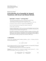
network (WVSN). The proposed architecture is shown in
Figure 1. As we will see in Section 2 , it fits in well with the
structure of a WMN [10], where trafficsourcesarenet-
worked digital video cameras, while the nodes of the WVSN
are fixed and wirelessly interconnected to provide video
2 EURASIP Journal on Wireless Communications and Networking
Internet
WMN
RC-video source
RC-video source
RC-video source
RC-video source
RC-video source
RC-video source
Processing proxy
server (PPS)
Monitoring station
(MS)
Figure 1: WVSN architecture.
sources with connections towards a video proxy with pro-
cessing and filtering capabilities. Video proxies are typically
located in the wired network.
Nevertheless, implementing an intelligent, scalable, and
massively distributed video-surveillance system over wireless
networks remains a research problem and leads to at least the
following important issues, some of which have been raised
by Feng et al. [11]:
(i) transmission bandwidth and transmission power are
scarce resources in wireless environments;
(ii) wireless links are more vulnerable to interceptions and
external attacks;
(iii) the high loss percentage of wireless links requires so-
phisticated techniques for channel encoding that often
increase transmission delays.
On the contrary, a video-surveillance system presents the fol-
lowing features:
(a) commonly used computer vision algorithms in a
video-surveillance environment perform better when
video is encoded with high PSNR and temporal qual-
ity. However, increasing video quality causes an in-
crease in both the required transmission bandwidth
and transmission power;
(b) interceptions and external attacks are a serious prob-
lem in video-surveillance applications;
(c) delay and delay jitter are very harmful, and therefore
must be kept below a given acceptable threshold.
So, the target of this paper is twofold: describing a real ex-
perience based on a new WVSN architecture, defined by the
authors, which is based on a wireless mesh network as the in-
terconnection backbone; analyzing its performance in order
to evaluate some protocol and implementation issues, and
provide some insights into the choice of design parameters
that will optimize the quality of video received at destination
by the processing proxy server. This can be achieved by trying
to obtain the best trade-off between video encoding quality
and the network traffic generated at the source side, and
using suitable routing algorithms in the wireless mesh net-
work. The video quality at destination is evaluated through
an objective quality parameter which is able to simultane-
ously account for packet losses in the network (impacting
the received frame rate) and encoding quality (impacting the
PSNR of the decoded frames).
The paper is structured as follows. Section 2 introduces
the related work. Section 3 describes the proposed architec-
ture. Section 4 discusses the achieved performance. Finally,
Section 5 concludes the paper.
2. RELATED WORK
Analog video-surveillance systems (e.g., CCTV) are in-
creasingly being replaced by more advanced digital video-
surveillance (DVS) solutions, often utilizing IP technologies
and networked architectures. Besides the ever-increasing de-
mand for security, the low cost of cameras and network-
ing devices has contributed to the spread of digital dis-
tributed multimedia surveillance systems. This now consti-
tutes an emerging field that includes signal and image pro-
cessing, computer vision, communications, and hardware.
The automated analysis and processing of video surveil-
lance is a central area of study for the computer vision
and pattern recognition research community. IBM Research’s
PeopleVision [12] project, for example, has focused on the
concept of Smart Surveillance [13], or the application of
automated analysis of surveillance video to reduce the te-
dious, time-consuming task of viewing video feeds from a
large number of security cameras. There have been a num-
ber of famous visual surveillance systems. The real-time vi-
sual surveillance system W4 [14] employs a combination of
shape analysis and tracking and constructs models of peo-
ple’s appearances in order to detect and track groups of peo-
ple as well as monitor their behaviors even in the presence of
occlusion and in outdoor environments. This system uses a
single camera and grayscale sensor. The VIEWS system [15]
F. Licandro and G. Schembra 3
is a 3D-model-based vehicle tracking system. The Pfinder
system [16] is used to recover a 3D description of a person in
a large room. It tracks a single nonoccluded person in com-
plex scenes, a nd has been used in many applications. The sys-
tem at CMU [17] can monitor activities over a large area us-
ing multiple cameras that are connected into a network.
As far as hardware for video surveillance is concerned,
companies like Sony and Intel have designed equipments
suitable for visual surveillance, for example, active cam-
eras, smart cameras [18], omnidirectional cameras [19, 20],
and so on. Networking devices for video surveillance are
the Intelligent Wireless Video Systems proposed by Cisco
with the 3200 Series Wireless and Mobile Routers. Cisco
Systems offer, for example, an outdoor and mobile wire-
less router with intelligent video functions, addressing public
safety and transportation customer needs for highly secure,
cost-efficient, and standards-based video-surveillance appli-
cations [21].
Another important focus of research into video-surveil-
lance systems is on communications between networked
cameras and video processing servers. This is the field of this
paper.
The classical approach to digital video-surveillance sys-
tems is based on wired connections with existing Ether-
net and ATM dedicated-medium networks [22]. Another
wired-based approach is proposed in [23], where IEEE 1394b
FireWire is investigated as a shared medium protocol for ad
hoc, economical installation of video cameras in wireless sen-
sor networks (WSNs). However, they are the cost and perfor-
mance bottleneck to further deployment of large-scale v ideo-
surveillance systems with highly intelligent cameras [11]. A
hybrid routing protocol for future arbitrary topology WSNs
is presented. It uses distributed location servers which main-
tain the route-attribute-location knowledge for routing in
WSNs.
The latest step in the evolution of video-surveillance
systems, aimed at increasing the scalability of large video-
surveillance systems, is the migration to wireless intercon-
nection networks. Many solutions have been proposed in this
context, by both industries and research institutions. Fire-
tide Inc., a developer of wireless multiservice mesh technol-
ogy, and Axis Communications, a company working on net-
work video solutions, have announced a strategic partner-
ship to deliver high-quality video over wireless mesh net-
works, which are being used by a number of cities to provide
wireless video surveillance. In Massachusetts, for example,
the Haverhill Police Department selected these technologies
for its own video-surveillance system [24]. Initially installed
in a small, high-crime area downtown, the solution consists
of Firetide HotPort outdoor and indoor wireless mesh nodes
and AXIS 214 PTZ (pan-tilt-zoom) and AXIS 211 fixed cam-
eras.
A great amount of work has been done to reduce power
consumption in wireless video-surveillance networks. Ref-
erence [25] defines some QoS-parameters in video surveil-
lance, like video data quality and its distortions in net-
work transmission (jitter). Further parameters include qual-
ity metrics such as image size, data rate, or the number of
frames per second (fps). The work in [3] investigates the
trade-off between image quality and power consumption in
wireless video-surveillance networks. However, existing im-
plementations lack comprehensive handling of these three
correlating parameters. In [26], an adaptive checkpointing
algorithm is proposed that also minimizes energy consump-
tion.
Another important issue to be considered from the com-
munications point of view is routing. A very large amount
of research has been carried out regarding routing in ad
hoc wireless networks. Now we have to take into account
that the network environment we are considering in this pa-
per is a wireless mesh network, which is a particular case
of wireless ad hoc networks. In addition, as we will illus-
trate in the following section, we will apply multipath rout-
ing, given that multiple paths can provide load balancing,
fault-tolerance, and higher aggregate bandwidth [27]. Load
balancing can be achieved by spreading the trafficalong
multiple routes. This can alleviate congestion and bottle-
necks. From a fault tolerance p erspective, multipath rout-
ing can provide route resilience. Since bandwidth may be
limited in a wireless network, routing along a single path
may not provide enough bandwidth for a connection. How-
ever, if multiple paths are used simultaneously to route data,
the agg regate bandw idth of the paths can satisfy the band-
width requirement of the application. Also, since there is
more bandwidth available, a smaller end-to-end delay can be
achieved.
Many multipath routing protocols have been defined
in the past literature for ad hoc wireless networks. The
multipath on-demand routing (MOR) protocol [28]wasde-
fined to connect nodes in wireless sensor networks. Other
important routing protocols for ad hoc networks are DSR
[29], TORA [30], and AODV [31]. DSR is an on-demand
routing protocol which works on a source routing basis. Each
transmitted packet is routed carrying the complete route in
its header. TORA is an adaptive on-demand routing protocol
designed to provide multiple loop-free routes to a destina-
tion, thus minimizing reaction to topological changes. The
protocol belongs to the link reversal algorithm family. AODV
is an on-demand distance-vector routing protocol, based on
hop-by-hop routing. It is a modified DSR protocol incorpo-
rating some features presented in the DSDV protocol, such as
the use of hop-by-hop routing, sequence numbers, and peri-
odic beacon messages.
However, all the above protocols are reactive, or on-
demand, meaning that they establish routes as needed. The
advantage of this approach is obvious if only a few routes
are required, since the routing overhead is less than in the
proactive approach of establishing routes whether or not they
are needed. The disadvantage of on-demand establishment
of routes is that connections take more time if the route needs
to be established. However, given that the wireless mesh net-
works considered in this paper have stable topologies because
nodes are fixed and powered, the proactive approach works
better. For this reason we propose to use the distance-vector
multipath network-balancing routing algorithm [32], which
is a proactive routing algorithm.
4 EURASIP Journal on Wireless Communications and Networking
Internet
Processing proxy
server (PPS)
Monitoring station
(MS)
Wireless link
Wired link
Figure 2: WVSN topology.
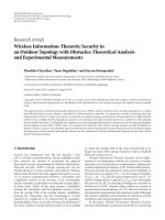
3. DESCRIPTION OF THE WVSN SYSTEM
In this section, we will describe the video-surveillance plat-
form considered in the rest of the paper. The system topol-
ogy is shown in Figure 2.Itismadeofanaccessnetworkand
a core network. In order to monitor six different areas of the
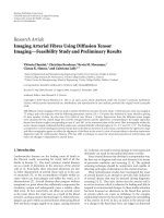
campus, the access network comprises six edge nodes. Edge
and core nodes are sketched in Figure 3.Eachedgenodeis
equipped with one omnidirectional antenna to allow wire-
less access to video cameras. Both edge and core nodes are
routers wirelessly connected to the other nodes by high gain
directional antennas to minimize interferences, and so to
avoid network capacity degradation. All the links of the mesh
network are IEEE 802.11b wireless connections at 11 Mbps.
More specifically, the following antennas have been used:
(a) omnidirectional antenna installed in each edge node
for connection of wireless cameras: pacific wireless
2.4 GHz PAWOD24-12, with a gain of 12 dBi, a fre-
quency range of 2400–2485 MHz, and a vertical beam
width of 7 degrees;
(b) unidirectional antenna installed in each node (both
edge and core) for point-to-point connection with the
other nodes: pacific wireless 2.4 GHz Yagi PAWVA24-
16, with a gain of 16 dBi, a frequency range of 2400–
2485 MHz, and a beam width of 25 degrees.
Radio frequencies have been designed in such a way that
different radio interfaces on the same node use di fferent
radio channels.
The wireless mesh network is connected to the Internet
through the gateway nodes. We have chosen a number of two
gateway nodes to distribute network load and to guarantee
path diversity towards the proxy server.
Video sources are networked digital video cameras con-
nected to the edge nodes through IEEE 802.11b wireless con-
(a) Edge node (b) Core node
Figure 3: Mesh network routers.
nections at 11 Mbps. Specifically, ten wireless video cameras
are connected to each edge node. Video cameras are set to
encode video with a 352
× 288 CIF format, using a stan-
dard MPEG-4 encoder at a bit-rate settable in the range be-
tween 100 kbps and 600 kbit/s, and a frame rate of 12 fps.
Each frame is encoded as an I-frame.
4. WVSN ARCHITECTURE
The distributed architecture defined for the video-
surveillance system is sketched in Figure 1. It consists
of a number of w ireless networked rate-controlled video
cameras (RC-video sources) which, thanks to the WMN,
access the Internet and continuously transmit their video
flows to a processing proxy server (PPS) for processing and
filtering. The PPS is directly, or again through the Internet,
connected to one or more monitoring stations (MS). Not
every video stream that is sent to the PPS for processing is
shown to the end user at the MS. In fact, the PPS analyzes
all the received video flows, and alerts the MS only if a
suspicious event is detected. The focus of our paper is
concentrated on the RC-video sources (and video stream
destination at the PPS) and the wireless mesh network. They
will be described in Sections 4.1 and 4.3. The Processing
Proxy Server will be briefly described in Section 4.2,even
though the internal algorithms are beyond the scope of this
paper.
4.1. RC-video source
The logical architecture of the RC video system is sketched
in Figure 4.Itisanadaptive-rateMPEGvideosourceover
a UDP/IP protocol suite. The video st ream generated by the
video source is encoded by the MPEG encoder according to
F. Licandro and G. Schembra 5
RC-video source
WMN
Rate
controller
MPEG
encoder
IP packetizer
Transmission
buffer
Figure 4: RC-video source architecture.
the MPEG-4 video standard [33, 34]. In the MPEG encoding
standard, each frame, corresponding to a single picture in a
video sequence, is encoded according to one of three possible
encoding modes: intraframes (I), predictive frames (P), and
interpolative frames (B). Typically, I-frames require more
bits than P-frames, while B-frames have the lowest band-
width requirement. For this reason the output rate of MPEG
video sources needs to be controlled, especially if the gener-
ated flow is transmitted on the network. Thus, as usual, a rate
controller combined with the transmission buffer has been
introduced in the video encoding system. It works accord-
ing to a feedback law by appropriately choosing the so-called
quantizer scale parameter (QSP) in such a way that the out-
put rate of the MPEG encoder results in as much constant
as possible. The MPEG encoder output is packetized in the
packetizer according to the UDP/IP protocol suite and sent
to the transmission buffer for transmission.
The QSP value can range within the following set [1, 31]:
1 being the value giving the best encoding quality but requir-
ing the maximum number of bits to encode the frame, and
31 the value giving the worst encoding quality, but requiring
the minimum number of bits. However, let us note that it is
not possible to encode all the frames with the same number
of bits at least for the following three reasons: (1) quantizer
scale is chosen a priori before encoding, and this choice is
only based on long-term video statistics, and not on the par-
ticular frame to be encoded; (2) quantizer scale parameter
can assume 31 values only, and therefore granularity is not
so high to obtain any v alue desired for the number of bits of
the encoded frame; (3) sometimes, for example, when scene
activity is too high or too low, the desired number of bits can-
not be obtained for none of the 31 quantizer scale parame-
ter values. Taking into account this, the transmission buffer
role is necessary to eliminate residual output rate variabil-
ity. In fact, the transmission buffer is served with a constant
rate, and therefore its output is perfectly constant, except for
the cases when it empties. Of course, the transmission bu ffer
queue should not saturate because high delays and losses
should be avoided, and therefore the rate controller presence
is fundamental to maintain the queue around a given thresh-
old, avoiding both empty queue and saturation states.
So the rate controller is necessary to make the output rate
of the MPEG video source constant, avoiding losses in the
transmission buffer, and maximizing encoding quality and
stability. As said so far, it works according to a given feedback
law. This law depends on the activit y of the frame being en-
coded and the current number of packets in the transmission
buffer. More specifically, in order to keep the output rate as
constant as possible, a frame-based feedback law is used [35].
According to this law, the target is to maintain the queue of
the transmission buffer very close to a given threshold, θ
F
.
This is based on the statistics of the video flow, expressed in
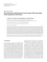
terms of rate and distortion curves [36, 37].
Theratecurves,R
a, j
(q), give the expected number of
bits which will be emitted when the jth frame in the GoP
has to be encoded, if its activity value is a, and is encoded
with a QSP value q. The distortion curves, F
( j)
(q), give the
expected encoding PSNR for each value of the QSP [38].
The rate and distortion curves for the implemented video-
surveillance system are shown in Figure 5.
As said so far, the aim of the rate controller is to maintain
the transmission buffer queue length lower than and very
close to θ
F
at the end of each frame encoding interval. In-
dicating the frame to be encoded as j,itsactivityasa,and
the number of data units in the transmission buffer queue
before encoding as s
Q
, the expected number of packets to en-
code can be calculated from the rate curve, R
a, j
(q). So, the
frame-based feedback law works by choosing the QSP as fol-
lows:
q
= Φ
s
Q
, a, j
=
min
q∈[1,31]
q : s
Q
+ R
a, j
(q) ≤ θ
F
. (1)
4.2. Processing proxy server
The logical architecture of the PPS is sketched in Figure 6.Its
main task is to process the video signals in order to detect an
intrusion in the controlled area and to send the relative video
to the MS.
The RC-video receiver block receives the video flows
from the distributed video-surveillance network through the
Internet. It is made up by three fundamental blocks: a packet
reordering buffer and a jitter compensator buffer, with the aim
of eliminating loss of packet order and delay variations intro-
duced by the network, and an MPEG decoder block to decode
the received video flow.
The decoded video streams are processed by the video
processor and the alarm trigger block. When an intrusion is
6 EURASIP Journal on Wireless Communications and Networking
36
38
40
42
44
46
48
50
52
PSNR (dB)
0 5 10 15 20 25 30 35
Quantizer scale parameter
I-frame
(a) Distortion curve
0
10
20
30
40
50
60
70
80
90
Bit rate (packets/frame)
0 5 10 15 20 25 30 35
Quantizer scale parameter
I-frame
(b) Rate curve
Figure 5: Rate-distortion curves.
Internet
Packet
reordering buffer
Jitter
compensator buffer
MPEG
decoder
RC-video receiver
Packet
reordering buffer
Jitter
compensator buffer
MPEG
decoder
RC-video receiver
Video processor
and alarm trigger
Packet
reordering buffer
Jitter
compensator buffer
MPEG
decoder
RC-video receiver
Video mosaic multiplexer
Monitoring station (MS)
.
.
.
Figure 6: Processing proxy server architecture.
detected by the video processor, the trigger system sends the
relative video images to the video mosaic multiplexer block
which makes a spatial composition of the videos. Finally, the
multiplexer output video is sent to the monitoring station
(MS) for visualization by the final user.
4.3. Wireless mesh network
The WMN constitutes the infrastructure interconnection
network for the wireless video-surveillance system. It com-
prises a number of edge nodes, a number of core nodes, and
F. Licandro and G. Schembra 7
a number of gateway nodes, all interconnected through wire-
less links. It is a multihop wireless network which, unlike
mobile ad hoc networks (MANET), is constituted by fixed
nodes. RC-video sources are connected to edge nodes, while
the WMN is connected to the Internet through the gateway
nodes. The number and location of the edge nodes have to
be chosen in such a way as to allow the connection of all the
networked wireless cameras.
An important role in this architecture is played by the
routing algorithm. Given that the WMN is stable in time
because nodes are powered and fixed, a proactive discovery
of paths is the best solution since it provides reduced packet
delays (deleterious for video-surveillance applications) [39].
On the other hand, additional packet latency due to on-
demand route discovery, typical in reactive routing strategies,
is not acceptable.
Bearing in mind the above-mentioned issues, we have
used a distance-vector multipath network-balancing rout-
ing algorithm [32]. According to this algorithm each node,
thanks to a distance-vector algorithm, knows the distance
from the Internet through each path in the mesh network,
and forwards packets, in a round-robin fashion, through
all the paths having the same minimum cost to reach the
Internet, whatever the destination gateway node is. The
distance-vector multipath network-balancing routing algo-
rithm is used for two reasons: first it is able to reduce delay
[32, 40, 41]; second, thanks to its multipath peculiarity, it in-
creases the robustness of the architecture to external attacks
and interceptions. In fact, if a path is (maliciously or not)
shielded, or its quality is temporally degraded, all the pack-
ets flowing through it are lost; however, the application of
the multipath network-balancing routing algorithm guaran-
tees that a high percentage of packets are able to reach the
video decoder block, and therefore frames can be decoded,
by applying an error concealment video decoding algorithm
[42–44].
Mesh nodes are implemented as software routers run-
ning on low-cost computers with the Click modular router
[45, 46] on a Linux platform. Hardware of each node is re-
alized by using the Soekris Engineer ing net4801 single board
computer, shown in Figure 7(a), chosen as a good trade-off
between costs and performance.
Click is a software architecture for building flexible
and configurable routers. A Click router is assembled from
packet processing modules called elements. Individual ele-
ments implement simple router functions like packet clas-
sification, queueing, scheduling, and interfacing with net-
work devices. A router configuration is a directed graph
with elements at the vertices; packets flow along the edges
of the graph. A standards-compliant Click IP router has
sixteen elements on its forwarding path. Click configura-
tions are modular and easy to extend. The Click modu-
lar router configuration we have designed and implemented
for mesh nodes is shown in Figure 7(b).TheAOMDV
element implements the multipath routing algorithm by
communicating with the other network nodes through
the network interfaces, represented as eth0 and eth1 in
Figure 7(b). Then i t elaborate infor mation and manages the
IP routing table, which is read by the LookupIPRoute ele-
ment.
5. NUMERICAL RESULTS
In this section, we will analyze the performance of the wire-
less v ideo-surveillance system descr ibed so far, and the qual-
ity of service (QoS) perceived at the PPS video processor
block, which is crucial for the detection of suspicious events.
More specifically, we will discuss the following two main
issues:
(i) delay analysis for jitter compensation buffer dimen-
sioning;
(ii) quality of service (QoS) perceived at destination by the
PPS, and in particular by its video processor block,
which is crucial for the detection of suspicious events.
Both analyses are carried out by comparing the distance-
vector multipath network-balancing routing algorithm pro-
posed for this system with classic single-path minimum hop
count routing, in order to evaluate the advantages and disad-
vantages of the proposed approach.
The analysis has been carried out versus the encoding rate
imposed by the rate controller to each video source. This rate
was changed in the range [200, 600] kbps, given that greater
rates cannot be supported by the four bottleneck links con-
necting the mesh network to the gateway nodes, because each
link has a maximum transmission ra te of 11 Mbps.
As regards the delay analysis, we considered both the end-
to-end average delay and the delay jitter, represented by the
standard deviation of the delay distribution [21].
The quality of service (QoS) perceived at destination by
the PPS video processor block depends on both the encoding
quality at the source and losses occurring in the network and
the jitter compensation buffer. More specifically, the encod-
ing quality is decided by setting the quantizer scale parame-
ter, q, as described in Section 4.1. Losses in both the network
and the jitter compensation buffer cause an additional degra-
dation of the quality of the decoded frames at destination,
given that s ome fr a mes will never arrive at destination, while
other fr a mes will arrive corrupted because not all their pack-
ets are available to the decoder at the right time. In this case
an error concealment technique is used at destination to ef-
ficiently reconstruct corrupted and missing frames and thus
improve the quality of the decoded video.
Given that the concealment technique used is beyond
the scope of our paper, in order to achieve results indepen-
dently of it, we assumed that all frames which have registered
a loss percentage greater than a given threshold, here set to
τ
= 20%, are not decodable; instead, frames with fewer lost
packets are reconstructed, with a quality depending on the
percentage of arrived packets.
To summarize, losses in the network and the jitter com-
pensation buffer cause both a reduction in the quality of de-
coded frames, and a frame rate reduction due to nondecod-
able and nonarrived frames.
The quality of decoded frames at destination is described
by the peak signal-to-noise ratio (PSNR), defined as the ratio
8 EURASIP Journal on Wireless Communications and Networking
(a) Soekris Engineering
net4801 board for hardware
implementation
From device (eth0) From device (eth1)
Classifier( )
ARP
queries
ARP
responders
IP AOMDV
Classifier( )
ARP
queries
ARP
responders
IP AOMDV
ARP responder
(1.0.01 )
To A R P q ue r i er
To paint
To q ue u e
Paint (1)
ARP responder
(2.0.0.1 )
To A R P q u e r i e r
To paint
To q ue u e
Paint (2)
From classifier From classifier
Paint (1)
Paint (2)
Strip 14
Chek IP header( )
Get IP address(16)
Look IP route( )
AOMDV( )
To A R P q ue r i er To A RP q ue r i er
To Linux
Drop broadcasts
Check paint(1)
IPGW options(1.0.0.1)
Fix IPSrc(1.0.0.1)
DecIPTTL
IP fragmenter(1500)
From classifier
From AOMDV
ARP querier(1.0.0.1 )
To d e v ic e (e t h0 )
ICM error
redirect
ICM error
bad process
ICM error
TTL expired
ICM error
must frag
Drop broadcasts
Check paint(2)
IPGW options(2.
0.0.1)
Fix IPSrc(2.0.0.1)
DecIPTTL
IP fragmenter(1500)
From classifier
From AOMDV
ARP querier(2.0.0.1 )
To d e v ic e (e t h1 )
ICM error
redirect
ICM error
bad process
ICM error
TTL expired
From device
(eth0)
(b) Click modular router configuration for software implementation
Figure 7: Edge and core node implementation.
between the maximum possible power of a signal and the
power of corrupting noise that affects the fidelity of its rep-
resentation. The PSNR is most easily defined via the mean
squared error (MSE). For two m
× n monochrome images I
and K,whereI is the original image before encoding and K
is the reconstructed image at destination, MSE is defined as
MSE
=
1
m · n
m−1
i=0
n
−1
j=0
I(i, j) − K(i, j)
2
. (2)
Then the PSNR is defined as
PSNR
= 20 log
10
MAX
2
I
MSE
,(3)
where MAX
I
is the maximum pixel value of the image. Since
pixels are represented using 8 bits per sample, this is 255.
More generally, when samples are represented using linear
PCM with B bits per sample, MAX
I
is 2
B
− 1. PSNR is usually
expressed in terms of the logarithmic decibel scale because
manysignalshaveaverywidedynamicrange.
F. Licandro and G. Schembra 9
0.03
0.035
0.04
0.045
0.05
0.055
0.06
0.065
0.07
0.075
Average delay (s)
200 250 300 350 400 450 500 550 600
Bit rate (kbit/s)
Multipath
Single path
Figure 8: End-to-end average delay.
0.5
1
1.5
2
2.5
3
3.5
×10
−3
Delay standard deviation (s)
200 250 300 350 400 450 500 550 600
Bit rate (kbit/s)
Multipath
Single path
Figure 9: End-to-end delay standard deviation.
In order to account for the frame rate reduction as well,
we used the objective quality parameter Q proposed in [22],
defined as
Q
= 0.45 · psnr +
(fr
− 5)
10
− 17.9, (4)
where psnr is the PSNR value measured at the destination,
after error concealment processing, while fr is the frame
rate of the video sequence perceived at destination, counting
decoded frames only. The constant coefficients in (4)were
calculated in [22] by evaluating the data set obtained in a
survey, and assuming a minimum acceptable frame rate of
0
0.05
0.1
0.15
0.2
0.25
0.3
0.35
0.4
0.45
Delay pdf
0.032 0.036 0.04 0.044 0.048
Delay (s)
(a) Source bit rate 200 kbit/s
0
0.02
0.04
0.06
0.08
0.1
0.12
0.14
Delay pdf
0.03 0.04 0.05 0.06 0.07 0.08
Delay (s)
(b) Source bit rate 400 kbit/s
0
0.02
0.04
0.06
0.08
0.1
0.12
0.14
Delay pdf
0.04 0.05 0.06 0.07 0.08 0.09 0.1
Delay (s)
(c) Source bit rate 600 kbit/s
Figure 10: End-to-end delay distribution for single-path routing.
5 frame/s. According to the above definition, the greater the
PSNR and the frame rate at destination are, the greater the Q
parameter is.
Given that the WMN is made up of wireless lossy links,
usually constituting bottlenecks due to their low transmis-
sion capacity, the Internet is considered as lossless, jitter and
losses being introduced by the WMN only.
Figures 8 and 9 show the average value and the measured
standard deviation of the end-to-end delay, respectively. We
can see that multipath routing allows a lower average delay
to be achieved, as compared to single-path routing; however,
it introduces a larger delay jitter, due to the fact that packets
10 EURASIP Journal on Wireless Communications and Networking
0
0.1
0.2
0.3
0.4
0.5
0.6
0.7
0.8
0.9
Delay pdf
0.032 0.036 0.04 0.044
Delay (s)
(a) Multipath 200 kbit/s
0
0.1
0.2
0.3
0.4
0.5
0.6
Delay pdf
0.03 0.04 0.05 0.06
Delay (s)
(b) Multipath 400 kbit/s
0
0.1
0.2
0.3
0.4
0.5
0.6
Delay pdf
0.03 0.04 0.05 0.06
Delay (s)
(c) Multipath 600 kbit/s
Figure 11: End-to-end delay distribution for multipath routing.
25
30
35
40
45
50
55
Average PSNR (dB)
200 250 300 350 400 450 500 550 600
Bit rate (kbit/s)
Multipath
Single path
Figure 12: Average PSNR.
follow different paths, and therefore may experience different
delays. In order to highlight this phenomenon better, Figures
10 and 11 present the end-to-end delay probability distribu-
tions for both the single-path and multipath routing tech-
niques, respectively.
By comparing all the figures from 8 to 11 we can deduce
that multipath routing causes higher jitter values, which have
to be compensated for by the jitter compensator buffer at
the PPS. To this end, delay distributions are used to choose
the value of the threshold σ
J
leaving on its r ight a neglig ible
portion of probability, representing the percentage of packets
that are lost if the jitter compensator buffer equalizes delays
to the chosen threshold σ
J
. Of course, the greater the value
of σ
J
is, the less the loss percentage introduced by the jitter
compensation buffer is, but the higher the equalization delay
is. In our system we chose σ
J
such that 0.1% of packets suffer
a delay g reater than σ
J
, and are therefore discarded.
0
10
20
30
40
50
60
70
Packet loss rate (%)
200 250 300 350 400 450 500 550 600
Bit rate (kbit/s)
Multipath
Single path
Figure 13: Packet loss rate.
In order to evaluate the QoS perceived at destination, we
first calculated the following:
(i) the average PSNR, measured at the destination side as
specified in (2)and(3) on the frames fully or partially
arrived and decoded (Figure 12);
(ii) the packet loss rate in the WMN network (Figure 13);
(iii) the video frame corruption percentage (Figure 14),
and the consequent effective frame r ate, fr,measured
at destination (Figure 15), obtained as the ratio of the
number of frames that have been decoded (also thanks
to the application of the error concealment decoding
technique) over the measurement period.
Figure 12 shows the psnr term, defined in (4) as the PSNR
calculated at the destination, after error concealment pro-
cessing. We can observe that the psnr obtained with multi-
path routing is higher than that obtained with single-path
F. Licandro and G. Schembra 11
0
10
20
30
40
50
60
70
80
90
100
Corrupted frames (%)
200 250 300 350 400 450 500 550 600
Bit rate (kbit/s)
Multipath
Single path
Figure 14: Video frame corruption percentage.
routing. In this case, in fact, the reduced packet loss rate in
the network allows the error concealment algorithm run at
destination to work better, therefore providing frames with
a better quality, more similar to the original ones. How-
ever, when the encoding bit r ate is too high (over 400 kbit/s),
the PSNR increase at the source side corresponds to PSNR
degradation due to network losses, and the PSNR therefore
exhibits a flat trend. Of course, with encoding bit rate val-
ues higher than 600 kbit/s, not shown here because of being
unrealistic due to the enormous loss rate, the curve would
have exhibited a decreasing trend. On the other hand, the
huge number of losses encountered with single-path routing,
which increases with the encoding bit rate, causes a decreas-
ing PSNR trend, although the PSNR at the source increases.
Figures 13 and 14 present the packet loss rate in the
WMN network, and the consequent video frame corrup-
tion percentage. From these figures we can notice that when
the output bit rate increases, the destination frame rate
achieved with single-path routing soon becomes too low,
while multipath routing allows the source to encode at a high
rate while maintaining a high destination frame rate: losses
remain low up to 400 kbps.
As shown in Figure 14, with low bit rate values, we can
reduce packet losses by decreasing the video source trans-
mission bit rate. In fact, by decreasing it, the probability of
a packet being discarded decreases, and the received video
quality grows.
Finally, Figure 16 summarizes the QoS perceived at des-
tination by showing the overall objective quality parameter
Q defined in (4), and demonstrates the power of multipath
routing in guaranteeing a perceived QoS greater than that
achieved by single-path routing with any video source output
rate. The behavior of this parameter is determined by both
the psnr parameter shown in Figure 12, and the fr parameter
shown in Figure 15. We can observe that when single-path
routing is used the overall quality decreases with increasing
0
2
4
6
8
10
12
Average frame rate (%)
200 250 300 350 400 450 500 550 600
Bit rate (kbit/s)
Multipath
Single path
Figure 15: Average video frame rate, fr.
−6
−4
−2
0
2
4
6
Q parameter
200 250 300 350 400 450 500 550 600
Bit rate (kbit/s)
Multipath
Single path
Figure 16: Objective parameter Q.
encoding bit rates, and the best quality is achieved with the
minimum considered encoding bit rate, equal to 200 kbit/s.
On the contrary, using multipath routing allows us to encode
at a higher bit rate the best being between 500 and 600 kbit/s.
To summarize, taking into account that multipath rout-
ing, besides robustness to external attacks and interceptions,
provides a higher decoding quality and less delay than single-
path routing, it is the best solution for the proposed video-
surveillance system. The only problem of multipath routing
is that delay jitter is higher, but this can be compensated for
by a compensation buffer at destination.
12 EURASIP Journal on Wireless Communications and Networking
6. CONCLUSIONS
This paper describes a real experience of a wireless video-
surveillance system, illustrating the overall architecture and
the structure of each component block. Specifically, video
sources use rate control to emit a constant bit-rate flow,
while the access network is a WMN implementing a mul-
tipath routing algorithm to minimize delay and intrusions.
However, this causes jitter, which is not acceptable for video-
surveillance applications but can be compensated at desti-
nation if delay statistics are known. Analysis is carried out
against the emission bit rate, and quality perceived at desti-
nation is evaluated with an objective parameter. Numerical
results have demonstrated that multipath routing guarantees
less delay and the best quality at destination. So it is the best
solution for the proposed video-surveillance system with any
encoding bit rate.
ACKNOWLEDGMENTS
The authors wish to thank the anonymous reviewers for their
detailed reviews and many constructive suggestions which
have improved the paper significantly. The work was par-
tially supported by the Italian Ministry for University and
Scientific Research (MIUR) through the BORA-BORA Prin
project under Grant 2005097340.
REFERENCES
[1] C. Peng, “Introduction to Video-Surveillance Systems over the
Internet Protocol,” Real World Video & Imaging: Texas Instru-
ments White Papers, October 2003.
[2] R. T. Collins, A. J. Lipton, H. Fujiyoshi, and T. Kanade, “Algo-
rithms for cooperative multisensor surveillance,” Proceedings
of the IEEE, vol. 89, no. 10, pp. 1456–1477, 2001.
[3] C F. Chiasserini and E. Magli, “Energy consumption and im-
age quality in wireless v ideo-surveillance networks,” in Pro-
ceedings of the 13th IEEE International Symposium on Personal,
Indoor and Mobile Radio Communications (PIMRC ’02), vol. 5,
pp. 2357–2361, Lisbon, Portugal, September 2002.
[4] I. F. Akyildiz, X. Wang, and W. Wang, “Wireless mesh net-
works: a survey,” Computer Networks, vol. 47, no. 4, pp. 445–
487, 2005.
[5] Mesh Networks, />[6] Radiant Networks, />[7] R. Karrer, A. Sabharwal, and E. Knightly, “Enabling large-
scale wireless broadband: the case for TAPs,” in Proceedings of
the 2nd Workshop on Hot Topics in Networks (HotNets-II ’03),
Cambridge, Mass, USA, November 2004.
[8] P. Bhagwat, B. Raman, and D. Sanghi, “Turning 802.11 inside-
out,” in Proceedings of the 2nd Workshop on Hot Topics in
Networks (HotNets-II ’03), Cambridge, Mass, USA, November
2003.
[9] Tropos Networks, />[10] R. Draves, J. Padhye, and B. Zill, “Routing in multi-radio,
multi-hop wireless mesh networks,” in Proceedings of the 10th
Annual International Conference on Mobile Computing and
Networking (MOBICOM ’04), pp. 114–128, Philadelphia, Pa,
USA, September-October 2004.
[11] W. Feng, J. Walpole, W. Feng, and C. Pu, “Moving towards
massively scalable video-based sensor networks,” in Proceed-
ings of the Workshop on New Visions for Large-Scale Networks:
Research and Applications, pp. 12–14, Washington, DC, USA,
March 2001.
[12] PeopleVision Project, IBM Research, earch.
ibm.com/peoplevision/.
[13] A. Hampapur, L. Brown, J. Connell, S. Pankanti, A. Senior, and
Y. Tian, “Smart surveillance: applications, technologies and
implications,” in Proceedings of the Joint Conference of the 4th
International Conference on Information, Communications and
Signal Processing, and the 4th Pacific Rim Conference on Multi-
media, vol. 2, pp. 1133–1138, Singapore, December 2003.
[14] I. Haritaoglu, D. Harwood, and L. S. Davis, “W
4
: real-time
surveillance of people and their activities,” IEEE Transactions
on Pattern Analysis and Machine Intelligence, vol. 22, no. 8, pp.
809–830, 2000.
[15] T. N. Tan, G. D. Sullivan, and K. D. Baker, “Model-based local-
isation and recognition of road vehicles,” International Journal
of Computer Vision, vol. 27, no. 1, pp. 5–25, 1998.
[16] C. R. Wren, A. Azarbayejani, T. Darrell, and A. P. Pentland,
“Pfinder: real-time tracking of the human body,” IEEE Trans-
actions on Pattern Analysis and Machine Intelligence, vol. 19,
no. 7, pp. 780–785, 1997.
[17] A. J. Lipton, H. Fujiyoshi, and R. S. Patil, “Moving target clas-
sification and tracking from real-time video,” in Proceedings
of the 4th IEEE Workshop on Applications of Computer Vision
(WACV ’98), pp. 8–14, Princeton, NJ, USA, October 1998.
[18] S. E. Kemeny, R. Panicacci, B. Pain, L. Matthies, and E. R.
Fossum, “Multiresolution image sensor,” IEEE Transactions on
Circuits and Systems for Video Technology,vol.7,no.4,pp.
575–583, 1997.
[19] T. Boult, “Frame-rate multi-body tracking for surveillance,”
in Proceedings of DARPA Image Understanding Workshop,pp.
305–308, Monterey, Calif, USA, November 1998.
[20] A. Basu and D. Southwell, “Omni-directional sensors for pipe
inspection,” in Proceedings of the IEEE International Conference
on Systems, Man and Cybernetics, vol. 4, pp. 3107–3112, Van-
couver, BC, Canada, October 1995.
[21] Cisco Systems documentation, “Intelligent Wireless Video
Surveillance S olutions,” />ducts/hw/routers/ps272/prod
brochure0900aecd804a8cad.
html.
[22] “People-Mover Project Brings 21st Century Surveillance
System to Dallas Airport,” Telindus, 2002 http://www.
telindus.com/resources/ref
case dallas-screen.pdf.
[23] V. Chandramohan and K. Christensen, “A first look at wired
sensor networks for video surveillance systems,” in Proceedings
of the 27th Annual IEEE Conference on Local Computer Net-
works (LCN ’02), pp. 728–729, Tampa, Fla, USA, November
2002.
[24] “Firetide, Axis partner to deliver wireless video surveil-
lance,” Telematics Journal, September 2006, http://www.
telematicsjournal.com/content/newsfeed/8344.html.
[25] A. Doblander, A. Maier, and B. Rinner, “Increasing service
availability in intelligent video surveillance systems by fault
detection and dynamic reconfiguration,” in Proceedings of
the Telecommunications and Mobile Computing Workshop on
Wearable and Pervasive Computing (TCMC ’05),Graz,Austria,
March 2005.
[26] Y. Zhang and K. Chakrabarty, “Energy-aware adaptive check-
pointing in embedded real-time systems,” in Proceedings of the
Design, Automation and Test in Europe Conference and Exhibi-
tion (DATE ’03), pp. 918–923, Paris, France, March 2003.
[27] S. Mueller, R. P. Tsang, and D. Ghosal, “Multipath rout-
ing in mobile ad hoc networks: issues and challenges,” in
F. Licandro and G. Schembra 13
Perfor mance Tools and Applications to Networked Syste ms,M.
C. Calzarossa and E. Gelenbe, Eds., vol. 2965 of Lecture Notes
in Computer Science, pp. 209–234, Springer, Berlin, Germany,
2004.
[28] E. Biagioni and S. H. Chen, “A reliability layer for ad-hoc wire-
less sensor network routing,” in Proceedings of the 37th Hawaii
International Conference on System Sciences (HICSS ’04),pp.
4799–4806, Big Island, Hawaii, USA, January 2004.
[29] D. B. Johnson, D. A. Maltz, and J. Broch, “DSR: the dy-
namic source routing protocol for multi-hop wireless ad hoc
networks,” in Ad Hoc Networking, chapter 5, pp. 139–172,
Addison-Wesley, New York, NY, USA, 2001.
[30] V. D. Park and M. S. Corson, “A highly adaptive distributed
routing algorithm for mobile wireless networks,” in Proceed-
ings of the 16th Annual Joint Conference of the IEEE Com-
puter and Communications Societies (INFOCOM ’97), vol. 3,
pp. 1405–1413, Kobe, Japan, April 1997.
[31] C. E. Perkings, E. Belding-Royer, and S. R. Das, “Ad hoc on-
demand distance vector routing,” RFC 3561, 2003.
[32] S. Vutukury and J. J. Garcia-Luna-Aceves, “MDVA: a distance-
vector multipath routing protocol,” in Proceedings of the 20th
Annual Joint Conference on the IEEE Computer and Communi-
cations Societies (INFOCOM ’01), vol. 1, pp. 557–564, Anchor-
age, Alaska, USA, April 2001.
[33] “Coded Representation of Picture and Audio Information,”
International Standard ISOIEC/JTC1/ Sc29/WG11, MPEG
Test Model 2. July 1992.
[34] “Coding of Moving Pictures and Associated Audio for Dig-
ital Storage Media up to 1.5 Mbit/s—Part 2,” Video. Inter-
national Standard ISO-IEC/JTC1/SC29/WG11, DIS11172-1.
March 1992.
[35] A. Lombardo and G. Schembra, “Performance evaluation of
an adaptive-rate MPEG encoder matching intserv trafficcon-
straints,” IEEE/ACM Transactions on Networking,vol.11,no.1,
pp. 47–65, 2003.
[36] C F. Chang and J S. Wang, “A stable buffer control strategy
for MPEG coding,” IEEE Transactions on Circuits and Systems
for Video Technology, vol. 7, no. 6, pp. 920–924, 1997.
[37] A. Cernuto, F. Cocimano, A. Lombardo, and G. Schembra, “A
queueing system model for the design of feedback laws in rate-
controlled MPEG video encoders,” IEEE Transactions on Cir-
cuits and Systems for Video Technology, vol. 12, no. 4, pp. 238–
255, 2002.
[38] W. Ding and B. Liu, “Rate control of MPEG video coding and
recording by rate-quantization modeling,” IEEE Transactions
on Circuits and Systems for Video Technology,vol.6,no.1,pp.
12–20, 1996.
[39] X. Yuan, Z. Sun, Y. Varol, and G. Bebis, “A distributed visual
surveillance system,” in Proceedings of the IEEE Conference on
Advanced Video and Signal Based Surveillance (AVSS ’03),pp.
199–204, Miami, Fla, USA, July 2003.
[40] S. Vutukur y and J. J. Garcia-Luna-Aceves, “A simple ap-
proximation to minimum-delay routing,” in Proceedings of
the ACM Conference on Applications, Technologies, Architec-
tures, and Protocols for Computer Communication (ACM SIG-
COMM ’99), pp. 227–238, Cambridge, Mass, USA, August-
September 1999.
[41] S. Vutukury and J. J. Garcia-Luna-Aceves, “A practical frame-
work for minimum-delay routing in computer networks,”
Journal of High Speed Networks, vol. 8, no. 4, pp. 241–263,
1999.
[42] Y C. Lee, Y. Altunbasak, and R. M. Mersereau, “Multi-
frame error concealment for MPEG-coded video delivery over
error-prone networks,” IEEE Transactions on Image Processing,
vol. 11, no. 11, pp. 1314–1331, 2002.
[43] S C. Pei and Y Z. Chou, “Novel error concealment method
with adaptive prediction to the abrupt and gradual scene
changes,” IEEE Transactions on Multimedia,vol.6,no.1,pp.
158–173, 2004.
[44] S. Tsekeridou and I. Pitas, “MPEG-2 error concealment based
on block-matching principles,” IEEE Transactions on Circuits
and Systems for Video Technology
, vol. 10, no. 4, pp. 646–658,
2000.
[45] “The Click Modular Router Project,” .
edu/click/.
[46] R. Morris, E. Kohler, J. Jannotti, and M. F. Kaashoek, “The
click modular router,” in Proceedings of the 17th ACM Sympo-
sium on Operating System Principles (SOSP ’99), pp. 217–231,
Kiawah Island Resort, SC, USA, December 1999.