Báo cáo hóa học: " Research Article Modelling and Comparative Performance Analysis of a Time-Reversed UWB System" doc
Bạn đang xem bản rút gọn của tài liệu. Xem và tải ngay bản đầy đủ của tài liệu tại đây (1.01 MB, 11 trang )
Hindawi Publishing Corporation
EURASIP Journal on Wireless Communications and Networking
Volume 2007, Article ID 71610, 11 pages
doi:10.1155/2007/71610
Research Article
Modelling and Comparative Performance Analysis of
a Time-Reversed UWB System
K. Popovski, B. J. Wysocki, and T. A. Wysocki
School of Electrical, Computer and Telecommunications Engineering, University of Wollongong, Northfields Avenue,
Wollongong 2522, NSW, Australia
Received 30 April 2006; Revised 24 November 2006; Accepted 16 January 2007
Recommended by M´ rouane Debbah
e
The effects of multipath propagation lead to a significant decrease in system performance in most of the proposed ultra-wideband
communication systems. A time-reversed system utilises the multipath channel impulse response to decrease receiver complexity,
through a prefiltering at the transmitter. This paper discusses the modelling and comparative performance of a UWB system
utilising time-reversed communications. System equations are presented, together with a semianalytical formulation on the level of
intersymbol interference and multiuser interference. The standardised IEEE 802.15.3a channel model is applied, and the estimated
error performance is compared through simulation with the performance of both time-hopped time-reversed and RAKE-based
UWB systems.
Copyright © 2007 K. Popovski et al. This is an open access article distributed under the Creative Commons Attribution License,
which permits unrestricted use, distribution, and reproduction in any medium, provided the original work is properly cited.
1.
INTRODUCTION
Following the release for commercial applications in early
2002 [1], ultra-wideband (UWB) communications, or impulse radio, has seen significant attention. It is characterised
by having a fractional bandwidth of more than 20%, or bandwidth occupancy greater than 500 MHz [2]. Due to the increased bandwidth, UWB is expected to support higher data
rates than conventional narrowband systems. The two main
competitors for the UWB standard are the “UWB Forum”
direct sequence-based system, and the “WiMedia Alliance”
orthogonal frequency division multiplexing based scheme
[3]. Unfortunately, the IEEE body responsible for the UWB
802.15.3a standard has been disbanded, leaving the decision
to be made by market forces [4].
A UWB scheme which has not seen as much attention
is time hopped UWB (TH-UWB), which is similar in implementation to direct sequence UWB. In this system, pulses
transmitted are either delayed in time (pulse position modulation (PPM)) or changed in amplitude (pulse amplitude
modulation (PAM)) for data encoding. Users are multiplexed
through code division multiple access based upon a family of
orthogonal time hopping codes.
This paper deals with a TH-UWB system, utilising a
“time-reversed” (TR) approach, which has its origins in un-
derwater acoustics [5]. This scheme has also been referred
to as “prerake” [6]. While a conventional system would operate with the transmission of subnanosecond width Gaussian waveforms, a TR-UWB system uses the channel impulse response from the transmitter to the receiver as a
transmit prefilter. The transmitted time-reversed signal retraces its path through the channel, resulting in an autocorrelation of the response being received [7–9]. This extends
from work in underwater experimentation with soundwaves, as in [10]. These showed that when energy losses
are small, wave equations guarantee that for each sound
burst that diverges from a point, there exists a set of waves
which would converge through the paths back to the point
source.
Conventional UWB schemes such as TH-UWB have several commercially appealing aspects, including low implementation cost, and low power consumption [8]. Another
benefit is that multipath components are capable of being
fully resolvable, provided that the duration of each pulse is
shorter than the difference between propagation delays of
different multipath components [11]. Unfortunately, typical UWB indoor channel responses have a delay spread of
approximately 80 to 200 nanoseconds, with 60 to 200 paths
[12]. Some systems employ a time spacing between user
transmissions that is close to or greater than the channel
2
EURASIP Journal on Wireless Communications and Networking
response length. This is to ensure that the multipath dispersion has sufficiently passed.
TR-UWB, however, shifts the design complexity from the
receiver to the transmitter. With the estimation of the channel impulse response, the transmitter is able to make the
propagation channel perform the signal correlation. The received signal is focused in both time (temporal focusing) and
space (spatial focusing) at the intended receiver, concentrating the sent energy with a spatial resolution of the order of
the wavelength [7–9, 13–15]. Through temporal focusing,
a TR-UWB system is capable of effectively mitigating intersymbol interference (ISI). Focusing also allows time-reversed
communications to be more robust in the presence of narrowband interference relative to receiver-equalisation-based
UWB [16].
Ultimately, there are fundamental drawbacks of a timereversed system. These include
(i) determining the channel impulse response from the
transmitter to the receiver for use in the former;
(ii) the possibility of channel correlation between users;
and
(iii) the large time interval required to obtain the response
in heterogeneous systems.
This paper discusses the modelling and comparative performance of a TR-UWB system. It is organised as follows
Section 2 provides an overview into UWB and TR-UWB
communications, Section 3 covers various signal degradations and error performance analysis, Section 4 overviews a
UWB and TR-UWB simulation, together with a comparative
analysis of the theoretical and simulated results for a timereversed system. Finally, Section 5 gives all concluding statements and remarks.
0
1
2
3
(1)
cm
4
(2)
cm
5
6
7
8
9
10
(3)
cm
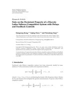
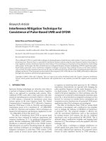
Figure 1: Positioning of pulses by a time-hopping code.
A disadvantage in receiver side equalisation is that RAKE
receivers, for instance, grow linearly in complexity with an
increase in the number of branches [13]. It has been proven
that in order to collect about half of the energy in a transmission, RAKE receivers with more than 10 taps are required
[20].
Transmitter side equalisation comprises of a shift in the
design complexity to the transmitter side. An ideal application would be in actuator networks, where remote nodes are
desired to be simple, inexpensive, and consuming minimal
power.
Alternate equalisation measures include a time-reversed
UWB adaptation whereby an MMSE equaliser is adopted
at the receiver to increase energy collection [21]; and a
receiver-side equalisation scheme encompassing MMSE decision feedback and the application of stochastic gradient descent algorithms [22].
2.2.
Receiver-side equalisation
The signal s(u) (t) transmitted for the uth user in a timehopped UWB system adopting a RAKE receiver, with equip(u)
robable data bm ∈ {−1, 1} mapped through binary PPM
with the time shift ε, is given by [23]
N −1
2.
SYSTEM EQUATIONS
s(u) (t) = ETX (u)
m=0
2.1. Equalisation methods
While the concept of channel equalisation does present benefits in terms of user error performance, it inevitably leads to
an increase in the level of complexity of the system. Increased
memory, channel tracking, and additional processing are a
few of the requirements, with the possibility of being incorporated into either the transmitter or the receiver.
Receiver side equalisation, which is more common in
wireless communications, entails the collection of channel
distorted energy, with increased receiver complexity. A RAKE
structure is common in UWB communications in order to
offset channel effects, with a branch dedicated to each arriving path encompassed in the decision process [17].
A common application of receiver equalisation is in sensor networks, where a collection of nodes each with one
or more environment sensors, communicate to higher level
node receivers which perform channel equalisation. This allows the sensor nodes to be simpler in design, also saving on
energy. Existing sensor network methods include “BTnodes”
[18] and Intel’s “Imote” [19], both high bandwidth methods
based upon bluetooth technology.
(u)
(u)
w t − mT f − cm Tc − εbm ,
(1)
where ETX (u) is the uth user’s signal energy, w(t) is the base
transmitted waveform of width Tm seconds, m is the frame
number, and N represents the number of symbols within a
single block of data. T f is a single frame length, which is
segmented into equally spaced intervals called “chips” of du(u)
ration Tc . Finally, cm denotes the position within the particular frame (the chip number) that is occupied by the uth
user’s signal in accordance with a time-hopping sequence. If
two users simultaneously occupy the same chip, a collision
or “hit” occurs. The characterising parameters of these codes
are the cardinality (Nh ), which specifies the alphabet size;
and the periodicity (N p ), which indicates the length of the
code before it is repeated. This time multiplexing is shown in
(u)
(u)
Figure 1, with cm ∈ , 0 ≤ cm ≤ Nh − 1. In the example,
(1)
(2)
(3)
cm = 0, cm = 4, cm = 6, and a frame of Nh = 11 chips is
used.
With the data shift ε, and the pulse duration Tm , the remaining frame duration is defined as the “guard time” Tg ,
where
Tg = Tc − ε + Tm .
(2)
K. Popovski et al.
3
×104
where x is the position of the receiver, and L is the number
of paths in the discrete version of the response. Path delay
τl is defined as τl = τ · l, where τ represents the time separation between multipath components. Coefficients αl (u; x)
encompass the channel energy, defined as
w(t)
10
5
0
L−1
−5
−0.25
−0.15
−0.05
0.05
0.15
EH,u;x =
0.25
(8)
l=0
Time (ns)
The received signal within a UWB system for Nu simultaneous users is defined as
0
Power
distribution (dB)
2
αl (u; x) .
N −1
Nu
r(t) =
−50
ETX (u)
u=1
m=0
(u)
(u)
w t − mT f − cm Tc − εbm
⊗ h(u; x, t) + n(t)
−100
0
1
2
3
4
5
6
7
8
9
N −1 L−1
Nu
10
=
Frequency (GHz)
ETX (u)
u=1
m=0 l=0
(u)
αl (u; x)w t − mT f − cm Tc
(u)
− εbm − τl + n(t),
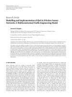
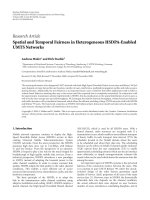
Figure 2: Time and frequency domain representations of a second
derivative Gaussian monocycle with centre frequency of 3.9 GHz.
This time is adjusted to permit a portion of the multipath
components to pass before the transmission of the next pulse.
Defining R as the data rate, and Ns the number of transmissions per symbol, the frame duration T f and chip duration
Tc can be written as
1
,
Ns R
1
.
Tc =
Nh Ns R
Tf =
(3)
(4)
For the purpose of this paper, the pulse shape was set as
the second derivative of the Gaussian pulse, with centre frequency f0 , defined as [24]
w(t) = 1 − 2 πt f0
2
exp − πt f0
2
,
(5)
f2
.
f02
(6)
with energy normalised Fourier transform of
W( f ) =
32π fo2
2
3
π fo2
f
f0
2
exp −
Figure 2 presents the time domain representation of
the energy normalised Gaussian waveform, with its corresponding power spectral density. A monocycle width of
0.5 nanosecond was selected, corresponding to a centre frequency of approximately 3.9 GHz.
Applying the standardised IEEE 802.15.3a UWB channel model, the discrete impulse response of the propagation
medium can be expressed as
L−1
h(u; x, t) =
αl (u; x)δ t − τl ,
l=0
(7)
(9)
where ⊗ represents convolution, and the channel is assumed
static over the transmission of each block of N frames. A
RAKE receiver combines the dispersed energy among NB of
the L received paths, thus requiring NB correlator branches,
each aligned in time with their respective multipath component. An All-RAKE receiver considers all replicas of the transmitted signal (NB = L); a Selective-RAKE receiver accounts
for NB < L paths, considering the NB paths with largest magnitude αl (u; x); and finally a Partial-RAKE receiver combines
energy from the first NB paths only (0 ≤ l < NB ).
This paper focuses on the performance of an All-RAKE
receiver.
2.3.
Transmitter-side equalisation
Within a TR-UWB scheme, the time reversed complex conjugate of the forward link channel response is used to diversify the signal before transmission. In order to draw a correspondence with an All-RAKE receiver structure, all L multipath components were incorporated into the transmit prefilter. An alternate prefilter design is presented in [25], based
upon a digital FIR filter.
The discrete representation of the time-reversed channel
is defined as
L−1
h(u; x, −t) = EH,u;x
βl (u; x)δ t − τl ,
(10)
l=0
where
βl = α(L−1)−l .
(11)
The channel response is assumed known at the transmitter
side. Estimation of the response can be achieved through the
use of the theory of reciprocity for antennas and electromagnetic propagation. It states that the outputs of nonlinear antennas for identical excitation signals, as detected at the other
4
EURASIP Journal on Wireless Communications and Networking
antenna, will be identical provided the medium between the
antennas is linear and isotropic [26]. Conversely, more accurate channel knowledge can be obtained through receiverside feedback to the transmitter.
The signal transmitted per user is given by
ETX (u)
EH,u;x
s(u) (t) =
TR
∞
m=−∞
(u)
(u)
w t − mT f − cm Tc − εbm
∗
⊗ h (u; x, −t)
∞
ETX (u)
EH,u;x m=−∞
=
L−1
(u)
βl (u; x)w t − mT f − cm Tc
l=0
(u)
− εbm − τl ,
(12)
where the division with EH,u;x is needed to normalise the energy of the channel response. This is to ensure that the energy
transmitted remains equal to ETX (u).
Without loss of generality, user 1 is taken as the desired
user, with the signal detected at its receiver in location x1
given by
Nu
rTR (t) =
s(u) (t) ⊗ h u; x1 , t
TR
+ n(t)
u=1
Nu
=
u=1
∞
ETX (u)
(u)
(u)
Rh(1)h(u) t − mT f − cm Tc − εbm
EH,u;x1 m=−∞
⊗ w(t) + n(t),
(13)
where
Rh(1)h(u) (t) = h 1; x1 , t ⊗ h∗ u; x1 , −t
(14)
is the correlation of the channel impulse responses from the
1st and the uth user to user 1’s receiver at location x1 . It
should be noted that all transmitters were assumed dispersed
enough such that the channel responses from each Nu transmitter to any receiver are independent. Additive white Gaussian noise with variance of N0 /2 is also present.
The decision variable (Z) is constructed through the
multiplication of the received signal with the receiver tem(u)
plate, giving the estimated received data of bm
(u)
(u)
ZTR
=
(m−1)T f +cm Tc +τ(L−1) +2Tm
(u)
(m−1)T f +cm Tc +τ(L−1)
(u)
× rTR (t)g t − (m − 1)T f + cm Tc + τ(L−1)
where
(u)
bm
=
⎧
⎨0,
⎩1,
dt,
(15)
It can be seen in (15) that there is an additional shift
of τL−1 for the integration, which is required to align the
template with the largest peak in the received signal of the
desired user. The (L − 1)th path is the in-phase autocorrelation peak position for the channel response, referred to
as the main lobe. The template g(t) was adapted for freespace propagation in order to draw an equivalence between
an All-RAKE dependent UWB system, and the time-reversed
method. When the guard time Tg is chosen such that ISI
is avoided, an All-RAKE-UWB and a TR-UWB system exhibit identical diversity orders and thus have the same error
performance, even in the presence of multiuser interference
(MUI). However, temporal focusing allows TR-UWB to be
more resilient in the presence of ISI, as will be shown through
simulation in Section 4.
With the received signal taking the form of the autocorrelation of the channel impulse response, it can be inferred
that inherent sidelobe energy will exist. Following from this,
it can be seen that increasing the randomness of a channel
response results in lower sidelobe energy. Thus, an NLOS
system is expected to out-perform an LOS system. However,
larger lengths of the NLOS channels will ultimately lead to an
increase in the duration of the sidelobe energy.
While not studied in this paper, a TR-UWB system may
adopt only a portion of the channel response as the signal
prefilter. An analysis into time-reversed systems utilising only
selected paths of the channel, also referred to as “dynamic
TR,” can be found in [6, 15].
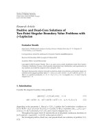
For a further comparison between transmitter- and
receiver-side equalisation, consider the system models for
UWB and TR-UWB in Figures 3(a)–3(d). It can be noted
that the main variations are the added prefiltering in
the TR-UWB transmitter, and subsequently simplified receiver structure relative to the NB branch RAKE receiver in
Figure 3(b). For brevity, frame- and time-hopping shifts have
been omitted in the receiver structures.
Hereafter, a chip synchronous single-input-single-output
(SISO) system is considered, assuming that the transmit and
receive antennas, which would act as pulse shaping filters,
have no significant combined effect on the signal transmitted. Time-reversal properties also apply in an SISO system,
assuming that the bandwidth occupied by transmissions is
much larger than the correlation frequency exhibited by the
channel [27]. Also, a quasistationary channel is assumed,
such that it remains time-invariant for the transmission of
a full UWB packet. Calculations are based upon the CM1
channel scenario of the 802.15.3a model, characterised for
an LOS system with a 0–4 m separation between all transmit
and receive pairs.
3.
3.1.
Z ≥ 0,
Z < 0,
g(t) = w(t) − w(t − ε).
(16)
(17)
ERROR PERFORMANCE ANALYSIS
Time-hopping code analysis
With all users assumed to be transmitting the same level of
energy, and influenced by the same channel model, the remaining influential factor on the level of intersymbol and
K. Popovski et al.
5
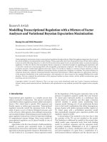
(u)
w(t − mT f )
w(t − mT f − cm Tc )
m
m
m
Data
encoder
TH sequence
delay
δ(t − mT f ) Pulse correlator
W( f )
s(u) (t)
(a)
N s −1
r(t)g(t − τn )
RAKE branch (1)
r(t)
RAKE branch (2)
.
.
.
n=0
Polarity
detector
Integrator
+
(u)
bm
N s −1
Z (u) =
t n=0
RAKE branch (NB )
r(t)g(t − τn )
(b)
(u)
w(t − mT f )
δ(t − mT f )
m
Pulse correlator
W( f )
(u)
w(t − mT f − cm Tc − εbm )
m
m
TH sequence
delay
Prefiltering
H −1 ( f )
Data
encoder
(u)
sTR (t)
(u)
w(t − mT f − cm Tc )
m
(c)
Z (u) =
r(t)g(t − τL−1 )
r(t)
RAKE branch
t
r(t)g(t − τL−1 )
Polarity
detector
Integrator
(u)
bm
(d)
Figure 3: System model for (a) UWB transmitter, (b) UWB receiver, (c) TR-UWB transmitter, and (d) TR-UWB receiver.
multiuser interference is the time-hopping code. The cardinality of the hopping code is generally chosen to be equal to
the number of chips within a single frame (Ns ). In order to
predict the performance of a perfectly power controlled system, the hopping code itself must be analysed.
Intersymbol and multiuser interferences are affected by
the separation between consecutive elements within sequences. These indicate the number of intermediary chips
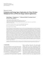
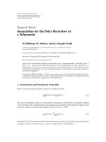
between transmissions by a single user for ISI and chip separations between different users for MUI. Figure 4 illustrates
the ISI separation for two transmissions, separated by A
frames.
The chip separation probability (Se (A, B)) is determined
for a certain separation B between transmissions, where A
represents the number of intermediate frames. The issue of
intermediate pulses over the separation distance is important
since the RMS delay spread of a signal may cause intersymbol interference well over an adjacent frame. These probabilities are determined through a brute force analysis of the
(u)
hopping code (cm ) used for multiuser encoding, averaged
over the all codes within each family of sequences. Evaluated
state probabilities for the given A are [p1 , p2 , . . . , p2(Nh −1)+1 ],
where Se (A, B) = pB . For ISI, each code within a sequence
Tf
AT f
Tc
(1)
cm
(1)
A frames
cm+1+A
+
B chips
Figure 4: Symbol separations.
family is analysed separately, while for MUI all possible sequence pairs are considered.
Probabilities are significantly dependent upon the cardinality (Nh ) of the hopping code. A larger value will result in
more chips to select from, leading to a more sparse profile.
The separation between any two user transmissions ranges
from ANh to (A + 2)Nh − 2, where A is zero for adjoining
frames.
This paper focuses on Reed-Solomon [28] and linear
congruence [29] hopping codes. A discussion on the relative performance of various sequences in a time-hopped environment can be found in [30]. The ISI chip separation
6
EURASIP Journal on Wireless Communications and Networking
0.1
Probability of chip separation
0.09
0.08
0.07
0.06
0.05
0.04
0.03
0.02
0.01
0
0
2
4
6
8
10
12
14
16
18
20
Chip separation between consecutive sequence elements
(a)
(2Lτ), allowing enough time for the multipath components
to pass.
In order to estimate the performance of a TR-UWB system operating in a scattering environment, the expected ISI
variance may be determined. This is accomplished by estimating the level of interference for a single transmission,
summed over all overlapping adjacent transmissions by the
same user. In order to obtain a close approximation, the ISI
must be Gaussian distributed.
The ISI estimation in this paper takes an average on the ε
shift introduced for the encoding of data. Assuming indepen(u)
dent identically distributed random variables for bm , this average is equivalent to no data modulation shift.
With the received signal comprised of Gaussian waveforms, which ideally have a zero average, the ISI has an expected mean of zero. This reduces the variance calculation
to
σ 2 ≡ (Y − μ)2 = Y 2 ,
0.1
Probability of chip separation
0.09
0.08
0.07
0.06
0.05
0.04
0.03
0.02
0.01
0
0
2
4
6
8
10
12
14
16
18
20
Chip separation between consecutive sequence elements
(18)
where μ represents the signal mean, and · an ensemble average. The variance is calculated over all overlapping transmissions, also over all possible chip separations by applying
the probabilities determined in Section 3.1.
The formula for the variance of the ISI, averaged over
N transmissions, is given by (19), which accounts for interference from preceding transmissions (Pre ISI) and following transmissions (Post ISI). Parameters Nw and Nl define the number of paths expected to overlap for the preand post-transmission ISI, respectively, with Nov representing the number of adjacent frames over which the transmitted signal will exist. It should be noted that the transmission channel and the prefiltering channel are identical for
ISI;
(b)
Nov (2(Nh −1)+1)
2
σISI =
Figure 5: Chip separation probabilities for (a) Reed-Solomon and
(b) linear congruence codes.
χσ,ζ,ξ + χσ,ζ,ψ ,
(19)
σ=1
σ =1
where
probabilities for these sequence families for a cardinality of
Nh = 11, no intermediary pulses (A = 0), and separation
ranging from 0 to 2Nh − 2 are given in Figures 5(a) and 5(b),
respectively.
χσ,ζ,ν = Se (σ − 1, σ) · var h 1; x1 , t ⊗
L−1
ξ=
βk+1 w t − τk−Nw ,
k=Nw
3.2. Intersymbol interference
Nl −1
ψ=
Considering typical RMS delay spread for a UWB multipath channel, intersymbol interference may cause a significant degradation. This is particularly evident in TR-UWB
systems, with a larger transmitted waveform close to doubling the length of the received signal. ISI is affected by the
width of the transmitted pulses, and the data rate. The level
of interference will diminish to zero provided that the chip
time is greater than twice the length of the channel response
βk+1 w t − τk+Nw ,
k=0
Nw =
(σ − 1)T f + σTc
,
τ
Nl = L − Nw ,
Nov =
Lτ
.
Tf
ETX (1)
·ν
EH,1;x1
,
K. Popovski et al.
7
Here, ν represents the portion of the transmitted signal
which is regarded as ISI, and is referred to as the third parameter of χσ,ζ,ν . This formula converges to an ISI variance within
5% of the final value when averaged over approximately 50
iterations.
Within an environment where multiple users operate in
close proximity, there is the possibility of interuser interference. For the case of ISI, if the chip time Tc is greater
than the transmission duration Lτ, interference is of no concern. For MUI, this condition would only remove the partial interference caused by transmissions in adjacent chips,
while the issue of same chip collisions between users remains. For a multiuser scenario, there are three types of
interference which must be accounted for: in-phase, where
two users transmit in the same chip; pre-out-of-phase, interference caused by signals in previous chips; and postout-of-phase, interference caused by signals in subsequent
chips.
The first is dependent upon the separation probabilities
of user asynchronisation within a single frame; while the latter two are dependent upon possible separations between
users for frames over which a transmission exists. Since user
asynchronisation is assumed uniform, the separation probability vector Se (A, B) will be identical for in-phase and outof-phase interference.
The MUI variance estimation presented here accounts
for the interference by a single user only, with the result scaled. The in-phase variance given by (20) encompasses interference from transmissions within the same
frame as the desired user. Only the partial overlap is considered for each possible separation Θ, determined as in
the ISI case by the parameters Nw(In) , which represents
the number of paths before an overlap of the preinterference occurs; and Nl(In) , which indicates the number of
paths which are overlapping for post-interference. The outof-phase MUI expression in (21) accounts for overlapping
from frames adjacent to the desired user’s transmission. For
each MUI type, the expected interference signal is convoluted with the channel response from the interferer to the
desired user’s receiver at position x1 , and the energy normalised;
Nh −1
0
χΘ,ξ +
Θ=−(Nh −1)
Θ=1
χΘ,ψ ,
(20)
where
χΘ,ν = Se 0, Θ+ Nh − 1 +1 · var h u; x1 , t ⊗
L−1
ξ=
βk+1 w t − τk−Nw(In) ,
k=Nw(In)
Nov (2(Nh −1)+1)
2
σOutPhaseMUI =
βk+1 w t − τk+Nw(In) .
k=0
(21)
σ=1
ETX (u)
·ν ,
EH,u;x1
χσ,ζ,ν = Se (0, σ) · var h u; x1 , t ⊗
ETX (u)
·ν
EH,u;x1
,
L−1
ξ=
βk+1 w t − τk−Nw(Out) ,
k=Nw(Out)
Nl(Out) −1
ψ=
βk+1 w t − τk+Nw(Out) ,
k=0
with
Nw(In) = −Θ ·
Tc
,
τ
Nl(In) = L − Nw(In) ,
Nw(Out) =
(σ − 1)T f + σTc
,
τ
Nl(Out) = L − Nw(Out) ,
Nov =
Lτ
.
Tf
Thus the final variance formula equates to the expected interference from a single interferer, multiplied by the number
of interferers, evaluated as
2
2
2
σMUI = σInPhaseMUI + σOutPhaseMUI · Nu − 1 .
(22)
Through testing, it was determined that an MUI variance
within 5% of the final value could be obtained after approximately 100 iterations.
The Nl , Nw , and Nov path alignment parameter variations for both ISI and MUI formulation are illustrated in
Figure 6, with a time-reversed transmission approximated by
a triangular waveform. Three consecutive chip aligned transmissions are shown for a single user, together with randomly
shifted transmissions from one interfering user (u = 1). The
dark shading represents the desired signal, while the light
shading indicates the interference sources from both ISI and
MUI.
3.4.
Error analysis
For a binary PPM UWB system sending Ns transmissions per
symbol, the probability of error is determined through [31]
Nl(In) −1
ψ=
χσ,ζ,ξ + χσ,ζ,ψ ,
σ =1
where
3.3. Multiuser interference
2
σInPhaseMUI =
For the out-of-phase counterpart
Pe = Q
1
Ns · SINR = erfc
2
Ns · SINR
,
2
(23)
8
EURASIP Journal on Wireless Communications and Networking
Pre-ISI
100
Post-ISI
Nov T f
10−1
User 1
Nw τ
Tf
Nw(Out) τ
BER
10−2
Nl τ
10−3
Nl(Out) τ
10−4
User u
10−5
0
5
10
15
20
25
SNR (dB)
Nl(In) τ
All-RAKE - 10 users
All-RAKE - 2 users
Out-of-phase MUI In-phase MUI Out-of-phase MUI
TR-UWB - 10 users
TR-UWB - 2 users
Figure 6: Path alignment parameters for ISI and MUI variance formulation.
Figure 7: Similarity analysis of UWB and TR-UWB in the absence
of ISI at 3 Mbit/s, Ns = 1.
where SINR represents the signal-to-combined noise, ISI,
and MUI ratio. Note that this is for “soft” signal reception,
where the signal formed by Ns pulses is observed as a single
multi-pulse transmission. This is in contrast to “hard” signal
detection, where independent decisions are computed over
each of the Ns transmissions, and then a majority criterion
applied to determine the encoded data [32].
In order for (23) to hold, it must be true that all parameters of the SINR are Gaussian distributed. The additive white
noise exhibited by the system is defined as a statistically independent zero mean Gaussian random variable. The ISI and
MUI terms may be brought under the standard Gaussian approximation provided that the number of paths within the
channel impulse responses, the number of transmissions per
symbol, the number of interfering users, and bit rate for all
transmitters are sufficiently large [33]. For all testing purposes, the number of paths within the channel responses was
set at 40, and a maximum of 10 users were tested. Since the
noise and interference terms are assumed Gaussian, and the
signal transmitted is deterministic, the received signal is also
Gaussian distributed.
Although the received signal power PRX (u) may arrive
at the receiver, only the power in the main autocorrelation
peak is used for data decoding ((L−1)th path). This is accounted for by an additional ratio “φ,” determined by observing the ratio of main path to sidelobe power over several tests. For the LOS, 0–4 m channel scenario of the IEEE
802.15.3a model, φ ≈ 0.566, averaged over 50 independent
realisations of the model. The final SINR is
4.
SINR =
φ · PRX (u)
,
2
2
2
σISI + σMUI + σAWGN
2
with σMUI = 0 for a single user system.
(24)
COMPARISON OF SIMULATED AND
ESTIMATED RESULTS
All-RAKE and TR-UWB simulations were adapted from a
time hopped PPM UWB simulation by Di Benedetto and
Giancola [32]. The cardinality and periodicity of each time
hopping code were set to 11, with a pulse width Tm of
0.5 nanosecond, and a data encoding shift ε of 0.5 nanosecond. The multipath time separation parameter τ was set to
1 nanosecond, chosen to be greater than the base waveform
width, and to allow an encoded signal to be orthogonal to its
nonencoded counterpart. All users had equal transmit powers of 1 mW, and equal data rates which were adjusted by
changing the frame width T f . The packet size was set constant at 1024 octets.
In order to ensure the equivalence of the UWB and TRUWB models in the absence of ISI, simulations were conducted at a data rate of 3 Mbit/s, Ns = 1, for 2 and 10 users,
with results shown in Figure 7. This data rate and Ns combination allows the majority of the 40 nanoseconds channel
response tested to pass before the transmission of the next
symbol. Equality between the two methods is shown in the
presence of varied MUI, where the use of time hopping allows the system to exhibit a comparatively reasonable performance for a 10-user scenario.
The ISI variance equation was tested by observing the
performance of a simulated single user scenario. Resulting error rates using Reed-Solomon time hopping for the
All-RAKE and TR-UWB simulations, together with the TRUWB variance equation (“TR-Equ”), are shown in Figures
8 and 9 for an Ns of 5 and 10, respectively. It can be observed that for all tested data rates, the semianalytical analysis closely traces the simulated performance. Also, equivalent All-RAKE based systems exhibit severely impaired performance in the presence of increased ISI. This difference
K. Popovski et al.
9
10−1
10−1
10−2
10−2
BER
BER
10−3
10−4
10−5
10−3
10−4
10−6
10−7
0
5
10
15
20
10−5
25
0
5
10
SNR (dB)
15
20
25
SNR (dB)
All-RAKE - 15 Mbit/s
All-RAKE - 50 Mbit/s
All-RAKE - 100 Mbit/s
TR-UWB - 15 Mbit/s
TR-UWB - 50 Mbit/s
TR-UWB - 100 Mbit/s
TR-Equ - 15 Mbit/s
TR-Equ - 50 Mbit/s
TR-Equ - 100 Mbit/s
All-RAKE - maximum
All-RAKE - average
All-RAKE - minimum
TR-UWB - maximum
Figure 8: BER curves for ISI with Reed-Solomon coding (Ns = 5).
TR-UWB - average
TR-UWB - minimum
TR-Equ - 30 Mbit/s
Figure 10: BER curves for ISI and MUI for Reed-Solomon coding
at 30 Mbit/s, Ns = 5.
10−1
10−1
10−2
BER
BER
10−3
10−4
10−2
10−5
10−6
10−7
0
5
10
15
20
25
SNR (dB)
All-RAKE - 50 Mbit/s
All-RAKE - 100 Mbit/s
TR-UWB - 50 Mbit/s
10−3
0
5
10
15
20
25
SNR (dB)
TR-UWB - 100 Mbit/s
TR-Equ - 50 Mbit/s
TR-Equ - 100 Mbit/s
All-RAKE - maximum
All-RAKE - average
All-RAKE - minimum
TR-UWB - maximum
TR-UWB - average
TR-UWB - minimum
TR-Equ - 30 Mbit/s
Figure 9: BER curves for ISI with Reed-Solomon coding (Ns = 10).
Figure 11: BER curves for ISI and MUI for Reed-Solomon coding
at 30 Mbit/s, Ns = 10.
intensifies for higher data rates, which leads to a proportional
elevation in the level of ISI. These results are supported by
RAKE and TR-UWB tests in the presence of ISI conducted in
[25].
Through (3), it was seen that the parameter Ns also affects
the frame length. At a data rate of 100 Mbit/s, the ISI plateau
is clearly visible. For Ns = 5, the formulated plateau occurs
at approximately 10−6 , while for Ns = 10 it appears at nearly
10−4 .
MUI variance tests were conducted at a data rate of
30 Mbit/s, with Ns = 5 and 10. Results are illustrated in Figures 10 and 11. The plots indicate the maximum, minimum,
and average BER rates over all users for both All-RAKE and
TR-UWB simulations, and also the average performance as
based on the TR-UWB variance formulas. It is evident that
the formulated curve closely follows the average simulated
performance. At 30 Mbit/s, Ns = 10, it can be seen that
the derived curve follows the median of the maximum and
10
EURASIP Journal on Wireless Communications and Networking
10−1
10−2
BER
10−3
10−4
10−5
10−6
0
5
10
15
20
25
SNR (dB)
TR-UWB - 10 users
TR-Equ - 1 user
TR-Equ - 10 users
All-RAKE - 1 user
All-RAKE - 10 users
TR-UWB - 1 user
In order to examine the performance of this system with
varied hopping schemes, “linear congruence” hopping codes
were also tested. Results for 1 and 10 user tests, at a data rate
of 30 Mbit/s and Ns = 5, are shown in Figure 12. The equivalence between the formulated and simulated results can be
seen. While the maximum and minimum error rates for the
10-user case are not shown, an alignment with the average
BER is apparent. The prevailing difference in performance
between All-RAKE and TR-UWB is once again evident.
Figure 13 indicates the effects of MUI on the expected
performance of a time reversed system at 30 Mbit/s, Ns = 5,
with a signal-to-noise ratio of 12 dB. The addition of each
user results in an increase in the level of MUI present, following a near exponential rise in the error rate. Although a
time-reversed system does have the benefit of mitigating ISI,
further measures are required to reduce the degrading effects
of interfering users.
5.
Figure 12: BER curves for 1-user and 10-user cases with linear congruence coding at 30 Mbit/s, Ns = 5.
×10−3
4
3.5
3
BER
2.5
2
1.5
1
0.5
0
1
2
3
4
5
6
7
8
9
10
Number of users
Figure 13: BER versus number of users at 12 dB, 30 Mbit/s, Ns = 5.
CONCLUSIONS
While a TR-UWB system does require increased processing
at the transmitter side, it removes much of the burden from
the receiver, and allows more robust operation in the presence of ISI. While this may only be a shift of requirement
in a single-transmitter single-receiver system, it has significant benefits in single-transmitter multiple-receiver circumstances, such as cluster-based wireless actuator networks.
Through simulation, it was determined that derived
equations for the variance of ISI and MUI closely follow
expected results. Variance formulae take into consideration
separation between user transmissions, together with chip
separation probabilities, for both signal degradations. The
capabilities of TR-UWB in mitigating ISI to a certain degree
were shown, although exhibiting larger variance between
user error performances in a multiuser case when compared
to a system using an All-RAKE receiver.
Future work that can be conducted in this area includes
independent transmitter-based time filtration to decrease the
effect of multiuser interference on system performance. Also,
a study into the validity of the Gaussian approximation assumed for varied system parameters, and the possibility of
time-hopping code design based upon chip separation probability analysis, can be envisaged.
REFERENCES
minimum error rates. Due to MUI being dominant relative
to ISI in the scenarios tested, there is a closer correspondence
between All-RAKE and TR-UWB error rates than in a single
user system, with errors due to ISI effects only.
Figures 10 and 11 also illustrate an interesting property
about the variance between user performance in transmitter and receiver side equalisation types. While achieving relatively better performance, TR-UWB exhibits severe variations in the error probabilities between users. On the contrary, All-RAKE based UWB has a much fairer error distribution, although all users having relatively worse performance
than a time reversed system.
[1] FCC News, “New Public Safety Applications and Broadband
Internet Access among uses Envisioned by FCC Authorization
of Ultra-Wideband Technology,” Unofficial Announcement of
Commission action, February 2002.
[2] FCC Document 00-163, “Revision of Part 15 of the Commission’s Rules Regarding Ultra-Wideband Transmission Systems,” April 2002, ET Docket No. 98-153.
[3] S. Lemon, “Standards deadlock hits UWB—the market will
have to decide,” IDG News Service, May 2005 http://www
.techworld.com/applications/news/index.cfm?NewsID=3674.
[4] S. Deffree, “No standard for ultra wideband comms,” January
2006, Electronic News, />
K. Popovski et al.
[5] G. F. Edelmann, T. Akal, W. S. Hodgkiss, S. Kim, W. A. Kuperman, and H. C. Song, “An initial demonstration of underwater
acoustic communication using time reversal,” IEEE Journal of
Oceanic Engineering, vol. 27, no. 3, pp. 602–609, 2002.
[6] K. Usuda, H. Zhang, and M. Nakagawa, “Pre-Rake performance for pulse based UWB system in a standardized UWB
short-range channel,” in Proceedings of IEEE Wireless Communications and Networking Conference (WCNC ’04), vol. 2, pp.
920–925, Atlanta, Ga, USA, March 2004.
[7] S. M. Emami, J. Hansen, A. D. Kim, et al., “Predicted Time Reversal Performance in Wireless Communications Using Channel Measurements,” IEEE COMLET, 2002,
.ethz.ch/commth/pubs/files/TRComLet.pdf.
[8] R. C. Qiu, H. Liu, and X. Shen, “Ultra-wideband for multiple access communications,” IEEE Communications Magazine,
vol. 43, no. 2, pp. 80–87, 2005.
[9] T. Strohmer, M. Emami, J. Hansen, G. Papanicolaou, and A.
J. Paulraj, “Application of time-reversal with MMSE equalizer to UWB communications,” in Proceedings of IEEE Global
Telecommunications Conference (GLOBECOM ’04), vol. 5, pp.
3123–3127, Dallas, Tex, USA, November-December 2004.
[10] M. Fink, “Time-reversed acoustics,” Scientific American,
vol. 281, pp. 91–97, 1999.
[11] G. Yue, L. Ge, and S. Li, “Performance of UWB time-hopping
spread-spectrum impulse radio in multipath environments,”
in Proceedings of the 57th IEEE Semiannual Vehicular Technology Conference (VTC ’03), vol. 3, pp. 1644–1648, Jeju, Korea,
April 2003.
[12] J. Foerster, “Channel modelling sub-committee report final,”
Report IEEE 802.15.SG3a, IEEE, New York, NY, USA, December 2002.
[13] M. Chen and X. Li, “Transmitter-based channel equalization
and MUI suppression for UWB systems,” in Proceedings of
the International Conference on Modern Problems of Radio Engineering, Telecommunications and Computer Science (TCSET
’04), pp. 501–504, Lviv-Slavsko, Ukraine, February 2004.
[14] A. E. Akogun, R. C. Qiu, and N. Guo, “Demonstrating time reversal in ultra-wideband communications using time domain
measurements,” in Proceedings of the 51st International Instrumentation Symposium, pp. 737–742, Knoxville, Tenn, USA,
May 2005.
[15] A. Derode, A. Tourin, and M. Fink, “Random multiple scattering of ultrasound. II. Is time reversal a self-averaging process?”
Physical Review E, vol. 64, no. 3, Article ID 036606, 13 pages,
2001.
[16] S. Zhao and H. Liu, “Prerake diversity combining for pulsed
UWB systems considering realistic channels with pulse overlapping and narrow-band interference,” in Proceedings of
IEEE Global Telecommunications Conference (GLOBECOM
’05), vol. 6, pp. 3784–3788, St. Louis, Mo, USA, NovemberDecember 2005.
[17] M. Z. Win and Z. A. Kostic, “Virtual path analysis of selective
Rake receiver in dense multipath channels,” IEEE Communications Letters, vol. 3, no. 11, pp. 308–310, 1999.
[18] ETH Zurich, “BTnodes—A Distributed Environment for
Prototyping Ad Hoc Networks,” 2005, ode
.ethz.ch/.
[19] Intel Corporation, “Intel Mote 2 Overview,” 2005, http://www
.intel.com/research/downloads/imote overview.pdf.
[20] M. Z. Win and R. A. Scholtz, “On the energy capture of ultrawide bandwidth signals in dense multipath environments,”
IEEE Communications Letters, vol. 2, no. 9, pp. 245–247, 1998.
[21] T. Strohmer, M. Emami, J. Hansen, G. Papanicolaou, and A.
J. Paulraj, “Application of time-reversal with MMSE equal-
11
[22]
[23]
[24]
[25]
[26]
[27]
[28]
[29]
[30]
[31]
[32]
[33]
izer to UWB communications,” in Proceedings of IEEE Global
Telecommunications Conference (GLOBECOM ’04), vol. 5, pp.
3123–3127, Dallas, Tex, USA, November-December 2004.
A. G. Klein and C. R. Johnson Jr., “MMSE decision feedback equalization of pulse position modulated signals,” in Proceedings of IEEE International Conference on Communications
(ICC ’04), vol. 5, pp. 2648–2652, Paris, France, June 2004.
T. Erseghe, “Time-hopping patterns derived from permutation sequences for ultra-wide-band impulse-radio applications,” in Proceedings of the 6th WSEAS International Conference on Communications, vol. 1, no. 1, pp. 109–115, Crete,
Greece, July 2002.
A. Swami, B. Sadler, and J. Turner, “On the coexistence of
ultra-wideband and narrowband radio systems,” in Proceedings of IEEE Military Communications Conference on Communications for Network-Centric Operations: Creating the Information Force (MILCOM ’01), vol. 1, pp. 16–19, McLean, Va,
USA, October 2001.
N. Guo, R. C. Qiu, and B. M. Sadler, “An ultra-wideband autocorrelation demodulation scheme with low-complexity time
reversal enhancement,” in Proceedings of IEEE Military Communications Conference (MILCOM ’05), vol. 5, pp. 3066–3072,
Atlantic City, NJ, USA, October 2005.
C. A. Balanis, Antenna Theory: Analysis and Design, John Wiley
& Sons, New York, NY, USA, 2nd edition, 1997.
A. Derode, A. Tourin, J. de Rosny, M. Tanter, S. Yon, and
M. Fink, “Taking advantage of multiple scattering to communicate with time-reversal antennas,” Physical Review Letters,
vol. 90, no. 1, Article ID 014301, 4 pages, 2003.
R. M. Mersereau and T. S. Seay, “Multiple access frequency
hopping patterns with low ambiguity,” IEEE Transactions on
Aerospace and Electronic Systems, vol. 17, no. 4, pp. 571–578,
1981.
A. V. Jovancevic and E. L. Titlebaum, “New coding schemes for
increased number of users or messages in frequency-hopped
multilevel FSK,” in Proceedings of the 46th IEEE Vehicular Technology Conference (VTC ’96), ‘Mobile Technology for the Human Race’, vol. 3, pp. 1732–1735, Atlanta, Ga, USA, April-May
1996.
K. Popovski, B. J. Wysocki, and T. A. Wysocki, “Performance
comparison of UWB hopping codes in a multi-user rich scattering environment,” in Proceedings of the 63rd IEEE Vehicular
Technology Conference (VTC ’06), vol. 4, pp. 1864–1868, Melbourne, Australia, May 2006.
J. G. Proakis and M. Salehi, Communication Systems Engineering, chapter 7, Prentice-Hall, Englewood Cliffs, NJ, USA,
2nd edition, 2002.
M-.G. Di Benedetto and G. Giancola, Understanding Ultra
Wide Band Radio Fundamentals, Prentice-Hall Professional
Technical Reference, Englewood Cliffs, NJ, USA, 2004.
M.-G. Di Benedetto, “MAC for UWB,” Networking with UWB
- UWB Group at University of Rome, a
.edu/∼spapl/seminar/uwb2.pdf.