Báo cáo hóa học: " Research Article Modified Isochronous Coordination Function for Enhancement of VoIP Call Capacity over IEEE 802.11 WLAN" pptx
Bạn đang xem bản rút gọn của tài liệu. Xem và tải ngay bản đầy đủ của tài liệu tại đây (699.85 KB, 8 trang )
Hindawi Publishing Corporation
EURASIP Journal on Wireless Communications and Networking
Volume 2008, Article ID 218076, 8 pages
doi:10.1155/2008/218076
Research Article
Modified Isochronous Coordination Function for
Enhancement of VoIP Call Capacity over IEEE 802.11 WLAN
Sanjaya Gupta, Vijay Sahu, and Brejesh Lall
Department of Electrical Engineering, Indian Institute of Technology Delhi, Hauz Khas, New Delhi 110016, India
Correspondence should be addressed to Brejesh Lall,
Received 17 March 2007; Revised 20 August 2007; Accepted 22 October 2007
Recommended by Kameswara Rao Namuduri
VoIP over IEEE 802.11 wireless local area network (WLAN) is growing very fast and is providing a cost effective alternative for
voice communications. WLANs were initially set up to handle bursty nonreal time type of data traffic. Therefore, the wireless access
protocols initially defined are not suitable for voice traffic. Subsequently, updates in the standard have been made to provision for
QoS requirements of data, especially the real time traffic of the type voice and video. Despite these updates, however, transmitting
voice traffic over WLAN does not utilize the available bandwidth (BW) efficiently, and the number of simultaneous calls supported
in practice is significantly lower than what the BW figures would suggest. Several modifications have been proposed to improve the
call capacity, and recently isochronous coordination function (ICF) was introduced to mitigate the problem of low call capacity. In
this paper, we propose a modified ICF which further improves the performance in terms of the call capacity. The proposed scheme
uses multiplexing and multicasting in the downlink to substantially increase the call capacity.
Copyright © 2008 Sanjaya Gupta et al. This is an open access article distributed under the Creative Commons Attribution License,
which permits unrestricted use, distribution, and reproduction in any medium, provided the original work is properly cited.
1. INTRODUCTION
VoIP over WLAN is becoming a very attractive solution for
wireless voice communications. One of the reasons for the
huge interest in VoWLAN is the potential of the WLANs
to bypass the local loop of the traditional telephone system
(PSTN). The calls can therefore enter into a well-connected
IP network directly through WLAN. The other reason is that
WLANs are widely available and easy to deploy. This technol-
ogy uses the existing packet-switched data network for trans-
porting the packets and provides a low-cost alternative to the
traditional telephone system. Wireless LAN standard 802.11
specifies two modes for wireless channel access. These are
distributed coordination function (DCF) [1] and point coor-
dination function (PCF) [1]. DCF mode is based on random
access of channel that is best suited for nonreal-time traf-
fic, that is, bursty traffic, and PCF mode is based on polling
mechanism that is best suited for real-time traffic. However,
most of the early devices do not support PCF mode.
During early years of WLAN deployment, mostly the
DCF mode was supported in WLAN devices, but in recent
years, the importance of the PCF mode is being recognized
and now the PCF mode is also being supported [12–14]in
new devices like laptops, personal digital assistants (PDAs).
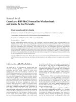
The DCF mode is based on carrier sense multiple access
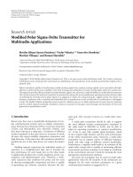
with collision avoidance (CSMA/CA). The timing diagram
of DCF scheme is depicted in Figure 1.
In the DCF mode [1], control to the access of channel is
distributed among all the stations. The DCF access method is
based on the CSMA/CA principle in which a host, wishing to
transmit, senses the channel to check if it is free. On finding
the channel free, the host waits for a random amount of time
(to avoid two hosts starting transmission at the same time)
before transmitting.
In the PCF mode [1] of operation, the access of the wire-
less channel is centralized by a polling-based protocol con-
trolled by the point coordinator (PC). The access points
(APs) generally serve as PCs. The PCF mode provides
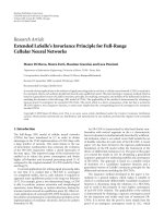
contention-free service to the wireless stations. In PCF mode,
a frame is divided in two parts: contention-free period (CFP)
and contention period (CF). The PC indicates the start of the
contention-free period by sending a beacon frame that con-
tains the list of pollable stations and other polling manage-
ment information. The CFP is repeated after a fixed inter-
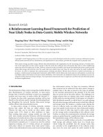
val. The CFP and CP together constitute a superframe whose
structure is shown in Figure 2(a).
2 EURASIP Journal on Wireless Communications and Networking
As shown in Figure 2(b), after sending the beacon, the
PC starts polling stations one by one in the order indicated
in the beacon. In CFP, if the PC has a data packet to send to
a station, it sends the polling packet piggybacked on the data
packet, and if the PC does not have any data to send, then
it sends only a polling packet. The polled station responds
by sending the uplink ACK packet and piggybacks any up-
link data on the ACK packet. If polled station does not have
data to send in the uplink, then it just sends a null packet
in response to the poll by PC. In this scheme, some of the
bandwidth is used only for polling and ACK, and hence it is
wasted. Here, in Figure 2(b), stations P3 and P4 do not have
any uplink and downlink data, but even then the PC polls
these stations resulting in wastage of bandwidth.
These drawbacks of the basic PCF mode limit the num-
ber of simultaneous VoIP calls. There are several proposals
given by various authors, like dynamic PCF [11], modified
PCF [6], adaptive PCF [8], and so forth, which improve call
capacity. These proposals seek to overcome the call capac-
ity deficiencies of the PCF mode of operation, thereby pro-
viding capability to the WLAN network to accommodate a
larger number of simultaneous VoIP calls. One of the pro-
posed techniques introduces a new modified multiple access
mechanism termed as isochronous coordination function [9]
to improve the capacity.
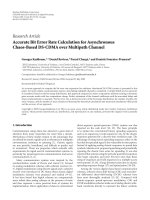
2. ICF OVERVIEW
Isochronous coordination function was introduced to han-
dle constant bit-rate real-time traffic, especially voice traffic.
It aims to provide a dynamic time division multiple access-
(TDMA-) like service for transporting voice packets effi-
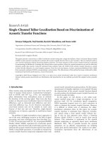
ciently [9]. The ICF-poll frame includes a status vector (SV),
which is a string of polling bits, one for each admitted voice
station. These polling bits are assigned to each station at the
time of connection setup with the AP. In each ICF cycle, voice
stations transmit in assigned time slots, as shown in Figure 3.
Based on its polling position and the status of other stations,
as indicated by the SV in the ICF-poll frame, an active sta-
tion determines its time slot (if any) in the ICF cycle. In the
SV, a “1” polling bit indicates that the corresponding sta-
tion may transmit a voice packet in the current cycle and
vice versa. This scheme aims to exploit voice trafficcorre-
lation to obtain a tradeoff between call capacity and loss ra-
tio. Voice traffic is correlated to some extent and therefore
voice data corresponding to some lost packets can be recon-
structed from the received voice packets. Studies have shown
that in order to provide acceptable quality of service, the lost
packet number should not be greater than 1% [5] of the to-
tal number of packets sent by a particular station. This char-
acteristic of voice traffic is exploited by the ICF technique
which provides a mechanism to trade off delay with packet
loss. ICF uses fixed-size time slots for scheduling trafficand
this type of scheduling mirrors isochronous trafficpattern
exactly. However, fixed-size packet implies that speech frame
can no longer be buffered and it has to be dropped if a time
slot is not made available to a particular station in a given
superframe. The procedure for slot allocation is such that
Table 1
Codec
Packet Payload
duration (ms) size (bytes)
G.711 20 160
G.726 20 160
G.723.1 30 20/24
GSM (13.2 kbps) 20 33
it maximizes the number of users supported while ensuring
that the packet loss for any user is not greater than 1%.
Due to the limited number of time slots in an ICF cycle,
all stations may not be polled, so an efficient polling list man-
agement is implemented by using cyclic polling queue [9].
Due to the time-sensitive but loss-tolerable nature of voice,
the unpolled stations (which do not get time slot in ICF cycle
for transmission) drop one packet. When such a packet drop
takes place, then this particular station is provided higher
priority in slot allocation when the polling queue is updated
for the next superframe. This is done to ensure that consecu-
tive packet loss is kept to a minimum. Thus, the cyclic polling
queue management ensures fair polling of active voice sta-
tions and seeks to minimize consecutive packet losses.
3. CAPACITY ANALYSIS
IEEE 802.11 capacity analysis
A constant bit-rate (CBR) [6] VoIP client generates one VoIP
packet every packetization interval. Therefore, the number of
packets that can be sent during one packetization interval is
the maximum number of calls that can be supported. The
capacity of VoIP can be calculated as follows:
N
max
=
T
p
2T
t
,(1)
where N
max
is the maximum number of calls, T
p
is the pack-
etization interval, and T
t
is the time for sending one packet
of voice. The reason for multiplying T
t
by 2 is that the voice
communication is full-duplex. N
max
can be higher if we ac-
count for the fact that normally we do not have voice data in
both directions simultaneously. T
p
depends upon the codec
used in the VoIP client. [10, Table 1] lists these values for typ-
ical codecs.
A. VoIP capacity of PCF
To avoid delay, VoIP station needs to be polled every packeti-
zation interval, which means that CFP cannot be more than
the packetization interval. Therefore, N
max
is the maximum
number of stations that can be polled in CFP, which can be
calculated as follows:
N
max
=
0.5
T
CFP
−T
B
−T
CE
T
v
+ T
p
+2T
SIFS
,(2)
where T
CFP
, T
B
, T
CE
, T
v
, T
P
,andT
SIFS
are the durations
of contention-free period, beacon frame, contention-free
Sanjaya Gupta et al. 3
DIFS
Sending
station
Data packet
Time
SIFS (short interframe space)
Begin listening
Receiving
station
Another
sending
station
Busy, hold off
DIFS
Random backoff
period
Figure 1: IEEE 802.11 DCF Scheme.
Delay due to busy medium
CFP repetition interval Foreshortened CFP
Contention
period
CP period
CFP period
BPCF
Busy
medium
RPCF
DCF
DCF
Variable length
(per super frame)
NAV NAV
(a)
Super frame
Contention free period
Contention
period
Beacon
D1 + PL1
UL + A1
D2 + P2
A2
P3
N
P4
N
CFP end
DCF
PCF mode signal flow
U: Uplink data packet
D: Downlink packet
P: Polling packet
N: Null packet
A: Acknowledgment
(b)
Figure 2: (a) Basic PCF Mode of operation; (b) flow of signals and data in PCF Mode.
period end frame, transmission time for voice packet, trans-
mission time for polling frame, and short interframe space
(SIFS) period, respectively.
Ordinarily, in voice communication, uplink and down-
link stations do not transmit voice packets simultaneously.
Therefore, polling the STA for uplink data in the frame in
which downlink data for that STA is transmitted is not an ef-
ficient method of polling as it will result in unnecessary polls.
So, CFP is further divided into uplink transmission period
and downlink transmission period. In uplink period, CF-
pollable STAs are polled according to the polling list manage-
ment scheme implemented in AP. If assigned uplink trans-
mission period is not fully utilized by the stations in the up-
link polling list, the remaining duration is utilized for send-
ing downlink voice data to STAs which do not appear in the
downlink polling list. Downlink traffic is transmitted using
4 EURASIP Journal on Wireless Communications and Networking
Uplink packet transmission by voice stations
according to SV in the ICF poll frame
Downlink packet
transmission by the AP
SIFS
SIFS
SIFS
SIFS
SIFS
Slot 1 Slot 2 Slot 3 ··· Slot n
Slot
n +1
Slot
T
max
ICF
poll
Station A
Station B
Station C
Station N
UVP
UVP
UVP
UVP
DVP
DVP
ICF
end
DVP: Downlink voice packet
UVP: Uplink voice packet
Figure 3: Isochronous coordination function [9].
Uplink packet transmission by voice stations
according to SV in the ICF poll frame
Downlink packet
transmission by the AP
SIFS
SIFS
SIFS
SIFS
SIFS
Slot 1 Slot 2 Slot 3 ··· Slot n
Multiplexed multicast
downlink packet
ICF
poll
Station A
Station B
Station C
Station N
UVP
UVP
UVP
UVP
DVP
DVP
ICF
end
DVP: Downlink voice packet
UVP: Uplink voice packet
Figure 4: Modified ICF Scheme.
FIFO mode. Therefore, N
max
can be calculated using follow-
ing equation:
N
max
=
T
CFP
−T
B
−T
CE
2T
p
=
T
CFP
−T
B
−T
CE
2
T
v
+ T
SIFS
. (3)
Here, T
p
is the transmission time for polling frame.
The parameter values listed in [10, Tabl e 2 ] are for the
G.711 codec, with voice traffic being modeled as Markov bis-
tate [7].
B. VoIP capacity of ICF
If we compare the time required for sending the voice traffic
and the polling frame, it becomes apparent that polling each
STA individually constitutes a very large overhead. This pro-
cedure becomes even more inefficient when some stations do
not have voice packet to send (here a polling frame is sent and
a null frame is sent as response; either of these packets does
not carry any useful traffic). Calculation shows that only one
additional STA can be polled when three STAs do not have
voice traffictotransmit.
Sanjaya Gupta et al. 5
Table 2
IEEE 802.11b parameters Values
Data rates for data packets 11 Mbps
Data rates for control packets and PHY overheads 1 Mbps
MAC layer overheads 34 bytes
PHY layer overheads 24 bytes
Transmission time for TB 744 μs
Tx time for null frame 464 μs
Tx time for polling frame 464μs
Tx time for CF end frame 352 μs
CFP contention-free period 15–19 ms
SIFS interval 10 μs
Slot time interval 20 μs
Probability of ON period 0.43
Probability of OFF period 0.57
In ICF mode, the transmission order of every STA is de-
cided by the access point at the time of association. AP trans-
mits the status vector in the beacon frame, and the STAs use
this information to obtain their position in the transmission
order. Using Figure 3, we can easily obtain N
max
as follows:
N
max
=
T
CFP
−T
B
−T
CE
T
v
+ T
SIFS
. (4)
4. MODIFIED ICF
In this section, we propose a modification of the ICF scheme
which results in enhanced call capacity. In the previously pro-
posed scheme (isochronous coordination function [9]), the
downlink packets are sent using the same procedure as the
one used for uplink packets. To improve the performance of
ICF scheme, we propose a modified ICF (MICF) scheme for
channel access.
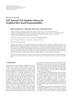
Here, we propose the multiplex-multicast (M-M) scheme
[10] to be used in downlink stream. This proposed modi-
fication exploits the fact that there is an opportunity with
the access point to combine the data from several downlink
streams into a single larger downlink packet. This will reduce
the overhead from that of multiple VoIP packets to that of a
single packet (thereby resulting in better bandwidth utiliza-
tion). This scheme also saves the time period correspond-
ing to SIFS intervals between the two adjacent time slots
(for data to be sent in the downlink direction). The modi-
fied ICF scheme, as shown in Figure 4, saves large amount of
MAC and PHY layer overheads by transmitting a single large
packet rather than multiple smaller packets with their indi-
vidual overheads. As shown by the calculations later in this
section, the time required for sending 3 downlink packets
(and therefore data of three users) in the current ICF scheme
canbeusedtosenddataof8users.Thebandwidththussaved
can be used for supporting additional stations, thereby in-
creasing the capacity.
In the modified scheme, at the start of an ICF cycle, the
uplink stations will send the packets according to the en-
tries in the SV. When all uplink transmission is complete for
the given cycle, the AP will sense that the channel is free for
SIFS time interval and then it will take the control of channel
to transmit the downlink voice traffic. The downlink VoIP
traffic first goes through an MUX in the voice gateway. The
MUX replaces the RTP, UDP, and IP (combined header size
of 40bytes) headers of each voice packet with a compressed
miniheader of 2 bytes, which combines multiple packets into
a single multiplexed packet then multicasts the multiplexed
packet (containing downlink voice traffic as per the entries
in the SV) to the WLAN through the AP using a multicast
IP address. The payload of each VoIP packet is preceded by
a miniheader in which there is an identification ID used to
identify the session of VoIP packet. All STAs will receive the
multicast packets and their packets will be extracted by VoIP
ID present in the miniheader. The extraction is performed by
a DEMUX at the receiver. After retrieving the VoIP payload,
the DEMUX then restores the original RTP header and nec-
essary destination information and assembles the data into
its original form before forwarding it to the VoIP application.
The proposed modification is illustrated in Figure 5.
We now illustrate the saving in bandwidth that can be
achieved using M-M scheme in downlink. The following cal-
culations show that 8 stations can receive their downlink
VoIP packets in three ICF time slots using the MICF scheme
(this takes 8 time slots in the basic ICF scheme). The time
slots made available by using M-M scheme may be utilized to
accommodate a larger number of uplink stations. The polling
queue is maintained using the same algorithm as the one
used in the basic ICF:
ICF time slot
= OH
sender
+OH
hdr
+Payload. (5)
The optimal payload size for the multiplexed downlink
packet is chosen to be 1500 bytes (this choice of packet size
is explained later in the section), and for a voice frame data
size of 160 bytes (corresponding to the G.711 codec), this im-
plies that multiplexing 8 stations results in an optimal packet
size.
The time duration T
down
to send a multiplexed packet
containing 8 voice frames can be obtained as follows [10]:
T
down
= 8/11
∗
payload + 2
∗
N + H
udp
+ H
mac
+OH
sender
,
(6)
where payload
= 160 bytes, H
UDP
= 8bytes,H
UDP
= 20 bytes,
H
MAC
= 34 bytes, and OH
Sender
= SIFS + PHY = 202 mi-
croseconds.
On substituting the values, we obtain T
down
to be about
1200 microseconds. This duration corresponds to about 3
ICF time slot durations (refer to (4)).
Multiplexing more stations will lead to greater saving in
bandwidth, but it will result in an increase in the probability
of packet loss because of increased packet size [15–17], and
thus it will negate the gain achieved. There is tradeoff be-
tween packet size and packet loss rates. The payload size has
been chosen to be 1500 bytes, as this payload size produces
a good compromise between effective throughput and band-
width gain due to larger payload size (refer to [17, Figure 2]).
In our simulation, we have multiplexed the data of 8 VoIP
STAs (to achieve the optimum payload size of 1500 bytes).
We can send more than one multiplexed packet of 1500 bytes
6 EURASIP Journal on Wireless Communications and Networking
S1
S2
Sn
MUX AP
Vo ic e g a te w ay
Multicast
S1 S2 Sn
DEMUX DEMUX DEMUX
IP 1 UDP 1 RTP 1 Payload 1
IP n UDP n RTP n Payload n
Multicast
IP header
UDP
MH
Payload 1
MH
Payload 2 ···
MH
Payload n
MH
mini header
Multiplexed packet structure
UDP 1 RTP 1 Payload 1 UDP n RTP n Payload n
.
.
.
···
MUX/DEMUX procedure
Figure 5: Mux/Demux procedure for MICF.
payload if more time slots are available in the CFP. Any pack-
ets remaining at the end of the CFP period will be dropped
as in the ordinary ICF case.
Implementation of the M-M scheme improves the voice
capacity of the WLAN. However, on the other hand, this
scheme introduces some complexity in form of MUX func-
tionality at gateway and DEMUX functionality at the receiv-
ing station. The receiving stations have to demultiplex the
received multiplexed multicast packet to extract the payload
intended for them. This adds some processing delay; how-
ever, this delay is small and can be offset by choosing better
(and costlier) hardware.
5. SIMULATION RESULTS
This section presents some simulation results to compare the
proposed MICF with the existing schemes. Using the infor-
mation provided in tables and equations in the previous sec-
tions, the call capacity (number of simultaneous voice calls)
for the different schemes has been calculated. Figure 4 shows
a comparison between ICF, basic PCF, and MICF. In this sim-
ulation, the CFP is taken as 15 milliseconds and frame repe-
tition interval as 20 milliseconds. Figure 6 represents loss ra-
tio as a function of the number of simultaneous voice calls.
As it is evident from the plot, the proposed MICF scheme
has the lowest loss ratio for a given number of simultaneous
calls (the region of interest is the one corresponding to loss
ratio of 1% or less). A more important measure of the ef-
ficacy of scheme is the number of simultaneous calls while
maintaining the QoS requirement. Generally, a loss ratio of
Table 3
N
max
(simulated)
PCF ICF MICF
15 ms 6 30 39
17 ms 7 37 46
19 ms 10 42 53
less than 0.01 results in acceptable QoS. For this loss ratio,
MICF can support a larger number of simultaneous calls as
compared to basic ICF. Ta ble 3 lists the call capacities of the
various schemes for different values of CFP interval. Figure 7
shows that by increasing the CFP period, we can improve the
call capacity, but this results in unfair distribution of band-
width between real-time (in CFP) and nonreal-time (in CP)
traffics. The choice of CFP period is therefore a compromise
between call capacity and fair distribution between real-time
and nonreal-time traffics.
The simulation parameters used for the above results are
briefly explained below.
(1) In these simulations, the G.711 codec has been as-
sumed, and this results in corresponding payload size
of 160 bytes (packetization interval of 20 millisec-
onds).
(2) The superframe size is dependent on the packetization
interval of the codec. The G.711 codec, however, does
not constrain the packetization interval. We have cho-
sen 20 milliseconds (which correspond to the pack-
etization interval of a lot of popular codecs) as the
Sanjaya Gupta et al. 7
70605040302010
Numbers of calls
10
−4
10
−3
10
−2
10
−1
10
0
Loss ratio
Loss ratio vesus numbers of stations for MICF, ICF, PCF
MICF
ICF
PCF
Figure 6: Comparison of PCF, ICF, and MICF for CFP = 15 mil-
liseconds.
60555045403530
Numbers of calls
10
−4
10
−3
10
−2
10
−1
10
0
Loss ratio
Loss ratio versus numbers of stations for MICF
CFP
= 15 ms
CFP
= 17 ms
CFP
= 19 ms
Figure 7: Effect of varying CFP period on MICF.
superframe size. In these simulations, CFP interval val-
ues varying from 15 milliseconds to 19 milliseconds
have been used.
(3) Critical values of loss ratio and delay for maintain-
ingQoShavebeenassumedtobe1%[9]and60mil-
liseconds, respectively. Consecutive packet loss has also
been constrained to less than 1% for maintaining QoS.
Some assumptions made during the simulations are as fol-
lows.
(1) Hidden terminal problem is assumed not to be present
(needed in PCF simulations).
(2) All stations are assumed to have PCF mode capability.
(3) Network and stations have been assumed to have ca-
pability to handle multiplexed and multicast packets.
(4) No stations are in power save mode.
(5) The simulation assumes an 802.11b DSSS physical
layer at the bottom of the protocol stack.
(6) Traffic patterns are assumed to be the ones that corre-
spond to the BSS having reached steady state.
6. CONCLUSIONS
This paper proposes a scheme for increasing call capacity
of voice traffic.¡?tex cmt
= ”There is a difference between
the electronic version and manu-script of Figure 5” Please
check.”?¿ The ICF technique which leads to a large call ca-
pacity has been modified to increase the call capacity further.
The proposed MICF scheme improves the performance by
further 30 % (refer to Figure 6, where for loss ratio of 1%,
the number of simultaneous calls for MICF is 39 as opposed
to 30 for ICF; these numbers are also listed in Tab le 3). The
proposed scheme exploits the strength of the M-M scheme
and integrates it into the ICF technique resulting in a high
call capacity procedure.
ACKNOWLEDGMENT
The authors would like to thank Paritosh Mukhija for his
contribution to the simulations.
REFERENCES
[1] IEEE 802.11, IEEE Standards for Information Technology—
Telecommunication and Information Exchange between
Systems—Local and Metropolitan Area Network—Specific
Requirement—Part 11: “Wireless LAN Medium Access Con-
trol (MAC) and Physical Layer (PHY) Specification”, 1999.
[2] P. Gopalakrishnan, D. Famolari, and T. Kodama, “Improving
WLAN voice capacity through dynamic priority access,” in
Proceedings of the IEEE Global Telecommunications Conference
(GLOBECOM ’04), vol. 5, pp. 3245–3249, Dallas, Tex, USA,
November-December 2004.
[3] A. Kopsel and A. Wolisz, “Voice transmission in an IEEE
802.11 WLAN based access network,” in Proceedings of the 4th
ACM International Workshop on Wireless Mobile Multimedia
(WoWMoM ’01), pp. 23–32, Rome, Italy, July 2001.
[4] D. P. Hole and F. A. Tobagi, “Capacity of an IEEE 802.11b wire-
less LAN supporting VoIP,” in Proceedings of the IEEE Inter-
national Conference on Communications (ICC ’04), vol. 1, pp.
196–201, Paris, France, June 2004.
[5] H H. Liu and J L. C. Wu, “A scheme for supporting voice
over IEEE 802.11 wireless local area network,” Proceedings o f
the National Science Council, Republic of China, Part A: Physical
Science and Engineering, vol. 25, no. 4, pp. 259–268, 2001.
[6] L. Zhao and C. Fan, “M-PCF: Modified IEEE 802.11 PCF pro-
tocol implementing QoS,” Electronics Letters, vol. 38, no. 24,
pp. 1611–1613, 2002.
8 EURASIP Journal on Wireless Communications and Networking
[7] P. Brady, “A model for generating on-off speech patterns in
two-way conversation,” Bell System Technical Journal, vol. 48,
no. 7, pp. 2245–2272, 1969.
[8] Y J. Kim and Y J. Suh, “Adaptive polling MAC schemes for
IEEE 802.11 wireless LANs supporting voice-over-IP (VoIP)
services,” Wireless Communications and Mobile Computing,
vol. 4, no. 8, pp. 903–916, 2004.
[9] R. Y. W. Lam, V. C. M. Leung, and H. C. B. Chan, “Polling-
based protocols for packet voice transport over IEEE 802.11
wireless local area networks,” IEEE Wireless Communications,
vol. 13, no. 1, pp. 22–29, 2006.
[10] W. Wang, S. C. Liew, and V. O. K. Li, “Solutions to perfor-
mance problems in VoIP over a 802.11 wireless LAN,” IEEE
Transactions on Vehicular Technology, vol. 54, no. 1, pp. 366–
384, 2005.
[11] T. Kawata, S. Shin, A. G. Forte, and H. Schulzrinne, “Using
dynamic PCF to improve the capacity for VoIP traffic in IEEE
802.11 networks,” in Proceedings of the IEEE Wireless Commu-
nications and Networking Conference (WCNC ’05), vol. 3, pp.
1589–1595, New Orleans, La, USA, March 2005.
[12] HelloSoft’s family of Configurable WLAN licensable IP,
/>[13] VT6655 WLAN Controller, />ducts/networking/wireless/vt6655/.
[14] Ittiam 802.11 MAC, />wlan-mac.htm.
[15] I. Cheng, L. Ying, and A. Basu, “Packet loss modeling for
perceptually optimized 3D transmission,” in Proceedings of
the IEEE International Conference on Multimedia and Expo
(ICME ’06), pp. 1229–1232, Toronto, Ontario, Canada, July
2006.
[16] J. Korhonen and Y. Wang, “Effect of packet size on loss rate
and delay in wireless links,” in Proceedings of the IEEE Wire-
less Communications and Networking Conference (WCNC ’05),
vol. 3, pp. 1608–1613, New Orleans, La, USA, March 2005.
[17] S. Choudhury and J. D. Gibson, “Payload length and rate
adaptation for throughput optimization in wireless LANs,”
in Proceedings of the IEEE Vehicular Technology Conference
(VTC ’06), vol. 5, pp. 2444–2448, Melbourne, VIC, Australia,
May 2006.
[18] J. Davidson and J. Peters, Voice over IP Fundamentals,Cisco
Press, 2nd edition, 2001.
[19]O.Hersent,J P.Petit,andD.Gurle,Beyond VoIP Protocols,
John Wiley & Sons, Hoboken, NJ, USA, 2005.