Báo cáo hóa học: " Research Article A Framework for System-Level Modeling and Simulation of Embedded Systems Architectures" ppt
Bạn đang xem bản rút gọn của tài liệu. Xem và tải ngay bản đầy đủ của tài liệu tại đây (707.68 KB, 11 trang )
Hindawi Publishing Corporation
EURASIP Journal on Embedded Systems
Volume 2007, Article ID 82123, 11 pages
doi:10.1155/2007/82123
Research Article
A Framework for System-Level Modeling and Simulation of
Embedded Systems Architectures
Cagkan Erbas, Andy D. Pimentel, Mark Thompson, and Simon Polstra
Computer Systems Architecture Group, Informatics Institute, Faculty of Science, University of Amsterdam,
Kruislaan 403, SJ Amsterdam, The Netherlands
Received 31 May 2006; Revised 7 December 2006; Accepted 18 June 2007
Recommended by Antonio Nunez
The high complexity of modern embedded systems impels designers of such systems to model and simulate system components
and their interactions in the early design stages. It is therefore essential to develop good tools for exploring a wide range of design
choices at these early stages, where the design space is very large. This paper provides an overview of our system-level modeling and
simulation environment, Sesame, which aims at efficient design space exploration of embedded multimedia system architectures.
Taking Sesame as a basis, we discuss many important key concepts in early systems evaluation, such as Y-chart-based systems
modeling, design space pruning and exploration, trace-driven cosimulation, and model calibration.
Copyright © 2007 Cagkan Erbas et al. This is an open access article distributed under the Creative Commons Attribution License,
which permits unrestricted use, distribution, and reproduction in any medium, provided the original work is properly cited.
1. INTRODUCTION
The e ver increasing complexity of modern embedded sys-
tems has led to the emergence of system-level design [1].
High-level modeling and simulation, which allows for cap-
turing the behavior of system components and their interac-
tions at a high level of abstraction, plays a key role in system-
level desig n. Because high-level models usually require less
modeling effortandexecutefaster,theyareespeciallywell
suited for the early design stages, where the design space is
very large. Early exploration of the design space is critical,
becauseearlydesignchoiceshaveeminenteffect on the suc-
cess of the final product.
The traditional practice for embedded systems perfor-
mance evaluation often combines two types of simulators,
one for simulating the programmable components run-
ning the software and one for the dedicated hardware part.
For simulating the software part, instruction-level or cycle-
accurate simulators are commonly used. The hardware parts
are usually simulated using hardware RTL descriptions re-
alized in VHDL or Verilog. However, using such a hard-
ware/software cosimulation environment during the early
design stages has major drawbacks: (i) it requires too much
effort to build them, (ii) they are often too slow for ex-
haustive explorations, and (iii) they are inflexible in evalu-
ating different hardware/software partitionings. Because an
explicit distinction is made between hardware and software
simulation, a complete new system model might be required
for the assessment of each hardware/software partitioning.
To overcome these shortcomings, a number of high-level
modeling and simulation environments have been proposed
[2–5]. These recent environments break off from low-level
system specifications, and define separate high-level specifi-
cations for behavior (what the system should do) and archi-
tecture (how it does it).
This paper provides an overview of the high-level mod-
eling and simulation methods as employed in embedded
systems design, focusing on our Sesame framework in par-
ticular. The Sesame environment primarily focuses on the
multimedia application domain to efficiently prune and
explore the design space of target platform architectures.
Section 2 introduces the conceptual view of Sesame by dis-
cussing several design issues regarding the modeling and
simulation techniques employed within the framework.
Section 3 summarizes the design space pruning stage which
is performed before cosimulation in Sesame. Section 4 dis-
cusses the cosimulation framework itself from a software
design and implementation point of view. Section 5 ad-
dresses the calibration of system-level simulation models. In
Section 6, we report experimental results achieved using the
Sesame framework. Section 7 discusses related work. Finally,
Section 8 concludes the paper.
2 EURASIP Journal on Embedded Systems
Processor 1 Processor 2
B
C
A
Memory
Application
model
Architecture
model
Bus
FIFO
Event
trace
(a)
Processor 1 Processor 2
B
C
A
Memory
Application
model
Architecture
model
Mapping
layer
Kahn process
network with
C/C++ processes
Objects within
the same
time domain
Bus
FIFO
Event
trace
VP-A VP-B
VP-C
1
2
3
Buffer
(b)
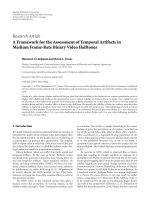
Figure 1: (a) Mapping an application model onto an architecture
model. An event-trace queue dispatches application events from
a Kahn process towards the architecture model component onto
which it is mapped. (b) Sesame’s three-layered structure: applica-
tion model layer, architecture model layer, and the mapping layer
which is an interface between application and architecture models.
2. THE SESAME APPROACH
The Sesame modeling and simulation environment facili-
tates performance analysis of embedded media systems ar-
chitectures according to the Y-chart design principle [6, 7].
This means that Sesame decouples application form archi-
tecture by recognizing two distinct models for them. Accord-
ing to the Y-chart approach, an application model—derived
from a target application domain—describes the functional
behavior of an application in an architecture-independent
manner. The application model is often used to study a tar-
get application and obtain rough estimations of its perfor-
mance needs, for example, to identify computationally ex-
pensive tasks. This model correctly expresses the functional
behavior, but is free from architectural issues, such as tim-
ing characteristics, resource utilization, or bandwidth con-
straints. Next, a platform architecture model—defined with
the application domain in mind—defines architecture re-
sources and captures their performance constraints. Finally,
an explicit mapping step maps an application model onto
an architecture model for cosimulation, after which the sys-
tem performance can be evaluated quantitatively. This is de-
picted in Figure 1(a). The performance results may inspire
the system designer to improve the architecture, modify the
application, or change the projected mapping. Hence, the Y-
chart modeling methodology relies on independent applica-
tion and architecture models in order to promote their reuse
to the greatest conceivable extent.
For application modeling, Sesame uses the Kahn pro-
cess network (KPN) [ 8]modelofcomputationinwhich
parallel processes—implemented in a high-level language—
communicate with each other via unbounded FIFO chan-
nels. Hence, the KPN model unveils the inherent task-level
parallelism available in the application and makes the com-
munication explicit. Furthermore, the code of each Kahn
process is instrumented with annotations describing the ap-
plication’s computational actions, which allows to capture
the computational behavior of an application. The read-
ing from and writing to FIFO channels represent the com-
munication behavior of a process within the application
model. When the Kahn model is executed, each process
records its computational and communication actions, and
thusgeneratesatraceofapplication events. These application
events represent the application tasks to be performed and
are necessary for driv ing an architecture model. Application
events are generally coarse grained, such as read(channel
id,
pixel
block) or execute(DCT).
Parallelizing applications. The KPN applications of
Sesame are obtained by automatically converting a sequen-
tial specification (C/C++) using the KPNgen tool [9]. This
conversion is fast and correct by construction. As input
KPNgen accepts sequential applications specified as static
affine nested loop programs, onto which as a first step it
applies a number of source-level transformations to adjust
the amount of parallelism in the final KPN, the C/C++ code
is transformed into single assigment code (SAC), which re-
sembles the dependence graph (DG) of the original nested
loop program. Hereafter, the SAC is converted to a polyhe-
dral reduced dependency graph (PRDG) data structure, be-
ing a compact representation of a DG in terms of polyhedra.
In the final step, a PRDG is converted into a KPN by associat-
ing a KPN process with each node in the PRDG. The parallel
Kahn processes communicate with each other according to
the data dependencies given in the DG. Further information
on KPN generation can be found in [9, 10].
An architecture model simulates the performance con-
sequences of the computation and communication events
generated by an application model. It solely accounts for
architectural (performance) constraints and does not need
to model functional behavior. This is possible because the
functional behavior is already captured by the application
model, which drives the architecture simulation. The tim-
ing consequences of application events are simulated by
Cagkan Erbas et al. 3
parameterizing each architecture model component with a
table of operation latencies. The table entries could include,
for example, the latency of an execute(DCT) event, or the
latency of a memory access in the case of a memory com-
ponent. This trace-driven cosimulation of application and
architecture models allows to, for example, quickly evaluate
different hardware/software partitionings by just altering the
latency parameters of architecture model components (i.e.,
a low latency refers to a hardware implementation (compu-
tation) or on-chip memory access (communication), while
a high latency models a software implementation or access-
ing an off-chip memory). With respect to communication,
issues such as synchronization and contention on the shared
resources are also captured in the architectural modeling.
To realize trace-driven cosimulation of application and
architecture models, Sesame has an intermediate mapping
layer. This layer consists of virtual processor components,
which are the representation of application processes at the
architecture level, and FIFO buffers for communication be-
tween the virtual processors. As shown in Figure 1(b), there
is a one-to-one relationship between the Kahn processes and
channels in the application model and the virtual proces-
sors and buffers in the mapping layer. The only difference is
that the buffers in the mapping layer are limited in size, and
their size depends on the modeled architecture. The map-
ping layer, in fact, has three functions [2]. First, it controls
the mapping of Kahn processes (i.e., their event traces) onto
architecture model components by dispatching application
events to the correct architecture model component. Second,
it makes sure that no communication deadlocks occur when
multiple Kahn processes are mapped onto a single architec-
ture model component. In this case, the dispatch mecha-
nism also provides various strategies for application event
scheduling. Finally, the mapping layer is c apable of dynami-
cally transforming application events into lower-level archi-
tecture events in order to realize flexible refinement of archi-
tecture models [2, 11].
The output of system simulations in Sesame provides the
designer with performance estimates of the system(s) under
study together with statistical information such as utilization
of architecture model components (id le/busy times), the de-
gree of contention in a system, profiling information (time
spent in different executions), critical path analysis, and av-
erage bandwidth between architecture components. These
high-level simulations allow for early evaluation of different
design choices. Moreover, they can also be useful for identi-
fying trends in the systems’ behavior, and help reveal design
flaws/bottlenecks early in the design cycle.
Despite of being an effective and efficient performance
evaluation technique, high-level simulation would still fail to
explore large parts of the design space. This is because each
system simulation only evaluates a single design point in the
maximal design space of the early design stages. Thus, it is ex-
tremely important that some direction is provided to the de-
signer as a guidance toward promising system architectures.
Analytical methods may be of great help here, as they can
be utilized to identify a small set of promising candidates.
The designer then can focus only on this small set, for which
simulation models can be constructed at multiple levels of
abstraction. The process of trimming down an exponential
design space to some finite set is called design space pruning.
In the next section, we briefly discuss how Sesame prunes the
design space by making use of analytical modeling and mul-
tiobjective evolutionary algorithms [12].
3. DESIGN SPACE PRUNING
As already mentioned in the previous section, Sesame sup-
ports separate application and architecture models within its
exploration framework. This separation implies an explicit
mapping step for cosimulation of the two models. Since the
enumeration of all possible mappings grows exponentially, a
designer usually needs a subset of best candidate mappings
for further evaluation in terms of cosimulation. Therefore,
in summary, the mapping problem in Sesame is the optimal
mapping of an application model onto a (platform ) architec-
ture model. The problem formulation in Sesame takes three
objectives into account [12]: maximum processing time in
the system, total power consumption of the system, and
the cost of the architecture. This section aims at giving an
overview of the formulation of the mapping problem which
allows us to quickly search for promising candidate system
architectures with respect to the above three objectives.
Application modeling
The application models in Sesame are process networks
which can be represented by a graph AP
= (V
K
, E
K
), where
the sets V
K
and E
K
refer to the nodes (i.e., processes) and the
directed channels between these nodes, respectively. For each
node in the application model, a computation requirement
(workload imposed by the node onto a particular compo-
nent in the architecture model), and an allele set (the proces-
sors that it can be mapped onto) are defined. For each chan-
nel in the application model, a communication requirement
is defined only if that channel is mapped onto an external
memory element. Hence, we neglect internal communica-
tions (within the same processor) and only consider external
(interprocessor) communications.
Architecture modeling
The architecture models in Sesame can also be represented by
agraphAR
= (V
A
, E
A
), where the sets V
A
and E
A
denote the
architecture components and the connections between them,
respectively. For each processor in an architecture model, we
define the parameters processing capacity, power consump-
tion during execution, and a fixed cost.
Having defined more abstract mathematical models for
Sesame’s application and architecture model components,
we have the following optimization problem.
Definition 1 (MMPN problem [12, 13]). Multiprocessor
mappings of process networks (MMPN) problem is
min f(x)
=
f
1
(x), f
2
(x), f
3
(x)
subject to g
i
(x), i ∈{1, , n}, x ∈ X
f
,
(1)
4 EURASIP Journal on Embedded Systems
where f
1
is the maximum processing time, f
2
is the total
power consumption, f
3
is the total cost of the system.
The functions g
i
are the constraints, and x ∈ X
f
are the
decision variables. These variables represent decisions like
which processes are mapped onto which processors, or which
processors are used in a particular architecture instance. The
constraints of the problem make sure that the decision vari-
ables are valid, that is, X
f
is the feasible set. For example, all
processes need to be mapped onto a processor from their al-
lele sets; or if two communicating processes are mapped onto
the same processor, the channel(s) between them must also
be mapped onto the same processor, and so on. The opti-
mization goal is to identify a set of solutions which are supe-
rior to all other solutions when all three objective functions
are minimized.
Here,wehaveprovidedanoverviewoftheMMPNprob-
lem. The exact mathematical modeling and formulation can
be found in [12].
3.1. Multiobjective optimization
To solve the above multiobjective integer optimization prob-
lem, we use the (improved) strength Pareto evolutionary
algorithm (SPEA2) [14] that finds a set of approximated
Pareto-optimal mapping solutions, that is, solutions that are
not dominated in terms of quality (performance, power, and
cost) by any other solution in the feasible set. To this end,
SPEA2 maintains an external set to preserve the nondomi-
nated solutions encountered so far besides the original popu-
lation. Each mapping solution is represented by an individual
encoding, that is, a chromosome in which the genes encode
the values of parameters. S PEA2 uses the concept of domi-
nance to assign fitness values to individuals. It does so by tak-
ing into account how many individuals a solution dominates
and is dominated by. Distinct fit ness assignment schemes are
defined for the population and the external set to always en-
sure that better fitness values are assigned to individuals in
the external set. Additionally, SPEA2 performs clustering to
limit the number of individuals in the external set (without
losing the boundary solutions) while also maintaining diver-
sity among them. For selection, it uses binary tournament
with replacement. Finally, only the external nondominated
set takes part in selection. In our SPEA2 implementation, we
have also introduced a repair mechanism [12] to handle in-
feasible solutions. The repair takes place before the individu-
als enter evaluation to make sure that only valid individuals
are e valuated.
In [12], we have shown that an SPEA2 implementation to
heuristically solve the multiobjective optimization problem
can provide the designer with good insight on the quality
of candidate system architectures. This knowledge can sub-
sequently be used to select an initial (platform) architecture
to start the system-level simulation phase, or to guide a de-
signer in finding for example alternative architectures when
system-level simulation indicates that the architecture under
investigation does not fulfill the requirements. Next, we con-
tinue discussing implementation details regarding Sesame’s
system-level simulation fr a mework.
Pearl
VP-A
VP-B
Mapping layer
Architecture model
YX
Z
B
A
Application model
YML
Mapping
A
=> X
B
=> Y
YML editor
Trace A P I
Trace A P I
PNRunner
Figure 2: Sesame software overview. Sesames model description
language YML is used to describe the application model, the archi-
tecture model, and the mapping which relates the two models for
cosimulation.
4. THE COSIMULATION ENVIRONMENT
All three layers in Sesame (see Figure 1(b))arecomposedof
components which should be instantiated and connected us-
ing some form of object creation and initialization mech-
anism. An overview of the Sesame software framework is
given in Figure 2, where we use YML (Y-chart modeling
language) to describe the application model, the architec-
ture model, and the mapping w hich relates the two mod-
els for cosimulation. YML, which is an XML-based lan-
guage, describes simulation models as directed graphs. The
core elements of YML are network, node, port, link,and
property. YML files containing only these elements are
called flat YML. T here are two additional elements set and
script which were added to equip YML with scripting sup-
port to simplify the description of complicated models, for
example, a complex interconnect with a large number of
nodes. We now briefly describe these YML elements.
(i) network: network elements contain graphs of nodes
and links, and may also contain subnetworks which create
hierarchy in the model description. A network element re-
quires a name and optionally a class attribute. Names must
be unique in a network for they are used as identifiers.
(ii) node: node elements represent building blocks (or
components) of a simulation model. Kahn processes in an
application model or components in an architecture model
are represented by nodes in their respective YML descrip-
tion files. Node elements also require a name and usually a
class attribute which are used by the simulators to identify
the node type. For example, in Figure 3(a), the class attribute
of node A specifies that it is a C++ (application) process.
(iii) port: port elements add connection points to nodes
and networks. They require name and dir attributes. The
dir attribute defines the direction of the port and may have
values in or out. Port names must also be unique in a node or
network.
Cagkan Erbas et al. 5
<network name="ProcessNetwork" class="KPN">
<property name="library" value="libPN.so"/>
<node name="A" class="CPP
Process">
<port name="port0" dir="in"/>
<port name="port1" dir="out"/>
</node>
<node name="B" class="CPP
Process">
<port name="port0" dir="in"/>
<port name="port1" dir="out"/>
</node>
<node name="C" class="CPP
Process">
<port name="port0" dir="in"/>
<port name="port1" dir="out"/>
</node>
<link innode="B" inport="port1"
outnode="A" outport="port0"/>
<link innode="A" inport="port1"
outnode="C" outport="port0"/>
<link innode="C" inport="port1"
outnode="B" outport="port0"/>
</network>
(a) YML description of process network in Figure 1
<set init="$i = 0" cond="$i < 10" loop="$i++">
<script>
$nodename="processor$i"
<script/>
<node name="$nodename" class="pearl
object">
<port name="port0" dir="in"/>
<port name="port1" dir="out"/>
</node>
</set>
(b) An example illustrating the usage of set and script elements
<mapping side="source" name="application">
<mapping side="dest" name="architecture">
<map source="A" dest="X">
<port source="portA" dest="portBus"/>
</map>
<map source="B" dest="Y">
<port source="portB" dest="portBus"/>
</map>
<instruction source="op
A" dest="op A"/>
<instruction source="op
B" dest="op B"/>
</mapping>
</mapping>
(c) The YML for the mapping in Figure 2
Figure 3: Structure and mapping descriptions via YML files.
(iv) link: link elements connect ports. They require
innode, inport, outnode,andoutport attributes. The
innode and outnode attributes denote the names of nodes
(or subnetworks) to be connected. Ports used for the connec-
tion are specified by inport and outport.
(v) property: property elements provide additional
information for YML objects. Certain simulators may re-
quire certain information on parameter values. For exam-
ple, Sesame ’s architecture simulator needs to read an array
of execution latencies for each processor component in order
6 EURASIP Journal on Embedded Systems
to associate timing values to incoming application events. In
Figure 3(a), the ProcessNetwork element has a library prop-
erty which specifies the name of the shared library where the
object code belonging to ProcessNetwork,forexample,object
codes of its node elements A, B,andC reside. Property ele-
ments require name and value attributes.
(vi) script: the script element supports Perl as a script-
ing language for YML. The text encapsulated by the script
element is processed by the Perl interpreter in the order it ap-
pears in the YML file. The script element has no attributes.
Thenamingsinname, class,andvalue attributes that be-
gin with a “$” are evaluated as global Perl variables within
the current context of the Perl interpreter. Therefore, users
should take good care to avoid name conflicts. The script el-
ement is usually used together with the set element in order
to create complex network structures. Figure 3(b) gives such
an example, which will be explained below.
(vii) set: the set element provides a for-loop like struc-
ture to define YML structures which simplifies complex net-
work descriptions. It requires three attributes init, cond,
and loop. YML interprets the values of these attributes as
a script element. The init is evaluated once at the begin-
ning of set element processing, cond is evaluated at the be-
ginning of every iteration and is considered as a boolean. The
processing of a set element stops when its cond is false or 0.
The loop attribute is evaluated at the end of each iteration.
Figure 3(b) provides a simple example in which the set ele-
ment is used to generate ten processor components.
The YML description of the process network in
Figure 1(a) is shown in Figure 3. The process network de-
fined has three C++ processes, each associated with input
and output ports, which are connected through the link ele-
ments and embedded in ProcessNetwork. In addition to struc-
tural descriptions, YML is also used to specify mapping de-
scriptions, that is, relating application tasks to architecture
model components.
(i) mapping: mapping elements identify application and
architecture simulators for mapping. An example is given
with the following map element.
(ii) map: map elements map application nodes (model
components) onto architecture nodes. The node mapping in
Figure 2, that is mapping processes A and B onto processors
X and Y, is given in Figure 3(c) where source (dest)refersto
the application (architecture) side.
(iii) port: port elements relate application ports to
architecture ports. When an application node is mapped
onto an architecture node, the connection p oints (or ports)
also need to be mapped to specify which communication
medium should be used in the architecture model simulator.
(iv) instruction: instruction elements specify compu-
tation and communication events generated by the applica-
tion simulator and consumed by the architecture simulator.
In short, they map application event names onto architecture
event names.
Sesame ’s application simulator is called
PNRunner ,or
process network runner. PNRunner implements the seman-
tics of Kahn process networks and supports the well-known
YAPI interface [15]. It reads a YML application descrip-
tion file and executes the application model described there.
The object code of each process is fetched from a shared
library as specified in the YML description, for example,
“libPN.so” in Figure 3. PNRunner currently supports C++
processes, while any language for which a process loader class
is written could be used. This is because PNRunner relies
on the loader classes for process executions. Besides, from
the perspective of PNRunner , data communicated through
the channels is typed as “blocks of bytes.” Interpretation of
data types is done by processes a nd process loaders. As al-
ready shown in Figure 3, the class attribute of a node in-
forms PNRunner which process loader it should use. To pass
arguments to the process constructors or to the processes
themselves, the property arg has been added to YML. Process
classes are loaded through generated stub code. In Figure 4,
we present a n example application process, which is an IDCT
process from an H.263 decoder application. It is derived from
the parent class Process which provides a common interface.
Following YAPI, ports are template classes to set the type of
data exchanged.
As can be seen in Figure 2, PNRunner also provides a
trace API to drive an architecture simulator. Using this API,
PNRunner c an send application events to the architecture
simulator where their performance consequences are simu-
lated. While reading data from or writing data to ports, PN-
Runner generates a communication event as a side effect.
Hence, communication events are automatically generated.
Computation e vents, however, must be signaled explicitly
by the processes. This is achieved by annotating the process
code with execute(char
∗
) statements. In the main function
of the IDCT process in Figure 4, we show a typical exam-
ple. This process first reads a block of data from port block-
InP, performs an IDCT operation on the data, and writes
output data to port blockOutP.Theread and write func-
tions, as a side effect, automatically generate the commu-
nication events. However, we have added the function call
execute(“IDCT”) to record that an IDCT operation is per-
formed. The string passed to the execute function represents
the type of the execution event and needs to match to the
operations defined in the YML file.
Sesame ’s architecture models are implemented in the
Pearl discrete event simulation language [16], or in SCPEx
[17], which is a variant of Pearl implemented on top of Sys-
temC. Pearl is a small but powerful object-based language
which provides easy construction of abstract architecture
models and fast simulation. It has a C-like syntax with a few
additional primitives for simulation purposes. A Pearl pro-
gram is a collection of concurrent objects which communi-
cate w ith each other through message passing. Each object
has its own data space which cannot be directly accessed by
other objects. The objects send messages to other objects to
communicate, for example, to request some data or opera-
tion. The called object may then perform the request, and if
expected, may also reply to the cal ling object.
The Pearl programming paradigm (as well as that of
SCPEx) differs from the popular SystemC language in a num-
ber of important aspects. Pearl, implementing the message-
passing mechanism, abstracts away the concept of ports and
Cagkan Erbas et al. 7
class Idct: public Process {
InPort<Block> blockInP;
OutPort<Block> blockOutP;
// private member function
void idct (short block);
public:
Idct(const class Id& n, In<Block>& blockinF,
Out<Block>& blockOutF);
const char type() const {return "Idct";}
void main();
};
// constructor
Idct::Idct(const class Id& n, In<Block>& blockInF,
Out<Block>& blockOutF)
: Process(n), blockInP(id("blockInP"), blockInF),
blockOutP(id("blockOutP"), blockOutF)
{}
// main member function
void Idct::main() {
Block tmpblock;
while(true) {
read(blockInP, tmpblock);
idct(tmpblock.data);
execute("IDCT");
write(blockOutP, tmpblock);
}
}
Figure 4: C++ code for the IDCT process taken from an H.263 decoder process network application. The process reads a block of data from
its input port, performs an IDCT operation on the data, and writes the transformed data to its output port.
explicit channels connecting ports as employed in SystemC.
Buffering of messages in the object message queues is also
handled implicitly by the Pearl run-time system, whereas
in SystemC one has to implement explicit buffering. Addi-
tionally, Pearl’s message-passing primitives lucidly incorpo-
rate interobject synchronization, while separate event noti-
fications are needed in SystemC. As a consequence of these
abstractions, Pearl is, with respect to SystemC, less prone to
programming errors [17].
Figure 5 shows a piece of Pearl code implementing a
high-level processor component. Pearl objects communi-
cate via synchronous or asynchronous messages. The load
method of the processor object in Figure 5 communicates
with the memory object synchronously via the message call:
mem ! load (nbytes, address);
An object sending a synchronous message blocks un-
til the receiver replies with the reply() primitive. Asyn-
chronous messages, however, do not cause the sending ob-
ject to block; the object continues execution with the next
instruction. Pearl objects have message queues where all re-
ceived messages are collected. Objects can wait for messages
to arrive using block() with the method names as parame-
ter or any to refer to all methods. To wait for a certain in-
terval in simulation time, the blockt(interval) primi-
tive is used. In Figure 5, for example, the compute method
models an execution latency with the blockt using the ar-
ray of operation latencies provided by the YML descrip-
tion. So, dependent on the type of the incoming computa-
tion event, a certain latency is modeled. At the end of sim-
ulation, the Pearl runtime system outputs a post-mor tem
analysis of the simulation results. For this purpose, it keeps
track of some statistical information such as utilization of ob-
jects (idle/busy times), contention (busy objects with pend-
ing messages), profiling (time spent in object methods),
critical path analysis, and average bandwidth between ob-
jects.
5. CALIBRATING SYSTEM-LEVEL MODELS
As was explained, an architecture model component in
Sesame associates latency values to the incoming applica-
tion events that comprise the computation and communi-
cation operations to be simulated. This is accomplished by
parameterizing each architecture model component with a
table of operation latencies. Therefore, regarding the accu-
racy of system-level performance evaluation, it is important
that these latencies correctly reflect the speed of their corre-
sponding architecture components. We now briefly discuss
two techniques (one for software and another one for hard-
ware implementations) which are deployed in Sesame to at-
tain latencies with good accuracy.
8 EURASIP Journal on Embedded Systems
class processor
mem : memory
nopers : integer // needed for array size
opers
t = [nopers] integer // type definition
opers : opers
t // array of operation latencies
simtime : integer // local variable
compute : (operindx:integer)
− > void {
simtime = opers[operindx]; // simulation time
blockt(simtime); // simulate the operation
reply();
}
load : (nbytes:integer, address:integer)
− > void {
mem ! load(nbytes, address); // memory call
reply();
}
// store method omitted
{
while(true) {
block(any);
}
}
Figure 5: Pearl implementation of a generic high-level processor.
PNRunner
C
AC”
BD C’
C’
IPC
ISS
Cross
compiler
(a) Solution for software implementations
PNRunner
Microprocessor
Source code
transformation
Synthesizable
VHDL code
FPGA
a
b
cC
AC’
DB
(b) Solution for hardware implementations
Figure 6: Obtaining low-level numbers for model calibration.
The first technique can be used to calibrate the laten-
cies of programmable components in the architecture model,
such as microprocessors, DSPs, application specific instruc-
tion processors (ASIPs), and so on. The calibration tech-
nique, as depicted in Figure 6(a), requires that the designer
has access to the C/C++ cross compiler and a low-level
(ISS/RTL) simulator of the target processor. In the figure, we
have chosen to calibrate the latency value(s) of (Kahn) pro-
cess C which is mapped to some kind of processor for which
we have a cross compiler and an instruction set simulator
(ISS). First, we take process C, and substitute its Kahn com-
munication for UNIX IPC-based communication (i.e., to re-
alize the interprocess communication between the two sim-
ulators: PNRunner and the ISS), and generate binary code
using the cross compiler. The code of process C in PNRun-
ner is also modified (now called process C”). Process C”
now simply forwards its input data to the ISS, blocks un-
til it receives processed data from the ISS, and then writes
received data to its output Kahn channels. Hence, process
C” leaves all computations to the ISS, which additionally
records the number of cycles taken for the computations
while performing them. Once this mixed-level simulation
is finished, recordings of the ISS can be analyzed statisti-
cally, for example, the arithmetic means of the measured
code fragments can be taken as the latency for the cor-
responding architecture component in the system-level ar-
chitecture model. This scheme can also be easily extended
to an application/architecture mixed-level cosimulation us-
ing a recently proposed technique called trace calibration
[18].
Cagkan Erbas et al. 9
Table 1: Simulation and validation results.
Case study Simulation efficiency Accuracy
Motion-JPEG [2]
(nonrefined)
700 000 cycles/s on
2.8 GHz Pentium 4
—
Motion-JPEG [2]
(refined)
250 000 cycles/s on
2.8 GHz Pentium 4
—
QR Algorithm [21]
5000 cycles/s on
333 MHz Sun Ultra 10
3.5% (best)
36% (worst)
Motion-JPEG [22]
(refined)
1 350 000 cycles/s on
2.8 GHz Pentium 4
0.5% (best)
1.9% (worst)
The second calibration technique makes use of reconfig-
urable computing with field programmable gate arrays (FP-
GAs). Figure 6(b) illustrates this calibration technique for
hardware components. This time it is assumed that the pro-
cess C is to be implemented in hardware. First, the appli-
cation programmer takes the source code of process C and
performs source code transformations on it, which unveils
the parallelism within the process C. These transformations,
starting from a single process, create a functionally equiv-
alent (Kahn) process network with processes at finer gran-
ularities. The abstrac tion level of the processes is lowered
such that a one-to-one mapping of the process network to
an FPGA platform becomes possible. There are already some
prototype environments which can accomplish these steps
for certain applications. For example, the Compaan tool [19]
can automatically perform process network transformations
while the Laura [20] tool can generate VHDL code from a
process network specification. This VHDL code can then be
synthesized and mapped onto an FPGA using commercial
synthesis tools. By mapping process C onto an FPGA and ex-
ecuting the remaining processes of the original process net-
work on a microprocessor (e.g., an FPGA board connected to
a computer using a PCI bus, or a processor core embedded
into the FPGA), statistics on the hardware implementation
of process C can be collected to calibrate the corresponding
system-level hardware component.
6. EXPERIMENTS
In Tabl e 1, we present some numbers of interest from our
earlier experiments with the Sesame framework. The first
two rows correspond to two system-level simulations, where
we have subsequently mapped a Motion-JPEG encoder onto
an MP-SoC platform architecture [2]. In both simulations,
we have encoded 11 picture frames each with a resolution of
352
× 288 pixels and used nonrefined (black-box) processor
components except the DCT processor. The only difference
in two simulations is that the DCT processor is nonrefined
in the first simulation, while a refined pipelined model is
used on the second case. These simulation results reveal that
system-level simulation can be very fast, simulating the entire
multiprocessor system within a ra nge of hundreds of thou-
sands to a few millions of cycles/s, even in the case of model
refinements. The last two rows of Table 1 are on the accuracy
of system-level simulation based on some earlier validation
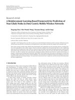
Number of processors
Cycle numbers
Number of MicroBlaze cores
1
2
3
4
4
3
2
1
0
Crossbar platform
0
1
2
3
4
5
×10
8
Figure 7: Performance results of the best mappings obtained by ex-
haustive search.
experiments. These results have been obtained by calibrating
Sesame using techniques from Section 5 and comparing the
results with real implementations on an FPGA. The results
suggest that well-calibrated system-level models can be very
accurate. We should further note that the architecture mod-
els in QR and M-JPEG experiments are only composed of
around 400 and 600 lines of Pearl code, respectively.
Figure 7 shows the results from an experiment in which
we have mapped a restructured version of the afore-
mentioned M-JPEG encoder—containing six application
processes—onto an M P-SoC platform architecture. This ar-
chitecture consists of up to four processor cores connected
by a crossbar sw itch. The processor cores can be of the type
MicroBlaze or PowerPC. This is due to the fact that we are
currently using a Virtex II Pro FPGA platform to validate our
simulation results against a real system prototype. Thanks to
Sesame’s fast architecture simulator, we were able to deter-
mine the performance consequences of all points in a part
of the design space by exhaustively simulating every single
point. This means that we have varied the number of proces-
sors from one to four, the type of processors from MicroBlaze
to PowerPC, and the mappings of the six application pro-
cesses onto these different instances of the platform architec-
ture. All of this yields 10 148 experiments which in total took
86 minutes using the Sesame system-level simulation frame-
work. In Figure 7, we have plotted the performance of the
design points with the best mappings of the application onto
the fourteen different instances of the platform architecture.
We observe that the estimated execution time of the system
ranges from 124, 287, 479 cycles for the fastest implementa-
tion to 457, 546, 152 cycles for the slowest to process an input
of 8 consecutive frames of 128
× 128 pixels in YUV format.
For bigger systems where it is infeasible to explore every point
10 EURASIP Journal on Embedded Systems
in the design space, as explained in Section 3,Sesamerelies
on the outcome of a design space pruning stage, which pre-
cedes the system-level simulation stage and provides input
to the this stage by identifying a set of high-potential design
points that may yield good per formance.
7. RELATED WORK
There are a number of architectural exploration environ-
ments, such as (Metro)Polis [4, 6], Mescal [23], MESH [5],
Milan [24], and various SystemC-based environments like in
[25], that facilitate flexible system-level performance evalua-
tion by providing support for mapping a behavioral applica-
tion specification to an architecture specification. For exam-
ple, in MESH [5], a high-level simulation technique based
on frequency interleaving is used to map logical events (re-
ferring to application functionality) to physical events (refer-
ring to hardware resources). In [26], an excellent survey is
presented of var ious methods, tools, and environments for
early design space exploration. In comparison to most re-
lated efforts, Sesame tries to push the separation of mod-
eling application behavior and modeling architectural con-
straints at the system level to even greater extents. This is
achieved by architecture-independent application models,
application-independent architecture models, and a map-
ping step that relates these models for trace-driven cosim-
ulation.
In [27] Lahiri et al. also use a trace-driven approach, but
this is done to extract communication behavior for study-
ing on-chip communication architectures. Rather than us-
ing the traces as input to an a rchitecture simulator, their
traces are analyzed statically. In addition, a tra ditional hard-
ware/software cosimulation stage is required in order to
generate the traces. Archer [28] shows similarities with the
Sesame framework due to the fact that both Sesame and
Archer stem from the earlier Spade project [29]. A ma-
jor difference is, however, that Archer follows a different
application-to-architecture mapping approach. Instead of
using event traces, it maps the so-called symbolic programs,
which are derived from the application model, onto architec-
ture model resources. Moreover, unlike Sesame, Archer does
not include support for rapidly pruning the design space.
8. DISCUSSION
This paper provided an overview of our system-level model-
ing and simulation environment—Sesame. Taking Sesame as
a basis, we have discussed many important key concepts such
as Y-chart-based systems modeling, design space pruning
and exploration, trace-driven cosimulation, model c alibra-
tion and so on. Future work on Sesame will include (i) ex-
tending application and architecture model libraries further
with components operating at multiple levels of abstraction,
(ii) improving its accuracy with techniques such as trace cal-
ibration [18], (iii) performing further validation case studies
to test proposed accuracy improvements, and (iv) applying
Sesame to other application domains.
What is more, the calibration of timing parameters of the
system-level models by getting feedback from (or coupling
with) low-level simulators or from FPGA prototype imple-
mentations can also be extended to calibrate power numbers.
For example, instead of coupling Sesame with simplescalar to
measure timing values for software components, one could
as well couple Sesame with a low-level power simulator such
as Wattch [30] or Simplepower [31]toobtainpowernum-
bers. The same is true for the hardware components. Once
an FPGA prototype implementation is built, it can be used
for power measurement during execution.
REFERENCES
[1] K. Keutzer, A. R. Newton, J. M. Rabaey, and A. Sangiovanni-
Vincentelli, “System-level design: orthogonalization of con-
cerns and platform-based design,” IEEE Transactions on
Computer-Aided Design of Integrated Circuits and Systems,
vol. 19, no. 12, pp. 1523–1543, 2000.
[2] A. D. Pimentel, C. Erbas, and S. Polstra, “A systematic ap-
proach to exploring embedded system architectures at mul-
tiple abstraction levels,” IEEE Transactions on Computers,
vol. 55, no. 2, pp. 99–112, 2006.
[3] A. Bakshi, V. Prasanna, and A. Ledeczi, “Milan: a model based
integrated simulation framework for design of embedded sys-
tems,” in Proceedings of the Workshop on Languages, Compilers,
and Tools for Embedded Systems (LCTES ’01), pp. 82–87, Snow-
bird, Utah, USA, June 2001.
[4]F.Balarin,Y.Watanabe,H.Hsieh,L.Lavagno,C.Passerone,
and A. Sangiovanni-Vincentelli, “Metropolis: an integrated
electronic system design environment,” Computer, vol. 36,
no. 4, pp. 45–52, 2003.
[5] A. Cassidy, J. Paul, and D. Thomas, “Layered, multi-threaded,
high-level performance design,” in Proceedings of the Interna-
tional Conference on Design, Automation and Test in Europe
(DATE ’03), pp. 954–959, Munich, Germany, March 2003.
[6] F. Balarin, P. D. Giusto, A. Jurecska, et al., Hardware-Software
Co-Design of Embedded Systems: The POLIS Approach,Kluwer
Academic, Boston, Mass, USA, 1997.
[7] B. Kienhuis, E. Deprettere, K. Vissers, and P. van der Wolf,
“An approach for quantitative analysis of application-specific
dataflow architectures,” in Proceedings of IEEE Internat ional
Conference on Application-Specific Systems, Architectures and
Processors (ASAP ’97), pp. 338–349, Zurich, Switzerland, July
1997.
[8] G. Kahn, “The semantics of a simple language for parallel pro-
gramming,” in Proceedings of the IFIP Congress on Information
Processing, pp. 471–475, Stockholm, Sweden, August 1974.
[9] S. Verdoolaege, H. Nikolov, and T. Stefanov, “Improved
derivation of process networks,” in Proceedings of the 4th In-
ternational Workshop on Optimization for DSP and Embedded
Systems (ODES ’06), New York, NY, USA, March 2006.
[10] T. Stefanov, B. Kienhuis, and E. Deprettere, “Algorithmic
transformation techniques for efficient exploration of al-
ternative application instances,” in Proceedings of the 10th
International Symposium on Hardware/Software Codesign
(CODES ’02), pp. 7–12, Estes Park, Colo, USA, May 2002.
[11] C. Erbas and A. D. Pimentel, “Utilizing synthesis methods in
accurate system-level exploration of heterogeneous embedded
systems,” in Proceedings of IEEE Workshop on Signal Processing
Systems (SIPS ’03), pp. 310–315, Seoul, Korea, August 2003.
Cagkan Erbas et al. 11
[12] C. Erbas, S. Cerav-Erbas, and A. D. Pimentel, “Multiobjective
optimization and evolutionary algorithms for the application
mapping problem in multiprocessor system-on-chip design,”
IEEE Transactions on Evolutionary Computation,vol.10,no.3,
pp. 358–374, 2006.
[13] C. Erbas, S. Cerav-Erbas, and A. D. Pimentel, “A multiobjec-
tive optimization model for exploring multiprocessor map-
pings of process networks,” in Proceedings of the 1st IEEE/
ACM/IFIP International Conference on Hardware/Software
Codesign and System Syn thesis, pp. 182–187, Newport Beach,
Calif, USA, October 2003.
[14] E. Zitzler, M. Laumanns, and L. Thiele, “SPEA2: improving
the strength pareto evolutionary algorithm for multiobjective
optimization,” in Evolutionary Methods for Design, Optimisa-
tion and Control with Application to Industrial Problems,K.
Giannakoglou, D. Tsahalis, J. Periaux, K. D. Papailiou, and T.
Fogarty, Eds., pp. 95–100, International Center for Numerical
Methods in Engineering, Barcelona, Spain, 2002.
[15] E. A. de Kock, G. Essink, W. Smits, et al., “YAPI: application
modeling for signal processing systems,” in Proceedings of the
37th Design Automation Conference (DAC ’00), pp. 402–405,
Los Angeles, Calif, USA, June 2000.
[16] J. E. Coffland and A. D. Pimentel, “A software framework
for efficient system-level performance evaluation of embed-
ded systems,” in Proceedings of the ACM Symposium on Applied
Computing, pp. 666–671, Melbourne, Fla, USA, March 2003.
[17] M. Thompson and A. D. Pimentel, “A high-level programming
paradigm for systemC,” in Proceedings of the 4th International
Workshops on Systems, Architectures, Modeling, and Simulation
(SAMOS ’04), vol. 3133 of Lecture Notes in Computer Science,
pp. 530–539, Springer, Samos, Greece, July 2004.
[18]M.Thompson,A.D.Pimentel,S.Polstra,andC.Erbas,
“A mixed-level co-simulation method for system-level de-
sign space explor ation,” in Proceedings of the IEEE/ACM/IFIP
Workshop on Embedded Systems for Real Time Multimedia,pp.
27–32, Seoul, Korea, October 2006.
[19] B. Kienhuis, E. Rijpkema, and E. Deprettere, “Compaan: de-
riving process networks from Matlab for embedded signal
processing architectures,” in Proceedings of the 18th Interna-
tional Workshop Hardware/Software Codesign (CODES ’00),
pp. 13–17, San Diego, Calif, USA, May 2000.
[20] C. Zissulescu, T. Stefanov, B. Kienhuis, and E. Deprettere,
“Laura: leiden architecture research and exploration tool,”
in Proceedings of the 13th International Conference on Field-
Programmable Logic and Applications (FPL ’03), P. Cheung,
G. Constantinides, and J. de Sousa, Eds., vol. 2778 of Lecture
Notes in Computer Science, pp. 911–920, Springer, Lisbon, Por-
tugal, September 2003.
[21]A.D.Pimentel,F.Terpstra,S.Polstra,andJ.E.Coffland,
“On the modeling of intra-task parallelism in task-level paral-
lel embedded systems,” in Domain-Specific Processors: Systems,
Architectures, Modeling, and Simulation, S. Bhattacharyya, E.
Deprettere, and J. Teich, Eds., pp. 85–105, Springer, Berlin,
Germany, 2003.
[22] A. D. Pimentel, “The artemis workbench for system-level
performance evaluation of embedded systems,” International
Journal of Embedded Systems, vol. 1, no. 7, 2005.
[23] A. Mihal, C. Kulkarni, C. Sauer, et al., “Developing architec-
tural platforms: a disciplined approach,” IEEE Design and Test
of Computers, vol. 19, no. 6, pp. 6–16, 2002.
[24] S. Mohanty and V. K. Prasanna, “Rapid system-level perfor-
mance evaluation and optimization for application mapping
onto SoC architectures,” in Proceedings of the 15th Annual IEEE
International ASIC/SOC Conference, pp. 160–167, Rochester,
NY, USA, September 2002.
[25] T. Kogel, A. Wieferin, R. Leupers, et al., “Virtual architecture
mapping: a systemC based methodology for architectural ex-
ploration of system-on-chip designs,” in Proceedings of the 3rd
International Workshop on Computer Systems: Architectures,
Modeling, and Simulation (SAMOS ’03), pp. 138–148, Samos,
Greece, July 2003.
[26] M. Gries, “Methods for evaluating and covering the design
space during early design development,”
Integration, the VLSI
Journal, vol. 38, no. 2, pp. 131–183, 2004.
[27] K. Lahiri, A. Raghunathan, and S. Dey, “System-level perfor-
mance analysis for designing on-chip communication archi-
tectures,” IEEE Transactions on Computer-Aided Design of In-
tegrated Circuits and Systems, vol. 20, no. 6, pp. 768–783, 2001.
[28] V. Zivkovic, E. Deprettere, P. van der Wolf, and E. de
Kock, “Fast and accurate multiprocessor architecture explo-
ration with symbolic programs,” in Proceedings of the Inter-
national Conference on Desig n, Automation and Test in Europe
(DATE ’03), pp. 656–661, Munich, Germany, March 2003.
[29] P. Lieverse, P. van der Wolf, E. Deprettere, and K. Vissers, “A
methodology for architecture exploration of heterogeneous
signal processing systems,” Journal of VLSI Signal Processing
Systems for Signal, Image, and Video Technology, vol. 29, no. 3,
pp. 197–207, 2001.
[30] D. Brooks, V. Tiwari, and M. Martonosi, “Wattch: a framework
for architectural-level power analysis and optimizations,” in
Proceedings of the 27th Annual International Symposium on
Computer Architecture (ISCA ’00), pp. 83–94, Vancouver, BC,
Canada, June 2000.
[31] W. Ye, N. Vijaykrishnan, M. Kandemir, and M. J. Irwin, “The
design and use of simplepower: a cycle-accurate energy es-
timation tool,” in Proceedings of the 37th Design Automation
Conference (DAC ’00), pp. 340–345, Los Angeles, Calif, USA,
June 2000.