Báo cáo hóa học: " Research Article A Shared Memory Module for Asynchronous Arrays of Processors" pot
Bạn đang xem bản rút gọn của tài liệu. Xem và tải ngay bản đầy đủ của tài liệu tại đây (1.91 MB, 13 trang )
Hindawi Publishing Corporation
EURASIP Journal on Embedded Systems
Volume 2007, Article ID 86273, 13 pages
doi:10.1155/2007/86273
Research Article
A Shared Memory Module for Asynchronous
Arrays of Processors
Michael J. Meeuwsen, Zhiyi Yu, and Bevan M. Baas
Department of Electrical and Computer Engineering, University of California, Davis, CA 95616-5294, USA
Received 1 August 2006; Revised 20 December 2006; Accepted 1 March 2007
Recommended by Gang Qu
A shared memory module connecting multiple independently clocked processors is presented. The memory module itself is in-
dependently clocked, supports hardware address generation, mutual exclusion, and multiple addressing modes. The architecture
supports independent address generation and data generation/consumption by different processors which increases efficiency and
simplifies programming for many embedded and DSP tasks. Simultaneous access by different processors is arbitrated using a
least-recently-serviced priority s cheme. Simulations show high throughputs over a variety of memory loads. A standard cell im-
plementation shares an 8 K-word SRAM among four processors, and can support a 64 K-word SRAM with no additional changes.
It cycles at 555 MHz and occupies 1.2 mm
2
in 0.18 µm CMOS.
Copyright © 2007 Michael J. Meeuwsen et al. This is an open access article distributed under the Creative Commons Attribution
License, which permits unrestricted use, distribution, and reproduction in any medium, provided the original work is properly
cited.
1. INTRODUCTION
The memory subsystem is a key element of any compu-
tational machine. The memory retains system state, stores
data for computation, and holds machine instructions for
execution. In many modern systems, memory bandwidth is
the primary limiter of system performance, despite complex
memory hierarchies and hardware driven prefetch mecha-
nisms.
Coping with the intrinsic gap between processor perfor-
mance and memory performance has been a focus of re-
search since the beginning of the study of computer archi-
tecture [1]. The fundamental problem is the infeasibility of
building a memory that is both large and fast. Designers are
forced to reduce the sizes of memories for speed, or pro-
cessors must pay long latencies to access high capacity stor-
age. As memory densities continue to grow, memory perfor-
mance has improved only slightly; processor performance,
on the other hand, has shown exponential improvements
over the years. Processor performance has increased by 55
percent each year, while memory performance increases by
only 7 percent [2]. The primary solution to the memory gap
has been the implementation of multilevel memory hierar-
chies.
In the embedded and signal processing domains, de-
signers may use existing knowledge of system workloads to
optimize the memory system. Typically, these systems have
smaller memory requirements than general purpose com-
puting loads, which makes alternative architectures attrac-
tive.
This work explores the design of a memory subsystem
for a recently introduced class of multiprocessors that are
composed of a large number of synchronous processors
clocked asynchronously with respect to each other. Because
the processors are numerous, they likely have fewer resources
per processor, including instruction and data memory. Each
processor operates independently without a global address
space. To efficiently support applications with large work-
ing sets, processors must be provided with higher capacity
memory storage. The Asynchronous Array of simple Processors
(AsAP) [3] is an example of this class of chip multiprocessors.
To maintain design simplicity, scalability, and compu-
tational density, a traditional memory hierarchy is avoided.
In addition, the low locality in tasks such as those found
in many embedded and DSP applications, makes the cache
solution unattractive for these workloads. Instead, directly-
addressable software-managed memories are explored. T his
allows the programmer to efficiently manage the memory hi-
erarchy explicitly.
The main requirements for the memory system are the
following:
(1) the system must provide high throughput access to
high capacity r andom access memory,
2 EURASIP Journal on Embedded Systems
(2) the memory must be accessible from multiple asyn-
chronous clock domains,
(3) the design must easily scale to support arbitr arily large
memories, and
(4) the impact on processing elements should be mini-
mized.
The remainder of this work is organized as follows. In
Section 2, the current state of the art in memory systems is
reviewed. Section 3 provides an overview of an example pro-
cessor array without shared memories. Section 4 explores the
design space for memory modules. Section 5 descr ibes the
design of a buffered memory module, which has been im-
plemented using a standard cell flow. Section 6 discusses the
performance and power of the design, based on high level
synthesis results and simulation. Finally, the paper concludes
with Section 7.
2. BACKGROUND
2.1. Memory system architectures
Although researchers have not been able to stop the growth
of the processor/memory gap, they have developed a num-
ber of architectural alternatives to increase system perfor-
mance despite the limitations of the available memory. These
solutions range from traditional memory hierarchies to in-
telligent memory systems. Each solution attempts to reduce
the impact of poor memory performance by storing the data
needed for computation in a way that is easily accessible to
the processor.
2.1.1. Traditional memory hierarchies
The primary solution to the processor/memory gap has been
to introduce a local cache memory, exploiting spatial and
temporal locality evident in most software programs. Caches
are small fast memories that provide the processor with a lo-
cal copy of a small portion of main memory. Caches are man-
aged by hardware to ensure that the processor always sees a
consistent view of main memory.
The primary advantage of the traditional cache scheme is
ease of programming. Because caches are managed by hard-
ware, programs address a single large address space. Move-
ment of data from main memory to cache is handled by hard-
ware and is transparent to software.
The primary drawback of the cache solution is its high
overhead. Cache memories typically occupy a significant
portion of chip area and consume considerable power. Cache
memories do not add functionality to the system—all stor-
age provided is redundant, and identical data must be stored
elsewhere in the system, such as in main memory or on disk.
2.1.2. Alternative memory architectures
Scratch Pad Memories are a cache alternative not uncom-
monly found in embedded systems [4]. A scratch-pad mem-
ory is an on-chip SRAM with a similar size and access time as
an L1 (level 1) cache. Scratch pad memories are unlike caches
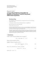
Osc.
(a)
Single
processor
(b)
Figure 1: Block diagram and chip micrograph of the AsAP chip
multiprocessor.
in that they are uniquely mapped to a fixed portion of the
system’s address space. Scratch-pad memory may be used in
parallel with a cache or alone [5]. Banakar et al. report a typ-
ical power savings of 40 percent wh en scratch-pad memories
are used instead of caches [4].
Others have explored alternatives to traditional memory
hierarchies. These include architectures such as Intelligent
RAM (IRAM) [6] and Smart Memories [7].
3. AN EXAMPLE TARGET ARCHITECTURE: AsAP
An example target architecture for this work is a chip mul-
tiprocessor called an Asynchronous Array of simple Proces-
sors (AsAP) [3, 8, 9]. An AsAP system consists of a two-
dimensional array of homogeneous processing elements as
shown in Figure 1. Each element is a simple CPU, which con-
tains its own computation resources and executes its own
locally stored program. Each processing element has a lo-
cal clock source and operates asynchronously with respect to
the rest of the array. The Globally Asynchronous Locally Syn-
chronous (GALS) [10] nature of the array alle viates the need
to distribute a high speed clock across a large chip. The ho-
mogeneity of the processing elements makes the system easy
to scale as additional tiles can be added to the array with little
effort.
Interprocessor communication within the array occurs
through dual-clock FIFOs [11] on processor boundar ies.
These FIFOs provide the required synchronization, as well
as data buffers for rate matching between processors. The in-
terconnection of processors is reconfigurable.
Applications are mapped to AsAP by partitioning com-
putation into many small tasks. Each task is statically mapped
onto a small number of processing elements. For example, an
IEEE 802.11a baseband transmitter has been implemented
on a 22-processor array [9], and a JPEG encoder has been
implemented on a 9-processor array.
AsAP processors are characterized by their very small
memory resources. Small memories minimize power and
area while increasing the computational density of the ar-
ray. No memory hierarchy exists, and memory is managed
entirely by software. Additionally, there is no global address
space, and all interprocessor communication must occur
through the processors’ input FIFOs.
Michael J. Meeuwsen et al. 3
Each processor tile contains memory for 64 32-bit in-
structions and 128 16-bit words. With only 128 words of
randomly-accessible storage in each processor, the AsAP ar-
chitecture is currently limited to applications with small
working sets.
4. DESIGN SPACE EXPLORATION
A wide variety of design possibilities exist for adding larger
amounts of memory to architectures like AsAP. This section
describes the design space and design selection based on es-
timated performance and flexibility.
In exploring the design space, parameters can be catego-
rized into three roughly orthogonal groups.
(1) Physical design parameters,suchasmemorycapacity
and module distribution have little impact on the de-
sign of the memory module itself, but do determine
how the module is integrated into the processing ar-
ray.
(2) Processor interface parameters,suchasclocksource
and buffering have the largest impact on the module
design.
(3) Reconfigurability parameters allow design complexity
to be traded off for additional flexibility.
4.1. Key memory parameters
4.1.1. Capacity
Capacity is the amount of storage included in each mem-
ory module. Memory capacity is driven by application re-
quirements as well as area and performance targets. The
lower bound on memory capacity is given by the memory re-
quirements of targeted applications while die area and mem-
ory performance limit the maximum amount of memory.
Higher capacity RAMs occupy more die area, decreasing the
total computational density of the array. Larger RAMs also
limit the bandwidth of the memory core.
It is desirable to implement the smallest possible memory
required for the targeted applications. These requirements,
however, may not be available at design time. Furthermore,
over-constraining the memory capacity limits the flexibility
of the array as new applications emerge. Hence, the scala-
bility of the memory module design is important, allowing
the memory size to be chosen late in the design cycle and
changed for future designs with little effort.
4.1.2. Density
Memory module density refers to the number of memory
modules integrated into an ar ray of a particular size, and is
determined by the size of the array, available die area, and
application requirements. Typically, the number of memory
modules integrated into an array is determined by the space
available for such modules; however, application level con-
straints may also influence this design parameter. Assuming a
fixed memory capacity per module, additional modules may
be added to meet minimum memory capacity requirements.
Also, some performance increase can be expected by parti-
tioning an application’s data among multiple memory mod-
ules due to the increased memory bandwidth provided by
each module. This approach to increasing performance is not
always practical and does not help if the application does not
saturate the memory interface. It also requires a high degree
of parallelism among data as communication among mem-
ory modules may not be practical.
4.1.3. Distribution
The distribution of memory modules within the array can
take many forms. In general, two topological approaches can
be used. The first approach leaves the processor array in-
tact and adds memory modules in rows or columns as al-
lowed by available area resources. Processors in the array
maintain connectivity to their nearest neighbors, as if the
memory modules were not present. The second approach re-
places processors with memory modules, so that each pro-
cessor neighboring a memory module loses connectivity to
one processor. These strategies are illust rated in Figure 2.
4.1.4. Clock source
Because the targeted arrays are GALS systems, the clock
source for the memory module becomes a key design pa-
rameter. In general, three distinct possibilities exist. First, the
memory module can derive its clock from the clock of a par-
ticular processor. The memory would then be synchronous
with respect to this processor. Second, the memory can gen-
erate its own unique clock. The memory would be asyn-
chronous to all processors in the arr ay. Finally, the memory
could be completely asynchronous, so that no clock would be
required. This solution severely limits the implementation of
the memor y module, as most RAMs provided in standard
cell libraries are synchronous.
4.1.5. Address source
The address source for a memory module has a large impact
on application mapping and performance. To meet the ran-
dom access requirement, processors must be allowed to sup-
ply arbitrary addresses to memory. (1) The obvious solution
uses the processor producing or consuming the memory data
as the address source. The small size of the targeted proces-
sors, however, makes another solution attractive. (2) The ad-
dress and data streams for a memory access can also be par-
titioned among multiple processors. A single processor can
potentially be used to provide memory addresses, while other
processors act as data sources and data sinks. This scheme
provides a potential performance increase for applications
with complex addressing needs because the data processing
and address generation can occur in parallel. (3) A third pos-
sible address source is hardware address generators, which
typically speed up memory accesses significantly, but must
be built into hardware. To avoid unnecessary use of power
and die area, only the most commonly used access patterns
should be included in hardware.
4 EURASIP Journal on Embedded Systems
Memory
Processor
(a)
Memory
Processor
(b)
Memory
Processor
(c)
Figure 2: Various topologies for distr ibution of memories in a processor array. Processor connectivity is maintained when (a) memories are
added to the edge of the array, or (b) the array is split to make room for a row of memories. Processor connectivity is lost when (c) processor
tiles are replaced by memory tiles.
4.1.6. Buffering
The implementation of buffers for accesses to the memory
module provides another design parameter. Buffers may be
used between a processor and a memory module for latency
hiding, synchronization, or rate matching. Without some
level of buffering, processors are tightly coupled to the mem-
ory interface, and prefetching of data is difficult.
4.1.7. Sharing
The potentially large number of processors in a processing
array makes the sharing of memories among processors at-
tractive. In this context, shared m emory serves two distinct
purposes. First, as in more traditional computing, shared
memory can serve as a communication medium among si-
multaneous program threads. Also, in our context, sharing a
memory among multiple processors can enable higher uti-
lization of available memory bandwidth in cases where a sin-
gle thread is unable to saturate the memory bus. In either
case, synchronization mechanisms are required to guarantee
mutual exclusion when memory is shared.
4.1.8. Inter-parameter dependencies
There are strong dependencies among the four parameters
described in the preceding four subsections (clock source,
address source, buffering, and sharing). Selecting a value
for one of the parameters limits the feasible values of the
other parameters. This results in the existence of two distinct
archetype designs for the processor interface. Other design
options tend to be hybrids of these two models and often
have features that limit usefulness.
Type I: bufferless memory
The first design can be derived by forcing a bufferless imple-
mentation. Without buffers, there is no way to synchronize
across clock boundaries, so the memory module must be
synchronous to the interfacing processor. Because processors
are asynchronous to one another, sharing the memory is no
longer feasible, and using an alternate processor as an ad-
dress source is not possible. The resulting design is a mem-
ory module that couples tightly to a single processor. Because
there is no buffering, memory accesses are either tightly in-
tegrated into the processor’s pipeline or carefully timed to
avoid overwriting data.
Type II: buffered memory
The second design is, in some respects, the dual of the first.
We can arrive at this design by requiring that the memories
be shareable. Because processors exist in different clock do-
mains, dual-clock FIFOs must be used to synchronize across
clock boundaries. To avoid tying the memory clock speed
to an arbitrary processor (which would defeat the funda-
mental purpose of GALS clocking—namely, to allow inde-
pendent frequency adjustment of blocks), the memory mod-
ule should supply its own clock. An independent processor
could easily be used as an address source w ith the appro-
priate hardware in place. This design effectively isolates the
memory module from the rest of the array, has few depen-
dencies on the implementation of the processors, and does
not impact the performance of any processors not accessing
the memory.
4.2. Degree of configurability
The degree of configurability included in the memory-
processor interconnect, as well as in the memory module it-
self can be varied independently of the memory module de-
sign. To some degree, the level of configurability required in
the interconnect is a function of the number of processors in
the array, and their distances from the memory module. For
small arrays, hardwired connections to the memory module
may make sense. For large arrays with relatively few mem-
ory modules, a dditional configurability is desirable to avoid
limiting the system’s flexibility.
Michael J. Meeuwsen et al. 5
The configurability of the memory module itself al lows
trade offs in performance, power, and area for flexibility. Ex-
amples of configurability at the module level cover a broad
range and are specific to the module’s design. Some exam-
ples of configurable parameters are the address source used
for memory accesses and the direction of synchronization FI-
FOs in a locally clocked design.
4.3. Design selection
The remainder of this work describes a buffered memory so-
lution. This design was chosen based on the flexibilit y in ad-
dressing modes and the ability to share the memory among
multiple processors. These provide a potential performance
increase by allowing redistribution of the address generation
workload, and by exploiting parallelism across large datasets.
The relative area overhead impact of the additional logic can
be reduced if the RAM core used in the memory module has
a high capacity and thus the FIFO buffers become a small
fraction of the total module area. The performance impact
of additional memory latency can potentially be reduced or
eliminated by appropriate software task partitioning or tech-
niques such as data prefetching.
5. FIFO-BUFFERED MEMORY DESIGN
This section describes the design and implementation of a
FIFO-buffered memory module suitable for sharing among
independently-clocked interfaces (typically processors). The
memory module has its own local clock source, and com-
municates with external blocks via dual clock FIFOs. As de-
scribed in Section 4.3, this design was selected based on its
flexibility in addressing modes and the potential speedup for
applications with a high degree of parallelism across large
datasets.
5.1. Overview
The prototype described in this section allows up to four ex-
ternal blocks to access the RAM array. The design supports
a memory size up to 64 K 16-bit words with no additional
modifications.
Processors access the memory module via input ports
and output ports. Input ports encapsulate the required logic
to process incoming requests and utilize a dual-clock FIFO to
reliably cross clock domains. Each input port can assume dif-
ferent modes, changing the method of memory access. The
memory module returns data to the external block via an
output port, which also interfaces via a dual-clock FIFO.
A number of additional features are integrated into the
memory module to increase usability. These include multiple
port modes, address generators, and mutual exclusion (mu-
tex) primitives. A block diagram of the FIFO-buffered mem-
ory is shown in Figure 3. This diagram shows the high-level
interaction of the input and output ports, address genera-
tors, mutexes, and SRAM core. The theory of operation for
thismoduleisdescribedinSection 5.2. The programming
interface to the memory module is described in Section 5.3.
5.2. Theory of operation
The operation of the FIFO-buffered memory module is
based on the execution of requests. External blocks issue re-
quests to the memory module by writing 16-bit command
tokens to the input port. The requests instruct the memor y
module to carry out particular tasks, such as memory w rites
or port configuration. Additional information on the types
of requests and their formats is provided in Section 5.3.In-
coming requests are buffered in a FIFO queue until they can
be issued. While requests issued into a single port execute
in FIFO order, requests from multiple processors are issued
concurrently. Arbitration among conflicting requests occurs
before allowing requests to execute.
In general, the execution of a request occurs as follows.
When a request reaches the head of its queue it is decoded
and its data dependencies are checked. Each request type has
adifferent set of requirements. A memory read request, for
example, requires adequate room in the destination port’s
FIFO for the result of the read; a memory write, on the
other hand, must wait until valid data is available for writ-
ing. When all such dependencies are satisfied, the request is
issued. If the request requires exclusive access to a shared re-
source, it requests access to the resource and waits for ac-
knowledgment prior to execution. The request blocks until
access to the resource is granted. If the request does not ac-
cess any shared resources, it executes in the cycle after issue.
Each port can potentially issue one request per cycle, assum-
ing that requests are available and their requirements are met.
The implemented memory module supports all three ad-
dress sources detailed in Section 4.1.5. These are (1) one pro-
cessor providing addresses and data, (2) two processors with
one providing addresses and the other handling data, a nd (3)
hardware address generators. All three support bursts of 255
memory reads or writes with a single request. These three
modes provide high efficiency in implementing common ac-
cess patterns without preventing less common patterns from
being used.
Because the memory resources of the FIFO-buffered
memory are typically shared among multiple processors, the
need for interprocess synchronization is anticipated. To this
end, the memory module includes four mutex primitives in
hardware. Each mutex implements an atomic single-bit test
and set operation, allowing easy implementation of simple
locks. More complex mutual exclusion constructs may be
built on top of these primitives using the module’s memory
resources.
5.3. Processor interface
External blocks communicate with the memory module via
dedicated memory ports. Each of these ports may be con-
figured to connect to one input FIFO and one output FIFO
in the memory module. These connections are independent,
and which of the connections are established depends on the
size of the processor array, the degree of reconfigurability im-
plemented, and the specific application being mapped.
An external block accesses the memory module by writ-
ing 16-bit words to one of the memory module’s input
6 EURASIP Journal on Embedded Systems
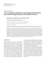
brst ld, brst data, brst en, brst addr, brst done
Input port
Input port
Input port
Input port
Address
generator
Address
generator
rdy, ack, priority
addr, data, rden, wren
addr, data, rden, wren
addr, data, rden, wren
addr, data, rden, wren
req, rel
grant, priority
cfg
wren, addr, data
Priority
arbitration
Mutex
Mutex
Mutex
Mutex
SRAM
Output
FIFO
Output
FIFO
Output
FIFO
Output
FIFO
Figure 3: FIFO-buffered memory block diagram. Arrows show the direction of signal flow for the major blocks in the design. Multiplexers
allow control of various resources to be switched among input ports. The gray bars approximate the pipeline stages in the design.
FIFOs. In general, these words are called tokens.Oneormore
tokens make up a request. A request instructs the memory
module to perform an action and consists of a command to-
ken, and possibly one or more data tokens. The requests is-
sued by a particular processor are always executed in FIFO
order. Concurrent requests from multiple processors may be
executed in any order. If a request results in data being read
from memory, this data is written to the appropriate output
FIFO where it can be accessed by the appropriate block.
5.3.1. Request types
The FIFO-buffered memory supports eight different request
types. Each request type utilizes different resources within
the memory module. In addition, some requests are block-
ing, meaning that they must wait for certain conditions to be
satisfied before they complete. To maintain FIFO ordering of
requests, subsequent requests cannot proceed until a block-
ing request completes.
(1)-(2) Memory read and write requests cause a single
word memory access. The request blocks until the access is
completed. (3)-(4) Configuration requests enable setup of
module ports and address generators. (5)-(6) Burst read and
write requests are used to issue up to 255 contiguous mem-
ory operations using an address generator. (7)-(8) Mutex re-
quest and release commands are used to control exclusive
use of a mutual exclusion primitive—which can be used for
synchronization among input ports or in the implementa-
tion of more complex mutual exclusion constructs.
5.3.2. Input port modes
Each input port in the FIFO-buffered memor y module can
operate in one of three modes. These modes affect how in-
coming memory and burst requests are serviced. Mode infor-
mation is set in the port configuration registers using a port
configuration request. These registers are unique to each in-
put port, and can only be accessed by the port that contains
them.
Address-data mode is the most fundamental input port
mode. In this mode, an input port performs memory reads
and writes independently. The destination for memory reads
is programmable, and is typically chosen so that the output
port and input port connect to the same external block, but
this is not strictly required.
A memory write is performed by first issuing a memory
write request containing the write address. This request must
be immediately followed by a data token containing the data
to be written to memory. In the case of a burst write, the
burst request must be immediately followed by the appropri-
ate number of data tokens. Figure 4(a) illustrates how writes
occur in address-data mode.
A memory read is performed by first issuing a memory
read request, which contains the read address. The value read
Michael J. Meeuwsen et al. 7
Processor
Memory module
Input token stream Address-data mode
.
.
.
Data
Data
Burst write r eq.
Data
Write req.
Data
Write req.
Write req.
Data
To memory
(a)
Processor 0
Processor 1
Memory module
Input token stream Address-only mode
.
.
.
.
.
.
Burst write r eq.
Write req.
Write req.
.
.
.
Write req.
Write req.
Input token stream Data-only mode
Data
Data
Data
.
.
.
Data
Data
Data
Data
Write req.
Data
To memory
(b)
Figure 4: Memory writes in (a) address-data and (b) address-only mode. (a) In address-data mode, each port provides both addresses and
data. Memory writes occur independently, and access to the memory is time-multiplexed. Two tokens must be read from the same input
stream to complete a write. (b) In address-only mode, write addresses are supplied by one port, and data are supplied by another. Memory
writes are coupled, so there is no need to time-multiplex the memory among ports. One token must be read from each input stream to
complete a write.
from memory is then written to the specified output FIFO.
The same destination is used for burst reads.
In address-only mode, an input port is paired with an in-
putportindata-only mode to perform memory writes. This
allows the tasks of address generation and data generation to
be partitioned onto separate external blocks.
In address-only mode, a memory write is performed by
issuing a memory write request containing the write address.
In contrast to operation in address-data mode, however, this
request is not followed by a data token. Instead, the next valid
data token from the input port specified by a programmable
configuration register is written to memory. Synchronization
between input ports is accomplished by maintaining FIFO
order of incoming tokens. It is the programmer’s responsi-
bility to ensure that there is a one to one correspondence be-
tween write requests in the address-only port and data to-
kens in the data-only port. Figure 4(b) illustrates how writes
occur.
An input port in data-only mode acts as a slave to the
address-only input port to which it provides data. All request
types, with the exception of port configuration requests, are
ignored when the input port is in data-only mode. Instead all
incoming tokens are treated as data tokens. The programmer
must ensure that at any one time, at most one input port is
configured to use a data-only port as a data source.
As previously mentioned, the presented memory module
design directly supports memory arrays up to 64 K words.
This is due solely to a 16-bit interface in the AsAP processor,
and therefore a 16-bit memory address in a straightforward
implementation. The supported address space can clearly be
increased by techniques such as widening the interface bus or
implementing a paging scheme.
Another dimension of memory module scaling is to con-
sider connecting more than four processors to a module.
This type of scaling begins to incur significant performance
penalties (in tasks such as port arbitration) as the number of
ports scales much beyond four. Instead, the presented mem-
ory module is much more amenable to replication through-
out an array of processors—providing high throughput to a
small number of local processors while presenting no barri-
ers to the joining of multiple memories through software or
interconnect reconfiguration, albeit with a potential increase
in programming complexity depending on the specific appli-
cation.
6. IMPLEMENTATION RESULTS
The FIFO-buffered memory module described in Section 5
has been described in Verilog and synthesized with a 0.18 µm
CMOS standard cell library. A standard cell implementation
8 EURASIP Journal on Embedded Systems
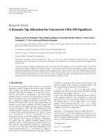
Figure 5: Layout of a 8192-word × 16-bit 0.18 µm CMOS standard
cell FIFO-buffered memory module implementation. The large
SRAM is at the top of the layout and the eight 32-word FIFO mem-
ories are visible in the lower region.
has been completed and is shown in Figure 5. The design is
fully functional in simulation.
Speed, power, and area results were estimated from high-
level synthesis. In addition, the design’s performance was an-
alyzed with RTL level simulation. This section discusses these
results.
6.1. Performance results
System performance was the primary metric motivating the
memory module design. Two types of performance are con-
sidered. First, the system’s peak performance, as dictated by
the maximum clock frequency, peak throughput, and latency
is calculated. A more meaningful result, however, is the per-
formance of actual programs accessing the memory. Both of
these metrics are discussed in the following subsections.
6.1.1. Peak performance
The peak performance of the memory module is a func-
tion of the maximum clock frequency, and the theoretical
throughput of the design. The FIFO-buffered memory mod-
ule is capable of issuing one memory access every cycle, as-
suming that requests are available and their data dependen-
cies are met. In address-data mode, memory writes require
a minimum of two cycles to issue, but this penalty can be
avoided by using address generators or the address-only port
mode, or by interleaving memory requests from multiple
ports. If adequate processing resources exist to supply the
memory module with requests, the peak memory through-
put is one word access per cycle. Synthesis results report a
maximum clock frequency of 555 MHz. At this clock speed,
the memory’s peak throughput is 8.8 Gbps with 16-bit words.
The worst case memory latency is for the memory read
request. There are contributions to this latency in each of the
system’s clock domains. In the external block’s clock domain,
the latency includes one FIFO write latency, one FIFO read
latency, and the additional latency introduced by the mem-
ory port. In the memory’s clock domain, the latency includes
one FIFO read latency, the memory module latency, and one
FIFO write latency.
The minimum latency of the memory module is given
by the number of pipe stages between the input and output
ports. The presented implementation has four pipe stages.
The number of stages may be increased to add address de-
coding stages for larger memories.
The latency of FIFO reads and writes is dependent on the
number of pipe stages used to synchronize data across the
clock boundary between the read side and the write side. In
AsAP’s FIFO design, the number of synchronization stages is
configurable at runtime. When a typical value of three stages
is used, the total FIFO latency is four cycles per side. When
the minimum number of stages is used, the latency is reduced
to three cycles per side. A latency of four cycles is assumed in
this work.
The latency of the memory port depends on the num-
ber of stages introduced between the processor and the mem-
ory to account for wire delays. The minimum latency of the
memory port is two cycles. This latency could be decreased
by integrating the memory port more tightly with the pro-
cessor core datapath. This approach hinders the use of a
prefetch buffer to manage an arbitrary latency from proces-
sor to memory, and is only practical if the latency can be con-
strained to a single cycle.
Summing the latency contributions from each clock do-
main, the total latency of a memory read is,
L
proc
= L
FIFO-wr
+ L
FIFO-rd
+ L
mem-port
,
L
mem
= L
FIFO-rd
+ L
mem-module
+ L
FIFO-wr
,
L
total
= L
mem
+ L
proc
.
(1)
For the presented design and typical configurations, the la-
tency is 10 processor cycles and 13 memory cycles. If the
blocks are clocked at the same frequency, this is a minimum
latency of 23 cycles. Additional latency may be introduced by
processor stalls, memory access conflicts, or data dependen-
cies. The latency is slightly higher than typical L2 cache laten-
cies, which are on the order of 15 cycles [2], due to the com-
munication overhead introduced by the FIFOs. This high la-
tency c an be overcome by issuing multiple requests in a sin-
gle block. Because requests are pipelined, the latency penalty
occurs only once per block.
6.1.2. Actual performance
To better characterize the design’s performance, the memory
module was exercised with two generic and variable work-
loads: a single-element workload and a block workload .The
number of instructions in both test kernels is varied to sim-
ulate the effect of varying computation loads for each appli-
cation. Figure 6 gives pseudocode for the two workloads.
The single-element workload performs a copy of a 1024-
element array and contains three phases. First, a burst write
Michael J. Meeuwsen et al. 9
Write initial array
⎡
⎢
⎢
⎢
⎣
for i = 0 : 1023
mem
wr(a + i) // wr command
wr
data = input // wr data
next i
for i
= 0 : 1023
mem
rd(a + i) // rd command
mem
wr(b + i) // wr command
# NOPs models
additional
computation load
⎡
⎢
⎣
NOP
···
NOP
temp
= rd data // rd data
wr
data = temp // wr data
next i
Read result
⎡
⎢
⎢
⎢
⎣
for i = 0 : 1023
mem
rd(b + i) // rd command
output
= rd data // rd data
next i
(a) Single element workload
for i = 0 : 1023
# NOPs models
additional address
computation load
⎡
⎢
⎣
NOP
···
NOP
mem
wr(a + i) // wr command
# NOPs models
additional data
computation load
⎡
⎢
⎣
NOP
···
NOP
wr
data = input // wr data
next i
# NOPs models
additional address
computation load
⎡
⎢
⎣
NOP
···
NOP
mem
rd(a + i) // rd command
# NOPs models
additional data
computation load
⎡
⎢
⎣
NOP
···
NOP
output
= rd data // rd data
next i
(b) Block workload
Figure 6: Two workloads executed on external processors are used for performance characterization. Pseudo-code for the two workloads is
shown for processors in address-data mode. In each workload, the computational load per memory transaction is simulated and varied by
adjusting the number of NOPs in the main kernel. The block workload is also tested in address-only/data-only mode (not shown here) where
the code that generates memory requests, and the code that reads and wr ites data is partitioned appropriately. mem
rd() and mem wr() are
read and write commands being issued with the specified address. rd
data reads data from the processor’s memory port, and wr data writes
data to the processor’s memory port.
is used to load the source array into the processor. Second,
the array is copied element by element, moving one element
per loop iteration. Finally, the resulting array is read out with
a burst read. The number of instructions in the copy kernel is
varied to simulate various computational loads. The single-
element kernel is very sensitive to memory read latency be-
cause each memory read must complete before another can
be issued. To better test throughput rather than latency, the
block test is used. This workload first writes 1024 memory
words, and then reads them back.
In addition, three coding approaches are compared. The
first uses a single processor executing a s ingle read or write
per loop iteration. The second uses burst requests to per-
form memory accesses. The third approach partitions the
task among two processors in address-only and data-only
modes. One processor issues request addresses, while the
other manages data flow. Again, the number of instructions
in each kernel is varied to simulate various computational
loads.
Figure 7 shows the performance results for the single-
element workload running on a single processor at different
clock speeds. For small workloads, the performance is domi-
nated by the memory latency. This occurs because each itera-
tion of the loop must wait for a memory read to complete be-
fore continuing. A more efficient coding of the kernel could
overcome this latency using loop unrolling techniques. This
may not always be practical, however, due to limited code and
data storage. The bend in each curve occurs at the location
where the memory latency is matched to the computational
workload. Beyond this point, the performance scales with
the complexity of computation. The processor’s clock speed
has the expected effectonperformance.Athighfrequen-
cies, the performance is still limited by memory latency, but
larger workloads are required before the computation time
overcomes the read latency. The latency decreases slightly at
higher processor frequencies because the component of the
latency in the processor’s clock domain is reduced. The slope
of the high-workload portion of the curve is reduced because
the relative impact of each additional instruction is less at
higher frequencies.
For highly parallel workloads, the easiest way to im-
prove performance is to distribute the task among multi-
ple processors. Figure 8 shows the result of distributing the
single-element workload across one, two, and four proces-
sors. In this case, the 1024 copy operations are divided evenly
among all of the processors. When mapped across multiple
processors, one processor performs the initial array write,
and one processor performs the final array read. The re-
mainder of the computation is distributed uniformly among
the processors. Mutexes are used to ensure synchronization
10 EURASIP Journal on Embedded Systems
706050403020100
Additional computation load
0
1
2
3
4
5
6
7
8
9
×10
4
Execution time (memory cycles)
4
2
1.3333
1
Ideal
Figure 7: Effect of computational load and clock speed on perfor-
mance. The figure shows the execution time of the single-element
workload for a single processor clocked at 1, 1.33, 2, and 4 times
the memory speed. The dotted line represents the theoretical maxi-
mum performance for the workload operating on a single processor
clocked at the same speed as the memory.
between the initialization, copy, and read-out phases of
execution.
When the single-element workload is shared among pro-
cessors, the application’s performance is increased at the cost
of additional area and power consumed by the additional
processors. For small computation loads, the effective read
latency is reduced. Although each read still has the same la-
tency, the reads from each processor are issued concurrently.
Hence, the total latency suffered scales inversely with the
number of processors used. For loads where latency is dom-
inated by computation cost, the impact of the computation
is reduced, because multiple iterations of the application ker-
nel run concurrently on the various processors. Note that the
point where computation load begins to dominate latency is
constant, regardless of the number of processors used. The
relative latency depends only on the relative clock speeds of
the processors and memories, and not on the distribution of
computation.
Figure 9 shows the performance of the three addressing
schemes for the block workload when the processors and
memory are clocked at the same frequency. For small work-
loads, the address-data mode solution is dominated by read
latency and write workload. Because writes are unaffected
by latency, the computation load has an immediate effect.
For large workloads, the execution time is dominated by the
computation load of both reads and writes. To il lustrate the
appropriateness of the synthetic workloads, three key algo-
rithms (1024-tap FIR filter, 512-point complex FFT, and a
706050403020100
Additional computation load (processor cycles)
0
1
2
3
4
5
6
7
8
9
×10
4
Execution time (memory cycles)
1 processor
2 processors
4 processors
Figure 8: Effect of number of processors on performance. The fig-
ure shows the execution time of the single-element workload for 1,
2, and 4 processors clocked at the same frequency as the memory.
The execution time for each case includes some fi xed overhead to
initialize and read the source and destination arrays. Multiple pro-
cessor cases have additional overhead for synchronization among
processors.
viterbi decoder) are modeled and shown on the plot. While
these applications are not required to be written conforming
to the synthetic workloads, the versions shown here are very
reasonable implementations.
The address generator and address-only/data-only solu-
tions decouple the generation of memory read requests from
the receipt of read data. This allows requests to be issued far
in advance, so the read latency has little effec t. There is also a
slight performance increase because the number of instruc-
tionsineachkernelisreduced.
The address generator solution outperforms the single
cycle approach, and does not require the allocation of ad-
ditional processors. This is the preferred solution for block
accesses that can be mapped to the address generation hard-
ware. For access patterns not supported by the address gen-
erators, similar performance can be obtained by generating
the addresses with a processor in address-only mode. This re-
quires the allocation of an additional processor, which does
incur an additional cost.
Address only mode allows arbitrary address generation
capability at the cost of an additional processor. This method
eases implementation of latency-insensitive burst reads with-
out requiring partitioning of the data computation. This
method is limited by the balance of the address and data
computation loads. If the address and data processors run
at the same speed, whichever task carries the hig hest compu-
tation load dominates the system performance. This can be
seen in Figure 10.
Michael J. Meeuwsen et al. 11
6050403020100
Computation load
0
5
10
15
×10
4
Execution time (memory cycles)
One addr-data proc., for pseudo app.
One proc. with addr generat or, for pseudo app.
Two addr-only/data-only procs., for pseudo app.
One addr-data proc., for real apps
Two addr-only/data-only procs., for real apps
Viterbi decoder
(one trellis with 512 ACS calc.)
512-pt complex FFT (one stage)
1024-tap FIR
Figure 9: Effect of address mode on block performance. The figure
shows the execution time of the block workload for a single proces-
sor in address-data mode, a single processor utilizing address gener-
ator hardware, and two processors, one in address-only mode and
one in data-only mode. Both the address generator and address-
only mode solutions outperform the address-data mode solution
if the work load is dominated by the memory latency. Note that
the address generator and address-only performances are roughly
equal. Three real applications are shown to validate the synthetic
workloads.
Partitioning an application among multiple processors in
address-data mode typically outperforms a mapping using
the same number of processors in address-only or data-only
mode. This occurs because the number of iterations of the
application kernel required per processor is reduced. This
reduces the application’s sensitivity to computation loads.
Address-only mode is most useful when address computa-
tion and data computation are of similar complexities, when
code space limitations prevent the two tasks from sharing the
same processor, or w hen the application lacks adequate data
parallelism to distribute the computation otherwise.
Figure 11 compares the performance of the block work-
load when computation is distributed across two processors.
A mapping with two address-data mode processors outper-
forms address-only and data-only partitioning in most cases.
If address and data computation loads are mismatched, the
greater load dominates the execution time for the address-
only/data-only mapping. When the address and data compu-
tation loads are similar, the performance gap for the address-
only mode mapping is small. Furthermore, for very small
computation loads, the address-only mode mapping outper-
forms the address-data mode mapping because each loop it-
eration contains fewer instructions.
50403020100
Address computation load (processor cycles)
0
2
4
6
8
10
12
14
16
18
×10
4
Execution time (memory cycles)
Single processor, data computation = 20
Data computation
= 0
Data computation
= 20
Data computation
= 40
Figure 10: Effect of address load on address-only mode perfor-
mance. The figure shows the execution time of the block workload
for a single processor in address-data mode, and two processors,
one in address-only mode and one in data-only mode. The address
calculation workload is varied for each case. Each curve represents
a fixed data computation workload. The memory module and pro-
cessors share the same clock frequency.
6.2. Area and power tradeoffs
As with most digital IC designs, area and power are closely
related to performance. Generally, performance can be in-
creased at the expense of area and power by using faster de-
vices or by adding parallel hardware. Although the perfor-
mance of the FIFO-buffered memory module was the first
design priority, the power and area results are acceptable.
The results discussed are for high-level synthesis of the Ver-
ilog model. Some increase is expected during back-end flows.
Dynamic power consumption was estimated using activity
factors captured during RTL simulation.
6.2.1. Area results
The results of the synthesis flow provide a reasonable esti-
mate of the design’s area. The design contains 9713 cells, in-
cluding hard macros for the SRAM core and FIFO memo-
ries. With an 8 K-word SRAM, the cell area of the synthesized
design is 1.28 mm
2
. This is roughly equivalent to two and a
half AsAP processors. The area after back-end placement and
routing is 1.65 mm
2
.
The area of the FIFO buffered memory module is domi-
nated by the SRAM core, which occupies 68.2% of the mod-
ule’s cell area. This implies a 32.8% area overhead to imple-
ment the FIFO-buffered design, rather than a simpler SRAM
12 EURASIP Journal on Embedded Systems
50454035302520151050
Address computation load (processor cycles)
0
2
4
6
8
10
12
×10
4
Execution time (memory cycles)
Address-data, data computation load = 0
Address-data, data computation load
= 20
Address-only, data computation load
= 0
Address-only, data computation load
= 20
Figure 11: Equal area comparison of address modes. The figure
shows the execution time of the block workload for two parallel pro-
cessors in address-data mode, and two processors, one in address-
only mode and one in data-only mode. The address calculation
workload is varied for each case. Each curve represents a fixed data
computation workload. The memory module and processors share
the same clock frequency.
interface. This overhead is similar to that reported by Mai
et al. for a Smart Memories system with the same mem-
orycapacity[12]. The distribution of area among the ma-
jor blocks of the design is show n in Figure 12. The presented
implementation has an SRAM of 8 K words, but the synthe-
sized source design, however, is capable of addressing up to
64 K words. Conservatively assuming the memory size scales
linearly, a 64 K-word memory would occupy 94.5% of the
module’s area. This implies an overhead of only 5.5%, which
is easily justified by the performance increase provided by the
shared memory.
6.2.2. Power results
In general, accurate power estimation is difficult without
physical design details. A reasonable estimate of the design’s
power consumption can be taken from high level synthe-
sis results and library information. The main limitation of
power estimation at this level is obtaining accurate switching
activity for the nodes in the design. Switching activity was
recorded for the execution of a four processor application
that computes c
j
= a
j
+2b
j
for 1024 points. This applica-
tion exercises most of the design’s functionality.
Power Compiler reports the relative power of each sub-
module as shown in Figure 13. Absolute power estimates
fromthetoolarebelievedtobelessaccuratesowepresent
the relative numbers only. Of the total power consumption,
Other (5%)
Address gen. (2%)
Input port (5%)
Output FIFOs (10%)
Input FIFOs (10%)
SRAM (68%)
Figure 12: Area distribution among submodules. The relative cell
area of each group of submodules is shown. The SRAM used in this
designis8Kwords.TheSRAMconsumes68%ofthearea;thefour
input FIFOs occupy 10%; the four output FIFOs occupy 10%. The
“other” category includes modules not shown such as configura-
tion, mutex, arbiter, and clock oscillator.
Other (4%)
Address gen. (6%)
Inputport(23%)
Output FIFO (14%)
SRAM (14%)
Input FIFO (39%)
Figure 13: Relative power consumption neglecting clock power of
submodules. The power is dominated by the input FIFOs (39%)
and input ports (23%) as these are the most active blocks in the
design. The dynamic power of the SRAM cell is relatively low, but
matches well with the datasheet value.
57.1 nW is attributed to cell leakage power. The breakdown
for leakage power is shown in Figure 14.
7. CONCLUSION
The design of an asynchronously sharable FIFO-buffered
memory module has been described. The module allows a
high capacity SRAM to be shared among independently-
clocked blocks (such as processors). The memory module
shares its memory resources with up to four blocks/process-
ors. This allows the memory to be used for interprocess com-
munication or to increase application performance by par-
allelizing computation. The addition of addressing modes
Michael J. Meeuwsen et al. 13
Other (1%)
Output FIFO (42%)
SRAM (14%)
Input FIFO (43%)
Figure 14: Relative leakage power of submodules. As expected, the
leakage power is dominated by the memory cells. The eight FIFOs
(85%) and the SRAM core (14%) consume nearly all of the mod-
ule’s leakage power.
and hardware address generators increases the system’s flexi-
bility when mapping many applications. The FIFO-buffered
memory module was described in Verilog, and synthesized
with a 0.18 µm CMOS standard cell librar y. A design with
an 8 K-word SRAM has a maximum operating frequency of
555 MHz, and occupies 1.2 mm
2
based on high-level synthe-
sis results. The memory module can service one memory
access each cycle, leading to a peak memory bandwidth of
8.8 Gbps.
ACKNOWLEDGMENTS
The authors thank E. Work, T. Mohsenin, R. Krishnamurthy,
M. Anders, S. Mathew, and other VCL members; and grate-
fully acknowledge support from Intel, UC MICRO, NSF
Grant no. 0430090, and a UCD Faculty Research Grant.
REFERENCES
[1] A. W. Burks, H. H. Goldstine, and J. von Neumann, “Prelimi-
nar y discussion of the logical design of an electronic comput-
ing instrument,” in Collected Works of John von Neumann,A.
H. Taub, Ed., vol. 5, pp. 34–79, The Macmillan, New York, NY,
USA, 1963.
[2]J.L.HennessyandD.A.Patterson,Computer Architecture,
A Quantitative Approach, chapter Memory Hierarchy Design,
Morgan Kaufmann, San Francisco, Calif, USA, 3rd edition,
2003.
[3] Z. Yu, M. J. Meeuwsen, R. Apperson, et al., “An asynchronous
array of simple processors for DSP applications,” in IEEE Inter-
national Solid-State Circuits Conference (ISSCC ’06), pp. 428–
429, San Francisco, Calif, USA, February 2006.
[4] R. Banakar, S. Steinke, B S. Lee, M. Balakrishnan, and P. Mar-
wedel, “Scratchpad memory: a desig n alternative for cache
on-chip memory inembedded systems,” in Proceedings of the
10th International Symposium on Hardware/Software Codesign
(CODES ’02), pp. 73–78, Estes Park, Colo, USA, May 2002.
[5] P. R. Panda, N. D. Dutt, and A. Nicolau, “On-chip vs. off-
chip memory: the data partitioning problem in embedded
processor-based systems,” ACM Transactions on Design Au-
tomation of Electronic Systems, vol. 5, no. 3, pp. 682–704, 2000.
[6] D. Patterson, T. Anderson, N. Cardwell, et al., “A case for in-
telligent RAM,” IEEE Micro, vol. 17, no. 2, pp. 34–44, 1997.
[7] K. Mai, T. Paaske, N. Jayasena, R. Ho, W. J. Dally, and M. A.
Horowitz, “Smart memories: a modular reconfigurable archi-
tecture,” in Proceedings of the 27th Annual International Sym-
posium on Computer Architecture (ISCA ’00), pp. 161–171,
Vancouver, BC, Canada, June 2000.
[8] B. M. Baas, “A parallel programmable energy-efficient archi-
tecture for computationally-intensive DSP systems,” in Pro-
ceedings of the 37th Asilomar Conference on Signals, Systems and
Computers (ACSSC ’03), vol. 2, pp. 2185–2192, Pacific Grove,
Calif, USA, November 2003.
[9] M.J.Meeuwsen,O.Sattari,andB.M.Baas,“Afull-ratesoft-
ware implementation of an IEEE 802.11a compliant digital
baseband transmitter,” in Proceedings of IEEE Workshop on Sig-
nal Processing Systems (SIPS ’04), pp. 124–129, Austin, Tex,
USA, October 2004.
[10] D. M. Chapiro, Globally-asynchronous locally-synchronous sys-
tems, Ph.D. thesis, Stanford University, Stanford, Calif, USA,
October 1994.
[11] R. W. Apperson, “A dual-clock FIFO for the reliable transfer
of high-throughput data between unrelated clock domains,”
M.S. thesis, University of California, Davis, Davis, Calif, USA,
2004.
[12] K. Mai, R. Ho, E. Alon, et al., “Architecture and circuit tech-
niques for a 1.1-GHz 16-kb reconfigurable memory in 0.18-
µm CMOS,” IEEE Journal of Solid-State Circuits, vol. 40, no. 1,
pp. 261–275, 2005.