Báo cáo hóa học: " Research Article From IEC 61131 to IEC 61499 for Distributed Systems: A Case Study" doc
Bạn đang xem bản rút gọn của tài liệu. Xem và tải ngay bản đầy đủ của tài liệu tại đây (776.17 KB, 8 trang )
Hindawi Publishing Corporation
EURASIP Journal on Embedded Systems
Volume 2008, Article ID 231630, 8 pages
doi:10.1155/2008/231630
Research Article
From IEC 61131 to IEC 61499 for
Distributed Systems: A Case Study
Christian Gerber,
1
Hans-Michael Hanisch,
1
and Sven Ebbinghaus
2
1
Institute for Computer Science, Martin Luther University Halle-Wittenberg, 06099 Halle, Germany
2
LAE Engineering GmbH, Massengasse 13, 69226 Nussloch, Germany
Correspondence should be addressed to Christian Gerber,
Received 30 January 2007; Revised 1 August 2007; Accepted 8 October 2007
Recommended by Jose L. Martinez Lastra
A new concept for distributed control systems based on the new IEC 61499 standard is tested in this work in cooperation with LAE
Engineering GmbH, a medium-sized company. Based on a catalogue of requirements, a customer-related testbed is developed. In
the following this testbed is used as a reference to realise an IEC 61499 compliant-distributed control system based on PC technics.
By doing this, rules are defined to convert user-owned IEC 61131 function blocks to IEC 61499 compliant function blocks. Con-
cluding, some trends for IEC 61499-based distributed control systems will be summarised.
Copyright © 2008 Christian Gerber et al. This is an open access article distributed under the Creative Commons Attribution
License, which permits unrestricted use, distribution, and reproduction in any medium, provided the original work is properly
cited.
1. THE PROBLEM
Especially for medium-sized companies, it will become more
and more important to create solutions of automation prob-
lems that are optimally coordinated with the customer in or-
der to maintain the competitiveness also in future. Thereby,
these medium-sized companies can feature themselves by
manufacturerer independence and usage of the hardware
that the customer prefers, which maybe replaced in only
some cases by better matching components. It is also pos-
sible in smaller projects to use hardware that already exists
at the customer but is not working at full capacity. Doing
this, the acquisition cost of new hardware is reduced, and a
distributed system is created. These points would require an
enormous know how of the staff and the existence of many
Engineering Support Systems to program and parameterize
control units of different manufactures. A better way of cre-
ating a distributed system would be to have one Engineering
Support System and to program and parameterize as many
as possible different control and visualisation units by using
automation components. Furthermore, it should be possi-
ble to exchange the created automation components easily.
Last but not least it should be possible to plan the optimal
usage of the communication bandwidth and the computing
power. This can be achieved by transferring only changed
data points and executing only algorithms with changed in-
put values.
Additionally, it should be possible to develop the control-
ling components independently from the manufacturer and
to encapsulate the company’s own intellectual property. All
components forming the control system can then be stored
in a company-wide library. This will allow to replace a dam-
aged or not correctly working component easily by a new one
and to download the control algorithms and parameterisa-
tion automatically by the control system itself (Plug and Par-
ticipate).
Although such approaches have been sketched by many
authors before [1–3], application in practice is rather sparse.
This contribution is a first step to pave the way towards those
goals.
2. NEW POINTS OF VIEW FROM THE IEC 61499
In a first step to support these new requirements, the In-
ternational Electrotechnical Commission (IEC) launched the
International Standard IEC 61499, which became official in
2005. This new standard should be an extension to the well-
known and used standard IEC 61131 for programming logic
controllers. So it is possible to use the programming lan-
guages instruction list, ladder logic, and structured text as
well as high-level languages like C, java, and Delpi to create
the control algorithms for the basic function blocks of IEC
61499. Furthermore, it is possible to describe an IEC 61131
configuration by using the defined software model of IEC
2 EURASIP Journal on Embedded Systems
61499. The differences between both are the new system layer
at the top, the changed function block interface, and the in-
troduced execution control chart (ECC) at the root of the
software model [4].
The new system layer potentiates the development of the
whole control system with all controllers, I/Os, visualisation,
and data logging devices in one project, which will make it
easier to realise changes in the equipment and communica-
tion. Another effort in cases of trouble is to simply get the
system overview and to backup all project files.
Furthermore, the execution control is changed from
cyclic to an event-driven one [5]. This allows to reduce the
computing power and the communication bandwidth to a
necessary minimum if only algorithm with changed input
data is executed and only data packages with changed data
values are transmitted.
Concerning the self-reconfiguration of a control system
in cases of disturbance or any other change in the produc-
tion environment, the IMS Research and Development Pro-
gram has accomplished the research projects PABADIS [6]
und HMS [7]. To match the different partial results of these
and other global, European, and national projects, the R&D
initiative OOONeida was founded. The aim is the creation
of a technological infrastructure for a new open knowledge
economy for automation components and automated indus-
trial products [8].
To protect the own intellectual property at this new open
knowledge economy, the guideline of encapsulation and hid-
ing was adopted from the IEC 61131 to the IEC 61499. To
guarantee the reusability and portability of the once devel-
oped components between the different Engineering Sup-
port Systems, the second part of the IEC 61499 defines the
requirements for the Engineering Support System.
3. CUSTOMER-RELATED TESTBED
For the further work, a state-of-the-art testbed related to
the customers requirements was established in cooperation
with LAE Engineering. It is supposed to show what is cur-
rently done concerning communication, manufacturer inde-
pendency, and programming of control systems.
3.1. Communication: industrial ethernet
In most manufacturing plants, field buses like AS-Interface,
CAN, and Profibus are the currently used communication
platform, but there is a widely accepted trend to use Indus-
trial Ethernet in future. The manufacturers of automation
technology as well as the customers support this trend, be-
cause Ethernet in combination with new transport protocols
like Powerlink, Ethercat, Profinet, and so forth offers more
opportunities by the same rate of actualisation. So it will be
possible to use the different communication media copper,
optic and wireless fiber with data transfer rates up to 1 giga-
bit per second.
3.2. Used hardware
Based on the results of a market research, the systems from
Bernecker + Rainer Industrie-Elektronik GmbH (B&R) and
Phoenix Contact GmbH&Co.KG (Phoenix) were used for
the testbed. From B&R we used a combined visualisation and
control unit (PowerPanel 200), a PLC (System2003, CP476-
DP), and a modular remote I/O (X20) with 6 digital in- and
outputs and 2 analog inputs. From the Phoenix products a
PLC (ILC350-PN), one compact and one modular remote
I/O (ILB PN 24, FL IL 24 BK-PN-PAC), an interbus proxy
(FL PN/IBS) combined with I/Os, and two modular and
manageable switches (FL SWITCH MM HS) were chosen.
3.3. Control functionality
The control functionality described in the following is de-
veloped together with LAE Engineering. Main business seg-
ments of this company are calendering techniques, power
generation, and building automation. That is why only main
control operations from all of these segments are realised and
not one complete control system of a calender or a block-type
thermal power station.
From the segment calendering techniques, a function
block to control an engine with one rotation direction and
a watchdog timing to detect any disturbance is used. In an-
other function block, a start up sequence of a calender ac-
cording to DIN EN 12301 is implemented. The different steps
of these sequences are horn active, retention time, andrelease
of start.
To record the alarms, an alarm management consisting
of two or more function blocks is implemented at every con-
trol unit. All alarm activations are registered in groups of 8
by function blocks of the type AlarmDetection. These func-
tion blocks communicate with the function block of the type
NewAlarm, which is used to register the occurrence of one or
more new alarms, quit all active alarms or only to turn off the
horn.
The most commonly used function blocks from the de-
partment of power generation have the functionality to cal-
culate the average value of a data point and to register the
daily and monthwise power consumption. To test a function
block with a wide-spread functionality and huge memory
consumption, the function block of the type PZN
Archiv was
also taken from the power generation department. With this
block, it is possible to register the power production per 15
minutes of the last 24 hours and to send the last value to the
visualisation, which sends a rising edge to a boolean input to
get the next value.
For communication purpose between the control units,
a bidirectional Ethernet-based client server architecture is
used and the TCP/IP packets are sent every 500 milliseconds,
whether the included data points have changed or not. Thus,
the consumed communication bandwidth is every time the
same.
Because of getting a faster communication between the
control unit and the remote I/Os, the Ethernet-based proto-
cols Profinet I/O and Powerlink are used. Thus, it is possible
to get the current state of each remote I/O every 10 millisec-
onds to the appropriate control unit.
4. CONVERTING THE TESTBED TO IEC 61499
At the second part of the work it should be demonstrated that
the control functionality of the testbed can also be realised
Christian Gerber et al. 3
A0
A1-EngineOn
A2
A3
Outputs FL BK 24
E0-AckEngine3
E1-AckFailureEngine
E2
E3-EM-Stop
Inputs FL BK 24
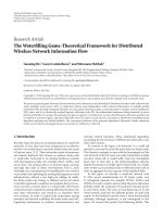
Figure 1: Graphical interface of a remote I/O.
with a distributed control system based on the IEC 61499
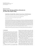
standard. The remote I/Os are realised as several devices with
a graphical interface for boolean and integer in- and out-
puts as shown in Figure 1 and the whole control system is PC
based. The communication between the remote I/Os and the
control devices is based on UDP-datagrams, because of miss-
ing communication function blocks realising the Ethernet-
based protocols Profinet I/O or Powerlink.
In the following the control system will be described top
down with the beginning at the system layer. But the focus
is directed to the translation of the function blocks to IEC
61499, because they are the skeleton of the distributed con-
trol system and realise the control functionality. Because of
this we will define some converting rules in Section 4.2 to
build in further work an automatic translator.
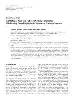
4.1. System layer
The highest layer of a distributed system is the system layer
shown in Figure 2. It includes the configuration of all de-
vices like control devices, remote inputs and outputs, human
machine interfaces, and data logging devices. To support the
system integrator in building and in cases of disturbance in
checking the communication connection between the dif-
ferent devices, network segments represented by arrows are
used. Thus, they are used only for documentation purpose at
the system layer.
4.2. Control components: function blocks
In this section of the work, the translation from IEC 61131 to
61499 will be shown exemplarily at some function blocks. As
a conclusion, some rules how to convert IEC 61131 function
blocks to IEC 61499 function blocks will be defined.
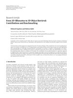
4.2.1. FB—AverageCont
Both function blocks in Figure 3 represent an average value
calculator for one data point, but the left is IEC 61131 based,
and the other, at the right side, is IEC 61499 based. Both of
them have the same data interface, but the right function
block is extended by a management interface consisting of
two event pairs. The event pair INIT-INITO is used to trig-
ger a state change at the ECC and therefore the execution of
the initialisation algorithm by occurring of an event at INIT
and to send an information about the termination of this al-
gorithm by the event output INITO. The same is done with
REQ-CNF which triggers the state change to the ECState with
the main algorithm of the function block.
The programming language of the algorithms is up to the
function block developer and could be different at each al-
gorithm. So it is possible to combine the advantages of low
level programming languages like IL, LD, FuB, and ST with
the advantages of high level programming languages like C,
Java, and Delphi in one function block. Another advantage of
this liberty is a smooth change from IEC 61131 to IEC 61499
for the system integrators as well as for the system distributer.
Because of that it was possible to copy the source code for the
INIT and REQ algorithm from the IEC 61131 function block
to the IEC 61499 shown in Algorithm 1.
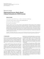
4.2.2. FB—Counter
The function block Counter is used for the registration of the
current daily and monthwise power consumption by using a
rising edge at the data input Input. This rising edge of a data
point at a remote I/O could be detected with the function
block E
R TRIG, defined in annex A of the IEC 61499-1. The
output event E0 of this function block has to be connected
with the event input REQ of the new IEC 61499-based func-
tion block Counter, shown at the rigth side of Figure 4.
Because there is also an edge detection performed for the
boolean inputs DayChange and MonthChange, they are con-
verted to event inputs of the new function block. Further-
more, these edge detections allowed or denied the execution
of several code fragments. Thus, this code fragments should
be translated into several algorithms and associated inside an
ECAction with an ECstate. This ECstate can only be reached
from the ECinitialstate by the occurrence of an event at the
converted event input.
According to the IEC 61499, each event input can be
linked with all data inputs, which leads to a sampling of all
data inputs by the occurrence of an event at the event in-
put. However, the linked set of data inputs should be cut to a
minimum, to reduce the necessary calculation power and ex-
ecution time. Thus, this set should only contain the required
data inputs and the changed data outputs. At the example of
Figure 4, the event inputs Day- and MonthChange are only
linked with data input PulseRatio, because the triggered al-
gorithm only requires this updated value. Contrary to this,
the algorithm executed by the occurrence of the event Set-
Counter only requires the updated values of the data inputs
SetCounterValue and CounterM ax.
4.2.3. FB—Engine
The two function blocks in Figure 5 realise the functional-
ity of controlling an engine with one rotation direction and
a watchdog timer to detect any disturbance as well as the
acknowledgment of the operation of the engine for visual-
isation. For the realisation of a runtime supervision of the
starting, stopping, and short signal interruptions, the timing
function block TON is used.
To realise this functionality with an IEC 61499 function
block, the composite function block in Figure 6 has to be
created. This composite function block is built up by using
the function block FB
Engine Body with the main function-
ality, extended by an event output to start and stop the timer
and an event input to register the expiration of the timer. As
4 EURASIP Journal on Embedded Systems
“141.48.159.195:61499”
[800, 0, 310, 200]
MGR ID
GRID
BOUNDS
RMT
FRAME
ILB PN 24
“141.48.159.196:61498”
[800, 200, 310, 200]
MGR ID
GRID
BOUNDS
RMT
FRAME
FL BK 24
“141.48.159.194:61497”
[800, 400, 310, 200]
MGR ID
GRID
BOUNDS
RMT
FRAME
IBS
Profinet
and TCP UDP IP: Ethernet
“141.48.159.201:61494”
[400, 0, 200, 500]
MGR ID
GRID
BOUNDS
RMT FRAME
PP 200
“141.48.159.199:61496”
[500, 0, 200, 500]
MGR ID
GRID
BOUNDS
RMT
FRAME
ILC 350 PN
CAN: LocalBus
“141.48.159.200:61493”
[400, 500, 310, 200]
MGR ID
GRID
BOUNDS
RMT
FRAME
X20
“141.48.159.197:61495”
[200, 0, 200, 500]
MGR ID
GRID
BOUNDS
RMT
FRAME
CP476DP
“141.48.159.198:61492”
[0, 0, 200, 500]
MGR ID
GRID
BOUNDS
RMT
FRAME
Visu Start
Powerlink: Ethernet
Figure 2: System layer of the testbed.
Average Average
We ig ht
Old Va l ue
New
Va l u e
FC
Average Cont
FC
Average Cont1
(a) IEC 61131
Event
Event
Real
Real
INIT
REQ
INITO
CNF
FB
Average Cont
New
Va l u e Ave ra g e
We ig h t
Old Va l u e
Real
Event
Event
(b) IEC 61499
Figure 3: Function block for the average value.
Average := New Va lue;
(a) INIT
Average :
= (Weight Old Val ue
Average + New Value)/
(Weight
Old Va lu e + 1 )
(b) REQ
Algorithm 1:AlgorithmfortheaveragevaluecalculationinST.
timer, the function block E Delay is used, which is defined in
annex A of the IEC 61499. If the value of a boolean condition
like EngineOn XOR AckOn causes the start and the termina-
tion of the timer, they could be realised with standardised
basic function blocks inside the composite function block.
A positive and a negative edge detection is performed for
the boolean data input Start of the IEC 61131-based func-
tion block. According to the section before, this can be done
using the function blocks E
R TRIG and E F TRIG. The two
output events can be merged by means of the function block
E
Merge, but it is better to avoid this and to use the two events
Start and Stop of the new function block instead. This makes
it possible to have the ECCinitialstate always activated and to
associate one successor with the stopping and another suc-
cessor with the starting algorithm.
4.2.4. FB—StartUpChain
To control a start-up sequence of a calender according to DIN
EN 12301, the function blocks in Figure 7 are used. The horn
is activated first for the defined time at the data input TIME1.
Afterwards, there is a time gap of the time defined at TIME2
for the service personal to vacate the calender. After this it
is possible to start the calender during the time TIME3.If
TIME3 expires without starting the calender, the chain must
be started again.
The described control sequence is implemented in the
IEC 61131 function block by linking three switch-on delay
function blocks. As described in the section before, these
timer function blocks could be converted to function blocks
of the type E
Delay. Afterwards, the output event EO of the
expired timer has to be connected with the event input Start
of the following timer.
Because there is only an edge detection done for the
boolean input Start, it is possible to use the same data in-
terface for the new function block and to extend it with the
management interface as described in Section 4.2.1.
4.2.5. FB—AlarmDetection
The function block AlarmDetection is used to register differ-
ent alarms in groups of eight and to save them at a byte vari-
able. The activation of the eight different alarms occurs by a
low signal or if the logic is inverted by a high signal.
Beside this, the function block provides the opportunity
to register each unacknowledged alarm. The reset of the ac-
knowledgment could be done by the event input Ack.
The bitwise addressing to set, reset, and write a single
alarm and acknowledgment bits to the byte variables as well
as the reading of the single bits out of the byte variables has
to be done with different bit masks and the boolean combi-
nation with the source byte.
Christian Gerber et al. 5
SetCounter SetCounter
CounterMAX
SetCounterValue MonthCounterLMonth
PulseRatio MonthCounter
MonthChange DayCounterYesterday
DayChange DayCounter
Input Counter
FB Counter
FB
Counter 1
(a) IEC 61131
Event
Event
Event
Event
Event
Real
Real
Real
INIT
REQ
INITO
CNF
DayChange ValueDay
MonthChange ValueMonth
SetCounter CounterSet
FB
Counter
PulseRatio Counter
SetCounterValue DayCounter
CounterMAX DayCounterYesterday
MonthCounter
MonthCounterLMonth
Real
Real
Real
Real
Real
Event
Event
Event
Event
Event
(b) IEC 61499
Figure 4: Function block to count the power consumption.
FirstCycle
Ack
Delay
AckFaliure
AckOn
Start
FB
Engine
FB
Engine 1
EngineOn
VisuOn
GroupSignalFail
DelayFaliure
Delayactual
(a) IEC 61131
Event
Event
Event
Event
Bool
Bool
Time
Start
Stop
CNF
Ack
REQ
FB
Engine
AckOn
AckFailure
Delay
DelayFailure
GroupSignalFail
VisuOn
EngineOn
Bool
Bool
Bool
Bool
Event
(b) IEC 61499
Figure 5: Function block for controlling an engine.
AckOn
In2
In1 Out
FB
XOR
EI EO
REQ
Flag
Set
QI
E
F TRIG
EI EO
F TRIG Flag
QI
E
R TRIG
EI EO
R
TRIG Flag
Delay
DT
E
Delay
Stop
Start EO
Timer
AckFailure AckFailure
AckOn
AckOn
DelayFailure
DelayFailure
GroupSignalFail GroupSignalFail
VisuOn VisuOn
EngineOn
FB Engine body
EngineOn
Timer
expired
REQ REQ
Stop Stop
StartStart
Timer
start stop
AckAck
CNF CNF
FB
Engine
Figure 6: Composite function block for controlling an engine.
TIME3
TIME2
TIME1
Start
TimeEnable
TimeRetention
TimeHorn
Enable
Horn
FB
StartUpChain
FB
StartUpChain 1
(a) IEC 61131
Event
Event
Time
Time
Time
TIME3
TIME2
TIME1
TimeEnable
TimeRetention
TimeHorn
Enable
Horn
FB
StartUpChain
IND
CNF
INIT INITO
Start
Time
Time
Time
Bool
Bool
Event
Event
Event
(b) IEC 61499
Figure 7: Function block start up chain.
6 EURASIP Journal on Embedded Systems
REQ REQ
REQ
CNF
1
Start
1
INIT
1
INIT INIT INITO
AckAlarm
AckHorn
HornAcknowledgement
1
AlarmAcknowledgement
HornAck CNF
AlarmAck Ack
Figure 8: ECC of alarm control function block.
4.2.6. FB—NewAlarm
The activation of the horn by the occurrence of any new
alarm and the acknowledgment of the horn as well as all ac-
tivealarmscanbedonewiththefunctionblockNewAlarm.
As shown in Figure 8 the ECtransition to the successor
of the ECstate reached by AckAlarm has no condition and
is therefore always true. This is done because this successor
is reached from the ECinitialstate by the event AckHorn and
resets the data output HornOn, which is also a part of the
AckAlarm functionality. Before this, the output event Ack has
to be published. This event output is linked with the input
event Ack of all function blocks, which register the alarms, by
using the event splitter E
SPLIT, defined in annex A of the
IEC 61499-1.
4.2.7. FB—PZN
Archive
For the implementation of a ring buffer for 24 hours and 4
measured values per hour, the function block in Figure 9 is
used. Furthermore, the oldest and not taken over data pair
consisting of the station number, a time stamp, and the con-
sumed or produced power is presented at the data outputs.
The consumed or produced power is calculated by the num-
ber of positive edges at the boolean input Input and the val-
ues of TransformerConst and TransmitterConst.
By reseting the boolean in- and output Flag of the IEC
61131 function block, a take over of the data and a request for
new data is signaled. If there is new data available, the func-
tion block will set the boolean input and output Flag again.
By converting to IEC 61499, this boolean input and output is
transformed to an event input and an event output.
It should be noticed that it is possible to copy and paste
the source code of the original function block into one algo-
rithm, but it is better to separate the source code according to
rule 3.1 in different algorithms. By doing this, the algorithms
are shorter, easier to validate, and better to understand, but
the ECC for controlling the algorithms will get more com-
plex.
4.3. Translation rules
Due to the earlier explanations in this section, we define the
following general rules for the translation of IEC 61131 func-
tion blocks to IEC 61499 ones.
Rule 1
The same data interface should be used for the IEC 61499
function blocks and the ones of IEC 61131 except the boolean
inputs and outputs. The copied interface has to be extended
by a management interface consisting of the event pairs
INIT-INITO and REQ-CNF as shown in Section 4.2.1.
Rule 2
Every boolean input or defined bit within a byte or word
structured data input will become an event input if there is
an edge detection performed at the original function block
(Figure 10).
(a) Every boolean input or defined bit within a byte or
word structured data input will become two event in-
puts if there is a positive and negative edge detection
performed at the original function block.
(b) If there are two or more IEC 61131 function blocks
within one POE connected through a local boolean
variable or through a defined bit of a local byte or
word structured variable, the translated function
blocks will be connected through events as described
in Section 4.2.6.
Rule 3
Every code fragment triggered through an edge detection of a
boolean variable has to be implemented as an own algorithm
in the new IEC 61499 function block and associated within
an ECAction to an ECState reachable through the event of
the converted boolean value from the ECinitialstate.
Rule 4
Each IF-Condition should be divided in one Then and one
ELSE algorithm as shown in Figure 11. The switching condi-
tion of the transition from the successor ECstate to the EC-
state associated with the THEN algorithm is the IF clause it-
self. The complement of the IF clause is used as switching
condition of the transition to the ECstate associated with the
ELSE algorithm.
Rule 5
To reduce the necessary computing power for sampling of the
data inputs and updating of the data outputs, each in- and
output event should only be connected with a minimal set of
required data inputs or changed data outputs (Figure 4(b)).
Rule 6
To set, to reset, to read, and to write bits within a data point
of the type byte or word, defined masks have to be combined
with the original data point (boolean algebra) (see Ta ble 1 ).
5. CONCLUSION
As a result we can draw the conclusion that the transforma-
tion of an IEC 61131-based control system to an IEC 61499-
based one is possible. This is done by transforming all the
used basic and composite function blocks first. After this,
the control functionality of the whole system can be im-
plemented by connecting the translated function blocks by
means of data and event arcs at the application view of the
system. At this step the aspects of communication and I/O
Christian Gerber et al. 7
Flag
TransmitterConst
TransformerConst
Input
Minute
Hour
Day
Month
Ye a r
Station
FB
PZN Archive
FB
PZN Archive 1
Flag
Power
Out
Time
Out
Date
Out
Ye a r
Out
StationNr
Out
(a) IEC 61131
Real
Real
INT
INT
INT
INT
INT
INT
Event
Event
Event
Event
TransmitterConst
TransformerConst
Minute
Hour
Day
Month
Ye a r
Station
FB
PZN Archive
StationNr
Out
Ye a r
Out
Date
Out
Time
Out
Power
Out
Flag
NewValue
CNF
INIT INITO
REQ
Visu
Input
Event
Event
Event
Real
Real
Real
Real
Real
Bool
(b) IEC 61499
Figure 9: Function block to realise a ring buffer.
SetCounter
CounterMAX
SetCounterValue
PulseRatio
MonthChange
DayChange
Input
SetCounter
MonthCounterLMonth
MonthCounter
DayCounterYesterday
DayCounter
Counter
FB
Counter
FB
Counter 1
(a) IEC 61131
UN DayChange;
FP DayChange;
SPBN M003;
(b) Source code
Real
Real
Real
Event
Event
Event
Event
Event
CounterMAX
SetCounterValue
PulseRatio
SetCounter
MonthChange
DayChange
REQ
INIT
FB Counter
INITO
CNF
ValueD ay
ValueMonth
CounterSet
Counter
DayCounter
DayCounterYesterday
MonthCounter
MonthCounterLMonth
Event
Event
Event
Event
Event
Real
Real
Real
Real
Real
(c) IEC 61499
Figure 10: Converting the Boolean input DayChange.
If (ValueNr <> Va lu eN r Out) then
/
OutputValue
Else
/
empty
/
End
If;
(a) Source code
Visu2
OutputValues
New Va l ues
11
Visu
Visu1
Va lu eNr <>Valu eNr
Out ValueNr=Valu eNr Out
Inc
Va lu eNr Out
BufferEmpty Empty
CNF
(b) Execution control chart
Figure 11: Representation of an IF-Condition at the ECC.
Table 1
(a) Writing a bit (b) Reading a bit
IEC 61131:
UN Alarm7;
IEC 61131:
UN L 6.7;
= L0.6; = X;
IEC 61499:
M0:
= 0;
IEC 61499: X:
= M6 and 128;
IF Alarm7
=False then
M0:
=M0 or 64;
End
IF;
declaration are not yet taken into account. If the applica-
tion is ready, the single components represented by function
blocks are mapped to the resources of the used devices. Fi-
nally the communication between the devices and the I/O
declaration has to be implemented by using special Service
Interface function blocks for each device.
Using this way of system engineering eases the creation
of customized automation solutions as a distributed system
because the communication and I/O mapping are separated
from the development of the control functionality. This will
make it possible especially for medium-sized companies to
delegate the development of function blocks encapsulating
the control, the visualisation, and the data logging to other
companies. Afterwards, the main contractor of a project only
maps the function blocks to devices and establishes the com-
munication between them.
8 EURASIP Journal on Embedded Systems
Currently, the classical programming methods for PLCs
following the IEC 61131 are still dominating although the
standard has reached the end of its lifecycle. Also the world
of hardware will evolve step by step. This means that classical
PLCs will coexist with new devices and will constitute het-
erogenous distributed systems with different types of hard-
and software. As a consequence, two different programming
standards based on two different paradigms will coexist for at
least a decade. This, in turn, as a consequence requires meth-
ods to integrate both “worlds” rather than to do a sharp cut
and replace one by the other one with all transitional prob-
lems that this will definitely cause.
This will even emphasize the need for a stepwise transi-
tion in programming as it has been shown in this contribu-
tion and at the international exhibition SPS/IPC/Drives 2006
[9].
Another major issue is a smooth and seamless, stepwise
process to migrate the company-owned software solutions
from IEC 61131 to IEC 61499. Some steps towards this di-
rection have been shown in this contribution.
REFERENCES
[1] S. Panjaitan, T. Hussain, and G. Frey, “Development of re-
configurable distributed controllers in 61499 based on task
schedules described by UML diagrams or gantt charts,” in Pro-
ceedings of the 3rd IEEE International Conference on Industrial
Informatics (INDIN ’05), pp. 44–49, Perth, Australia, August
2005.
[2] M. Fletcher and D. H. Norrie, “Realtime reconfiguration using
an IEC 61499 operating system,” in Proceedings of the 15th In-
ternational Parallel & Distributed Processing Symposium (IPDPS
’01), pp. 985–991, San Francisco, Calif, USA, April 2001.
[3] V. Vyatkin, “Intelligent mechatronic components: control sys-
tem engineering using an open distributed architecture,” in Pro-
ceedings of IEEE Conference on Emerging Technologies in Fac-
tory Automation (ETFA ’03), pp. 277–284, Lisbon, Portugal,
September 2003.
[4] IEC 61499, “Function blocks for industrial-process measure-
ment and control systems—part 1: architecture,” Tech. Rep.,
International Electrotechnical Commission, Geneva, Schweiz,
2003.
[5] R. Lewis, Modelling Control Systems Using IEC 61499, The Insti-
tution of Electical Engineers, London, UK, 2001.
[6] A. Bratoukhine, T. Sauter, J. Peschke, A. L
¨
uder, and A. Kloster-
meyer, “Distributed automation: pabadis vs. hms,” in Proceed-
ings of the 1st IEEE Conference on Industrial Informatics,pp.
294–300, Banff, Canada, September 2003.
[7] S. M. Deen, Agent Based Manufacturing—Advances in the
Holonic Approach, Advanced Information Processing, Springer,
Berlin, Germany, 2003.
[8] V. V. Vyatkin, J. H. Christensen, and J. L. M. Lastra, “Oooneida:
an open, object-oriented knowledge economy for intelligent in-
dustrial automation,” IEEE Transactions on Industrial Informat-
ics, vol. 1, no. 1, pp. 4–17, 2005.
[9] C. Gerber, “SPS/IPC/Drives 2006,” -
halle.de/forschung/sps-ipc-drives, November 2006.