Báo cáo hóa học: " Research Article Analysis of Adaptive Interference Cancellation Using Common-Mode Information in Wireline Communications" potx
Bạn đang xem bản rút gọn của tài liệu. Xem và tải ngay bản đầy đủ của tài liệu tại đây (1.04 MB, 11 trang )
Hindawi Publishing Corporation
EURASIP Journal on Advances in Signal Processing
Volume 2007, Article ID 84956, 11 pages
doi:10.1155/2007/84956
Research Article
Analysis of Adaptive Interference Cancellation Using
Common-Mode Information in Wireline Communications
Thomas Magesacher, Per
¨
Odling, and Per Ola B
¨
orjesson
Department of Information Technology, Lund University, P.O. Box 118, 22100 Lund, Sweden
Received 4 September 2006; Accepted 1 June 2007
Recommended by Ricardo Merched
Joint processing of common-mode (CM) and differential-mode (DM) signals in wireline transmission can yield significant im-
provements in terms of throughput compared to using only the DM signal. Recent work proposed the employment of an adap-
tive CM-reference-based interference c anceller and reported performance improvements based on simulation results. This paper
presents a thorough investigation of the cancellation approach. A subchannel model of the CM-aided wireline channel is presented
and the Wiener solutions for different adaptation strategies are derived. It is shown that a canceller, whose coefficients are adapted
while the far-end transmitter is silent, yields a signal-to-noise power ratio (SNR) that is higher than the SNR at the DM channel
output for a large class of practically relevant cases. Adaptation while the useful far-end sig nal is present yields a front-end whose
output SNR is considerably lower compared to the SNR of the DM channel output. The results are illustrated by simulations based
on channel measurement data.
Copyright © 2007 Thomas Magesacher et al. This is an open access article distributed under the Creative Commons Attribution
License, which per mits unrestricted use, distribution, and reproduction in any medium, provided the original work is properly
cited.
1. INTRODUCTION
Transmission of information over copper cables is conven-
tionally carried out by differential signalling. On physical-
layer level, this corresponds to the application of a voltage
between the two wires of a pair. The signal at the receive side
is derived from the voltage measured between the two wires.
Differential-mode (DM) signalling over twisted-wire pairs,
originally patented by Bell more than hundred years ago [1],
exhibits a high degree of immunity against ingress of un-
wanted interference, caused, for example, by radio transmit-
ters (radio frequency interference) or by data transmission
in neighboring pairs (crosstalk) [2]. The inherent immunity
of a cable against ingress decays with frequency. In fact, the
performance of almost all high data-rate (and thus also high-
bandwidth consuming) digital subscriber line (DSL) systems
is limited by crosstalk.
The number of strong crosstalk sources is often very
low—one, two or three dominant crosstalkers significantly
raise the crosstalk level and thus reduce the performance on
the pair under consideration. In such cases, it is beneficial
to exploit the common-mode (CM) signal, which is the sig-
nal corresponding to the arithmetic mean of the two voltages
measured between each wire and earth, at the receive side
[3–5]. The CM signal and the DM signal of a twisted-wire
pair are strongly correlated. Exploiting the CM signal in ad-
dition to the DM signal yields a new channel whose capacity
can be, depending on the scenario, up to about three times
higher than the conventional DM-only channel capacity [3].
The large benefit is achieved for exactly those scenarios that
are challenged by strong interference. The additional receive
signal yields an additional degree of freedom, which can be
exploited to mitigate interference.
This paper investigates the receiver front-end for CM-
aided wireline transmission. Independent work proposed the
use of an interference canceller consisting of a linear adap-
tive filter fed by the CM signal [6, 7]. Adaptive processing of
correlated receive signals bears the potential danger of can-
celling the useful component. Despite the performance im-
provements reported in [6, 7], it is a priori not clear whether
this kind of adaptive interference cancellation is beneficial or
counterproductive.
In the following, a more rigorous approach is pur-
sued. Section 2 introduces a suitable channel model in fre-
quency domain, which allows us to carry out the analysis
on subchannel level. Based on experience gained from mea-
surements, some channel characteristics which hold for a
large class of practical scenarios are identified in Section 3.
2 EURASIP Journal on Advances in Sig nal Processing
In Section 4, the maximum likelihood (ML) estimator of
the transmit signal is derived. The ML estimator suggests
a receiver front-end which has the structure of a linear inter-
ference canceller with coefficients adjusted so that the signal-
to-noise power ratio (SNR) at the canceller output is max-
imised. The performance of adaptive cancellation is analysed
by means of Wiener filter solutions. Section 5 illustrates the
results through performance simulations based on channel
measurements. Section 6 concludes the work.
2. SYSTEM MODEL
The wireline channel can be modelled as a linear stationary
Gaussian channel with memory and coloured interference
(correlated in time). In general, interference originates from
an arbitrary number S of sources, which typically model
far-end c rosstalk (FEXT) and near-end crosstalk (NEXT) in
a multipair cable [2]. We choose to model the channel in
frequency domain for two reasons. First, frequency-domain
modelling yields valuable insights and supports a simple
analysis based on subchannels. Second, a frequency-domain
model is the natural choice considering that most modern
wireline systems are based on multicarrier modulation. The
application of the suggested subchannel interference can-
celler in multicarrier systems is thus straightforward.
The DM output Y
1
[m] and the CM output Y
2
[m]ofa
twisted-wire pair at the mth subchannel can be wr itten as
Y
1
[m]
Y
2
[m]
=
a[m]
b[m]
X[m]
+
c
1
[m] c
2
[m] ··· c
S
[m] n
1
[m]0
d
1
[m] d
2
[m] ··· d
S
[m]0n
2
[m]
⎡
⎢
⎢
⎢
⎢
⎢
⎢
⎢
⎢
⎢
⎣
Z
1
[m]
Z
2
[m]
.
.
.
Z
S
[m]
N
1
[m]
N
2
[m]
⎤
⎥
⎥
⎥
⎥
⎥
⎥
⎥
⎥
⎥
⎦
(1)
for 0
≤ m ≤ M − 1, where M is the number of subchannels.
The choice of M may be influenced by the parameters of the
wireline system the interference canceller is applied to. An
obvious choice for M is the system’s number of tones. Here-
inafter, we omit the subchannel index m wherever possible
for the sake of simple notation. X, N
1
, N
2
,andZ
i
,1≤ i ≤ S,
are mutually independent, zero-mean, unit-variance, com-
plex, circularly symmetric Gaussian random variables. X is
the far-end t ransmit signal. N
1
and N
2
model background
noise present at the wire-pair’s output ports of DM and CM,
respectively. The S interference sources are modelled by Z
i
,
1
≤ i ≤ S.
The complex coefficients a
∈ C and b ∈ C model the
coupling from the far-end DM port to the DM port and to
the CM port, respectively. The coefficients c
i
∈ C and d
i
∈ C
model the coupling from the ith interference source to the
DM port and to the CM port, respectively. The coefficients
n
1
∈ C and n
2
∈ C scale and colour the background noise
present at the DM port and at the CM port, respectively.
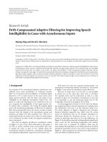
Figure 1 depicts a block diagram of this frequency-domain
N
1
N
2
n
1
n
2
X
a +
+
Y
1
Y(k)
b
+
Y
2
k
c
1
c
2
··· c
S
d
1
d
2
···
d
S
···
.
.
.
···
···
Z
1
Z
2
Z
S
Subchannel Canceller
Figure 1: Model of the subchannel (1) and the corresponding scalar
linear interference canceller (8).
model, which allows us to continue the analysis on subchan-
nel level.
3. CHANNEL PROPERTIES
Based on cable models [2, 8] and on experience from mea-
surements [4, 9], we observe that a large number of prac-
tically relevant scenarios obey the following conditions (
|·|
denotesabsolutevalue):
Assumption 1.
|a|
(α)
|c
i
|
(β)
≈|b|
(γ)
≈|d
j
|
(δ)
|n
2
|
()
≈|n
1
|, i, j ∈
{
1, , S}.
For FEXT, (α) always holds since the model for the FEXT
coupling function includes scaling by the insertion loss of the
line. For NEXT, in systems with overlapping frequency bands
for upstream and downstream, (α) does not necessarily hold
for long loops and/or high frequencies since, at least accord-
ing to the ETSI model [8], the NEXT coupling function is
not scaled by the insertion loss and is thus independent of
the loop length. Consequently, the level of the receive signal
power spectral density (PSD) on long loops may be lower
than the NEXT PSD level. Most high-bandwidth consuming
DSLs, however, employ frequency division duplexing and are
thus only vulnerable to alien NEXT, that is, NEXT from sys-
tems of different types, and “out-of-band self-NEXT,” that
is, NEXT caused by the out-of-band transmit signals of sys-
tems of the same type. Alien NEXT is often taken care of
by spectral management. Self-NEXT is usually negligible due
to out-of-band spectr al masks. The CM-related assumptions
(β)and(γ) are mainly based on measurement experience
[4, 9]. While (δ) always holds for NEXT, it may not be true
forFEXTonlongloops,wheretheFEXTPSDlevelmaylie
below the PSD level of the background noise due to the loop
attenuation. Assumption (
) states that the CM background
noise level is of the same order of magnitude as the DM back-
ground noise level.
To co nc lu de, Assumption 1 is valid for frequency division
duplexed systems as long as the pair under consideration and
the crosstalk-causing pair have roughly the same length and
are neither extremely short nor extremely long. In case the
Thomas Magesacher et al. 3
0
−10
−20
−30
−40
−50
−60
−70
−80
−90
Magnitude (dB)
510152025
Frequency (MHz)
|a|
|
b|
|
c|
|
d|
|
n
1
|=|n
2
|
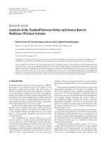
Figure 2: Channel properties a, b, c, d obtained from measure-
ments. The y-axis denotes relative magnitude in dB (the raw re-
sults are normalised by the magnitude of the largest a-value). As-
suming a V DSL transmit PSD of
−60 dBm/Hz results in a level of
−80 dB for n
1
and n
2
in order to obtain a background-noise PSD of
−140 dBm/Hz, which is the level suggested in standardisation doc-
uments [8, 10].
pairs are extremely short, the crosstalk PSD levels are very
low and consequently (β) does not hold. In case the pairs
are extremely long, both the crosstalk PSD levels and the re-
ceive signal PSD levels are very low, which may lead to nei-
ther (α)nor(β) being true. Cases with extreme lengths (short
or long) are of little practical interest, since extremely short
loops are not found in the field and extremely long loops are
out of scope for high-bandwidth consuming DSL techniques.
Care should be taken with near/far scenarios for which (α)
does not necessarily hold since the useful signal is severely
attenuated while the crosstalk is strong.
Figure 2 shows exemplary channel transfer and coupling
functions based on measurements [4]. The magnitude val-
ues are normalised by the magnitude of the largest mea-
surement result for the transfer function. Assuming a VDSL
transmit PSD of
−60 dBm/Hz and a background-noise PSD
of
−140 dBm/Hz, which is the level suggested in standardi-
sation documents [8, 10], results in a level of
−80 dB for n
1
and n
2
. Assumption 1 holds over nearly the whole frequency
range for the channel measurements depicted in Figure 2.
4. ANALYSIS
4.1. Maximum likelihood (ML) estimator
The linear Gaussian model (1) of a subchannel can be wr itten
as
Y
1
Y
2
=Y
=
a
b
=H
X + V ,(2)
where the vector V contains both noise and interference. The
covariance matrix C
v
of V is given by
C
v
=E
VV
H
=
H
v
H
H
v
, H
v
=
c
1
c
2
··· c
S
n
1
0
d
1
d
2
··· d
S
0 n
2
,
(3)
where E(
·)and·
H
denote expectation and Hermitian trans-
pose, respectively. Note that a, b, c, d, n
1
,andn
2
are complex-
valued. The ML estimator of X is defined as [11]
X =arg max
X
f (Y | X), (4)
where f (Y
|X) denotes the likelihood of X (probability den-
sity function of Y given X). For the linear Gaussian model
(2), the ML estimator can be written as [11]
X =
H
H
C
−1
v
H
−1
H
H
C
−1
v
Y . (5)
Inserting (2)and(3) into (5) fol lowed by mostly straightfor-
ward calculus yields
X = ρ
k
ML1
Y
1
+ k
ML2
Y
2
=
ρk
ML1
⎛
⎜
⎜
⎜
⎜
⎝
Y
1
+
k
ML2
k
ML1
=
k
ML
Y
2
⎞
⎟
⎟
⎟
⎟
⎠
=
Y
k
ML
(6)
with
ρ
=
1
i
d
i
2
+
n
2
2
|
a|
2
+
i
c
i
2
+
n
1
2
|
b|
2
−2Re
ab
∗
i
c
∗
i
d
i
,
k
ML1
= a
∗
i
d
i
2
+
n
2
2
−
b
∗
i
c
∗
i
d
i
,
k
ML2
= b
∗
i
c
i
2
+
n
1
2
−
a
∗
i
c
i
d
∗
i
,
(7)
where Re(
·)and·
∗
denote real part and complex conjugate,
respectively.
The ML solution (6) suggests a linear combination of Y
1
and Y
2
as estimator, which essentially corresponds to linear
interference cancellation depicted in Figure 1 and described
by
Y(k)
= Y
1
+ kY
2
. (8)
Choosing k
= k
ML
= k
ML2
/k
ML1
and applying the scaling
factor ρk
ML1
to the output of the canceller realises the ML
solution. The mutual information between X and canceller
output Y(k), when the subchannel canceller is adjusted to
the coefficient k,canbewrittenas[12]
I
X; Y(k)
= log
1+SNR(k)
,(9)
4 EURASIP Journal on Advances in Sig nal Processing
where the subchannel SNR at the canceller output is given by
SNR(k)
=
|
a + bk|
2
i
c
i
+ d
i
k
2
+
n
1
2
+
n
2
k
2
. (10)
Note that k
ML
is the interference canceller coefficient for
which the mutual information I(X; Y(k
ML
)) is maximised.
Furthermore, I(X; Y(k
ML
)) is equal to the mutual informa-
tion I(X; Y
1
, Y
2
) of the transmit signal X and the receive sig-
nal pair (Y
1
, Y
2
). In other words, the ML-based canceller pre-
serves all the infor mation contained in the two channel out-
put signals.
4.2. Steady-state performance of adaptive
cancellation
CM-aided reception can be applied in autonomous receivers
and does not require cooperation with receivers of adjacent
lines. Thus, CM-aided reception can be used to complement
or enhance level-2 or level-3 dynamic spectrum management
proposals [13], which rely on colocated receivers. Unlike in
many other applications, the ML receiver is not too complex
for implementation; however, it requires perfect knowledge
of the channel and of the statistics of noise and interference.
Since this knowledge is often not available, receiver struc-
tures that operate without any kind of side information are of
great practical importance. In the following, the suitability of
adaptive cancellation schemes based on a squared error cri-
terion is investigated. Popular examples of such schemes are
the least-mean square (LMS) and the recursive least squares
(RLS) algorithm. In a stationary environment, these algo-
rithms can be parametrised in such a way that they converge
towards the Wiener filter solution [14].
In general, the Wiener filter minimises the cost func-
tion defined as the mean of the squared error. In our setup,
this corresponds to minimising the energy of the interference
canceller’s output signal Y(k)givenby(8)withrespecttok.
The Wiener filter solution k
W
is defined by [14]
k
W
=arg min
k
E
Y(k)
2
. (11)
For our interference canceller model (8), the Wiener filter
can be expressed as (cf. Appendix A)
k
W
=−
E
Y
1
Y
∗
2
E
Y
2
Y
∗
2
. (12)
In the following, we distinguish between the Wiener filter so-
lution k
W1
obtained for X = 0 and the Wiener filter solution
k
W2
obtained for X = 0. Inserting (2)and(3) into (12), we
obtain
k
W1
=−
E
Y
1
Y
∗
2
)
E
Y
2
Y
∗
2
=−
ab
∗
+
i
c
i
d
∗
i
|b|
2
+
i
d
i
2
+
n
2
2
, (13)
which is the solution a properly parameter ised algorithm
converges to when the coefficients are a dapted while the use-
ful transmit signal is present. For X
= 0, we obtain
k
W2
= arg min
k
E
Y(k)
2
X=0
=−
E
Y
1
Y
∗
2
E
Y
2
Y
∗
2
X=0
=−
i
c
i
d
∗
i
i
d
i
2
+
n
2
2
,
(14)
which is the solution a properly parameter ised algorithm
converges to when the coefficients are adapted while there
is no useful transmit signal.
As a reference when assessing the performance of adap-
tive algorithms, we will use the mutual information between
X and Y
1
, which can be written as
I
X; Y
1
=
log
1+SNR
DM
, (15)
where the DM-subchannel SNR is given by
SNR
DM
=
|
a|
2
i
c
i
2
+
n
1
2
. (16)
4.3. Implications of Assumption 1 on the steady-state
performance of adaptive cancellation
Under Assumption 1, it can be show n that the following two
propositions hold. Instead of proofs, which are merely tech-
nical (cf. Appendix B), we provide here motivations for the
propositions, which are more insightful and simple to follow.
Proposition 1. Under the conditions defined in Assumption 1,
the following inequality holds:
I
X[m]; Y
k
W1
[m]
≤ I
X[m]; Y
1
[m]
,0≤ m ≤ M − 1.
(17)
In other words, in each subchannel, the SNR of the output
Y(k
W1
) of a linear interference canceller with tap setting k
W1
given by (13) is lower than the SNR of Y
1
.
Motivation
Since the strongest component in Y
1
stems from X, there is
a mechanism driving the canceller coefficient towards
−a/b,
which is the coefficient that eliminates X (note that
|a/b|
1). Since increasing |k| increases the residual of Z in Y(k),
there is a counter mechanism working against large values of
|k|. These two mechanisms reach an equilibrium for the so-
lution given by (13). As a net result, the power of X in Y(k
W1
)
is reduced (compared to Y
1
), which implies |k
W1
|1.
However, the larger
|k
W1
|, the higher the power of the Z-
component in Y(k
W1
). More precisely, for any k
W1
that ful-
fils
|k
W1
| > 2, the power of the Z-component in Y(k
W1
)is
higher than in Y
1
. To summarise, while the power of the X-
component is lower in Y(k
W1
) than in Y
1
, the power of the
Z-component is higher in Y(k
W1
) than in Y
1
, which confirms
Proposition 1.TheproofisgiveninAppendix B.
Thomas Magesacher et al. 5
Remark 1. In case there is no dominant interference Z,which
corresponds in our setting to c
= d = 0, adaptation while
X
= 0 yields k
W1
≈−a/b, which essentially eliminates X.
Proposition 2. Under the conditions defined in Assumption 1,
the following inequality holds:
I
X[m]; Y
k
W2
[m]
≥
I
X[m]; Y
1
[m]
,0≤ m ≤ M − 1.
(18)
In other words, in each subchannel, the SNR of the output
Y(k
W2
) of a linear interference canceller with tap setting k
W2
given by (14) is higher than the SNR of Y
1
.
Motivation
When the far-end transmitter is silent (X
= 0), the strongest
component in Y
1
stems from Z. Then, the Wiener filter so-
lution is close to
−c/d (the exact solution is given by (14)),
which essentially eliminates Z. Since
|k
W2
|≈|c/d|≈1, the
power of the N
2
-component in Y(k
W2
) remains negligible. A
lower and an upper bound on the signal energy (i.e., energy
of X) contained in Y(k
W2
)are|a|
2
−|b|
2
and |a|
2
+ |b|
2
,
respectively. Consequently, the front-end causes a negligible
reduction of signal power (
|b||a|) while essentially elimi-
nating the interference. Thus, its performance is close to that
of the ML estimator. The proof of Proposition 2 is given in
Appendix B.
Remark 2. In case there is no dominant interference Z (c
=
d = 0), adaptation with X = 0 yields k
W2
= 0, which is close
to the ML solution b
∗
|n
1
|
2
/a
∗
|n
2
|
2
.
The conclusion drawn from Propositions 1 and 2
for a typical wireline scenario (typical in the sense that
Assumption 1 is valid) with one dominant crosstalker is the
following: a canceller set to the Wiener filter solution k
W2
(i.e., when adaptation is performed while the transmitter
is silent) exhibits a higher SNR at the output compared
to the DM channel output. Moreover, the performance is
close to the ML estimator’s performance. A canceller set to
the Wiener filter solution k
W1
(i.e., when adaptation is per-
formed while the transmitter is active) exhibits a lower SNR
at the canceller output compared to the DM channel output.
Note that Propositions 1 and 2 hold for the interference-
canceller front-end (8) set to the corresponding Wiener-filter
solution. The results might not be valid for more advanced
receivers that, for example, jointly decode and estimate the
channel.
4.4. Impact of coefficient mismatch on steady-state
performance
The design of adaptive algorithms that converge to the
Wiener filter solution involves a tradeoff between conver-
gence time and mismatch. In general, the faster an adap-
tive algorithm reaches a steady solution, the larger the de-
viation from the desired Wiener filter solution becomes [14].
Hereinafter, we focus on the mismatch of a canceller adapted
while X
= 0, that is, its mismatch with respect to k
W2
.In
order to assess the sensitivity of the achieved SNR with re-
spect to the mismatch, we quantify this mismatch in terms
of the relative deviation of the coefficient’s absolute value.
A mismatch of up to 10%, for example, is expressed as
|(k − k
W2
)/k
W2
|≤0.1. We denote the set of coefficients with
amismatchofuptoμ as
K
μ
=
k :
k − k
W2
/k
W2
|≤μ
(19)
and the corresponding set of SNR values as SNR(K
μ
). The
SNR is not necessarily a rotationally symmetric function of
real part and imaginary part of k around the peak corre-
sponding to k
ML
. The sensitivity of the SNR with respect to
k depends on the channel coefficients. Figure 3 depicts two
examples: while the SNR decay is in the same order of mag-
nitude for all directions in Figure 3(a), the sensitivity of the
SNR along the direction corresponding to the imaginary part
is negligible in Figure 3(b). The coefficients in the set K
μ
lie
inside or on the marked circle
{k : |(k − k
W2
)/k
W2
|=μ}.
The worst-case SNR is obtained for one or more coefficients
on the circle. In the examples presented in the following sec-
tion, the sensitivity of the performance with respect to the
coefficient’s mismatch is quantified in terms of SNR(K
μ
).
5. SIMULATION RESULTS
In order to illustrate the implications of the propositions pre-
sented in the previous section, we evaluate the performance
of adaptive cancellation in terms of the SNR at the canceller
output given by (10). For comparison, the SNR of DM-only
processing, given by (16), and the SNR of the ML estimator
are computed. We consider M
= 8192 subchannels in the fre-
quency range from 3 kHz to 30 MHz. The coupling functions
are obtained from cable measurements [4] using the length-
adaptation methods suggested in [3].
5.1. Example 1: equal-length FEXT
We begin with a transmission scenario over a loop of length
300 m. We assume a flat transmit PSD of
−60 dBm/Hz and
flat noise PSDs of
−140 dBm/Hz at both the CM port and the
DM port of the receiver. Furthermore, there is one crosstalk
source (S
= 1) located at the same distance and transmitting
with the same PSD as the transmitter. The results for this
scenario, depicted in Figure 4, agree with the propositions
presented in the previous section. Adaptation in the absence
of the far-end signal yields a signal-to-noise ratio SNR(k
W2
)
that exceeds the signal-to-noise ratio SNR
DM
achieved by
DM-only processing for virtually the whole frequency range.
Moreover, SNR(k
W2
) is virtually the same as the upper limit
given by SNR(k
ML
). Adaptive interference cancellation elim-
inates the crosstalk almost completely. The resulting SNR is
merely limited by the background noise. Consequently, the
performance is sensitive to a mismatch of the canceller co-
efficients. A mismatch of 10% can result in a performance
degradation of up to 8 dB for sensitive subchannels. Adapta-
tion in the presence of the far-end signal, on the other hand,
yields a signal-to-noise ratio SNR(k
W1
) that is much lower
than SNR
DM
over the whole frequency range.
6 EURASIP Journal on Advances in Sig nal Processing
1.1
1.05
1
0.95
0.9
Imaginary part
0.90.95 1 1.05 1.1
Real part
0
−1
−2
−3
−4
−5
−6
(a)
1.1
1.05
1
0.95
0.9
Imaginary part
0.90.95 1 1.05 1.1
Real part
0
−1
−2
−3
−4
−5
−6
(b)
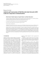
Figure 3: Normalised SNR 10 log
10
(SNR (k)/SNR (k
W2
)) in dB as a function of real part and imaginary part of k/k
W2
for two different choices
of channel coefficients a, b, c, d, n
1
, n
2
. While the SNR decay is in the same order of magnitude for all directions for case (a), the sensitivity
of the SNR along the direction corresponding to the imaginary part is negligible for case (b). Coefficientswithamismatchofupto10%,
denoted by the set K
0.1
, lie inside or on the marked circle. The plus-marker indicates k
W2
and the square-marker indicates k
ML
.
60
50
40
30
20
10
0
SNR (dB)
5 10152025
Frequency (MHz)
SNR
DM
SNR (k
W1
)
SNR (k
W2
)
SNR (k
ML
)
Figure 4: SNRs of adaptive cancellation compared to processing
only the DM signal for a transmission over a loop of 300 m length
withoneFEXTsource(S
= 1) located at the same distance and
transmitting with the same PSD of
−60 dBm/Hz as the far-end
transmitter. The background-noise level on both DM port and CM
port is
−140 dBm/Hz. The grey-shaded area indicates SNR values
for coefficient mismatch of up to 10% (SNR(K
0.1
)).
Figure 5 shows the results for a scenario with the same
parameters but with S
= 2 crosstalkers located at a distance
of 300 m from our receiver. Both crosstalk sources transmit
with the same PSD as the transmitter. On most subchannels,
SNR(k
W2
) exceeds SNR
DM
. Since the canceller tries to elim-
inate two interference sources with one coefficient, the re-
sulting SNR is smaller compared to the case of S
= 1. Thus,
also the sensitivity of the per formance with respect to coeffi-
cient mismatch is considerably lower. Adaptation of the can-
celler coefficients in the presence of the far-end signal yields
SNR (k
W1
) SNR
DM
.
Figure 6 shows the results for S
= 5FEXTsources.Al-
though the improvement of SNR(k
W2
)comparedtoSNR
DM
is marginal on most subchannels, SNR(k
W2
) is strictly larger
than SNR
DM
over the whole frequency range. Due to the
lack of degrees of freedom, the residual interference of the
5 sources is large, which also explains the insensitivity with
respect to coefficient mismatch. Adaptation of the canceller
coefficients in the presence of the far-end signal is counter-
productive, as in the previous two setups.
To conclude, adapting the canceller coefficients in the
absence of the far-end signal yields large improvements in
terms of SNR. Moreover, operating a canceller with k
W2
does not yield a l ower SNR than available at the DM out-
put. Adaptation in the presence of the far-end signal, on the
other hand, yields SNR(k
W1
) SNR
DM
and should thus be
avoided.
Typically, the benefit achieved by a canceller set to k
W1
is
large for one or very few interference sources and decays with
growing S [3]. The CM signal provides an additional degree
of freedom which allows us to cancel one interference source
to a degree that is only limited by the background noise
present on the CM input. The achievable improvement in the
presence of several interference sources depends on the cor-
relation of the resulting interference components originating
from different sources. The more similar the coupling paths
are, the smaller the overall residual interference achieved by
the canceller.
Thomas Magesacher et al. 7
60
50
40
30
20
10
0
SNR (dB)
5 10152025
Frequency (MHz)
SNR
DM
SNR (k
W1
)
SNR (k
W2
)
SNR (k
ML
)
Figure 5: SNRs of adaptive cancellation compared to processing of
DM signal only for a transmission over a loop of 300 m length with
two FEXT sources (S
= 2) located at the same distance and trans-
mitting with the same PSD of
−60 dBm/Hz as the far-end transmit-
ter. The background-noise level on both DM port and CM port is
−140 dBm/Hz. The grey-shaded area indicates SNR values for coef-
ficient mismatch of up to 50% (SNR(K
0.5
)).
5.2. Example 2: near-far scenario
Another scenario of practical relevance is depicted in
Figure 7. We investigate the upstream transmission of cus-
tomer A, who is located at a distance of 750 m from the
central office. The upstream transmission of customer A is
mainly disturbed by strong FEXT caused by the upstream
transmission of customer B, who is located at a distance of
only 250 m. This scenario represents a near-far problem of-
ten encountered in practice. Typically, there are only few cus-
tomers located at a very short distance from the central of-
fice. The number of customers located at a medium distance
is larger. Thus, we introduce customers C and D located at
a distance of 750 m from the central office. All transmitters
use a transmit PSD of
−60 dBm/Hz. A trivial solution to the
near-far problem is to reduce the t ransmit power of customer
B—an approach that is referred to as power backoff [15].
While power backoff, applied at the transmitter of customer
B, reduces the interference for customer A, it also limits the
achievable rate of customer B.
Figure 8 depicts the resulting SNRs for the near-far sce-
nario. The SNR improvement due to joint DM-CM process-
ing is marginal for subchannels below 1 MHz since there is
interference of equal strength from several sources, which
the canceller cannot eliminate. However, the gain in SNR
for subchannels above 1 MHz is large since the interference
caused by customer B is dominant. The improvement in this
frequency range is valuable since the range overlaps with
both the lower (3–5 MHz) and the upper (7–12 MHz) up-
stream band of the bandplan referred to as “997-plan,” which
60
50
40
30
20
10
0
SNR (dB)
5 10152025
Frequency (MHz)
SNR
DM
SNR (k
W1
)
SNR (k
W2
)
SNR (k
ML
)
Figure 6: SNRs of adaptive cancellation compared to processing of
DM signal only for a transmission over a loop of 300 m length with
five FEXT sources (S
= 5) located at the same distance and trans-
mitting with the same PSD of
−60 dBm/Hz as the far-end transmit-
ter. The background-noise level on both DM port and CM port is
−140 dBm/Hz. The grey-shaded area indicates SNR values for coef-
ficient mismatch of up to 100% (SNR(K
1
)).
is widely used for VDSL systems [8]. For subchannels above
7 MHz, adaptive interference cancellation enables SNR val-
ues that make transmission practically feasible, which is not
the case with DM-only processing. Adaptation of the coeffi-
cients in the presence of the far-end signal yields good results
for subchannels above 9 MHz since the interference caused
by customer B is significantly stronger than the far-end signal
at these frequencies. Assumption 1 does not hold for these
subchannels. Consequently, the observed behaviour is not
contradictory to Proposition 2.
6. CONCLUSIONS
Adaptive cancellation is a viable way to exploit common-
mode information in practical wireline systems since it does
not require channel knowledge. A thorough performance
analysis of adaptive cancellation has been presented. It was
shown that adaptation of the canceller coefficients in the
absence of the useful far-end signal yields an improvement
in terms of throughput for a large class of practical sce-
narios. More importantly, adaptation in the presence of the
far-end signal decreases the throughput and should thus be
avoided.
The proposed subchannel interference canceller lends it-
self to a straightforward implementation in multicarrier-
based wireline receivers. The scalar cancellers operating on
subchannels can be activated individually based on the chan-
nel condition, which allows for simple adaptation and en-
hances robustness in case of suddenly appearing disturbers.
8 EURASIP Journal on Advances in Sig nal Processing
Customer
A
X
C
Z
2
D
Z
3
Customer
B
Z
1
Central
office
Y
1
Y
2
250 m
750 m
Figure 7: Near-far scenario: the upstream transmission of customer A is disturbed by strong FEXT from customer B, who is located closely
to the central o ffice, and by weaker FEXT from customers C and D. All FEXT sources transmit with the same PSD of
−60 dBm/Hz as the
far-end transmitter of customer A. The background-noise level on both DM port and CM port is
−140 dBm/Hz.
60
50
40
30
20
10
0
SNR (dB)
13579111315
Frequency (MHz)
SNR
DM
SNR (k
W1
)
SNR (k
W2
)
SNR (k
ML
)
Figure 8: SNRs for near-far scenario. The improvement in terms
of SNR for subchannels above 1 MHz is significant. For frequencies
above 7 MHz, adaptive interference cancellation yields SNR values
that make transmission on these subchannel sensible, which would
not be possible by processing the DM signal only. The grey-shaded
area indicates SNR values for coefficientmismatchofupto10%
(SNR(K
0.1
)).
APPENDICES
A. WIENER FILTER SOLUTION (12) FOR THE MODEL (8)
Inserting (8) into (11) yields
k
W
= arg min
k
E
Y(k)
2
=
arg min
k
kE
Y
∗
1
Y
2
+ k
∗
E
Y
1
Y
∗
2
+ |k|
2
E
Y
2
Y
∗
2
.
(A.1)
In order to find the extremum, we set the first derivative with
respect to k to zero:
d
dk
W
k
W
E
Y
∗
1
Y
2
+ k
∗
W
E
Y
1
Y
∗
2
+
k
W
2
E
Y
2
Y
∗
2
!
=0.
(A.2)
Keeping in mind that (d/dk)k
∗
= 0and(d/dk)|k|
2
= k
∗
,we
obtain
E
Y
∗
1
Y
2
+ k
∗
W
E
Y
2
Y
∗
2
=
0, (A.3)
which yields expression (12) for the Wiener filter solution in
the model (8).
B. PROOF OF PROPOSITIONS 1 AND 2
Since validity of Assumption 1 is a prerequisite for Proposi-
tions 1 and 2, we begin with formalising the relations
and
≈. We consider that |v||w| holds if
|v|
|w|
≥
η (B.1)
for a given “large” η. A sensible choice may be η
= 10, which
corresponds to a magnitude ratio of 20 dB.
We consider that
|v|≈|w| holds if
1
χ
≤
|
v|
|w|
≤
χ (B.2)
for a given “small” χ
≥ 1. A sensible choice may be χ =
2, which corresponds to magnitude ratios in the range of
±6 dB. Hereinafter, we require that
1
≤ χ<
√
η
2
,(B.3)
which implies that η>4 and holds for all sensible choices of χ
and η. Note that it is sufficient to prove the relations between
the SNRs given by (10)and(16), since the mutual informa-
tion (9) is a monotonic function of the SNR. In the proofs
Thomas Magesacher et al. 9
presented in the sequel, it is assumed that S = 1. The exten-
sion for S>1,whichisstraightforwardbutcumbersome,
does not yield any additional insight and it is thus omitted.
Proof of Proposition 1. We need to prove that SNR(k
W1
) ≤
SNR
DM
, that is,
a + bk
W1
2
c + dk
W1
2
+
n
1
2
+
n
2
k
W1
2
≤
|
a|
2
|c|
2
+
n
1
2
. (B.4)
The proof is laid out in three steps. First, we show that the sig-
nal power with interference cancellation using k
W1
,givenby
|a + bk
W1
|
2
(cf. (10)), is smaller than the signal power with
DM-only reception, given by
|a|
2
(cf. (16)), that is,
a + bk
W1
< |a|. (B.5)
Second, we show that the resulting interference power of an
interference canceller with k
W1
,givenby|c + dk
W1
|
2
,islarger
than the interference power with DM-only reception, given
by
|c|
2
, that is,
c + dk
W1
> |c|. (B.6)
Third, we note that
|n
1
|
2
+ |n
2
k
W1
|
2
≥|n
1
|
2
, that is, that
the resulting noise power with interference cancellation us-
ing k
W1
is larger than with DM-only reception.
Step 1. We start from the inequality
χ
≤
η,(B.7)
which follows directly from (B.3). Using Assumption 1 and
definitions (B.1)and(B.2), inequality (B.7) yields
|c|
|b|
|
d|
|b|
≤
χ
2
≤ η ≤
|
a|
|b|
,
bcd
∗
|b|
3
≤
|
a||b|
2
|b|
3
,
bcd
∗
≤|
a||b|
2
,
a
|d|
2
+
n
2
2
+
bcd
∗
|b|
2
+ |d|
2
+
n
2
2
≤|a|.
(B.8)
The left-hand side of (B.8)canbelowerboundedby
a
|
d|
2
+
n
2
2
+
bcd
∗
|b|
2
+ |d|
2
+
n
2
2
≥
a
|
d|
2
+
n
2
2
−
bcd
∗
|b|
2
+ |d|
2
+
n
2
2
=
a + bk
W1
,
(B.9)
where inequality and equality follow from the t riangular in-
equality and (13), respectively. Combining (B.8)and(B.9)
yields (B.5).
Step 2. It is straightforward to show that when (B.3)holds,
the following inequalit y also holds:
1
≥
2
ηχ
2
1+
1
η
2
+
1
χ
4
η
. (B.10)
Using Assumption 1 and definitions (B.1)and(B.2), inequal-
ity (B.10) yields
|a||d|
|b|
2
≥ ηχ ≥
2
χ
1+
1
η
2
+
1
χ
3
≥ 2
|c|
|b|
1+
n
2
2
|b|
2
+
|c|
|b|
|
d|
2
|b|
2
,
|a||d|
|b|
2
≥
2|c|
|b|
2
+
n
2
2
|b|
3
+
|c||d|
2
|b|
3
,
|a||b||d|−|c|
|b|
2
+
n
2
2
≥|
c|
|b|
2
+ |d|
2
+
n
2
2
,
|a||b||d|−|c|
|b|
2
+
n
2
2
|b|
2
+ |d|
2
+
n
2
2
≥|c|.
(B.11)
The left-hand side of (B.11) can be upper-bounded by
|a||b||d|−|c|
|b|
2
+
n
2
2
|b|
2
+ |d|
2
+
n
2
2
≤
c
|b|
2
+
n
2
2
− ab
∗
d
|b|
2
+ |d|
2
+
n
2
2
=
c + dk
W1
,
(B.12)
where inequality and equality follow from the triangular in-
equality and (13), respectively. Combining (B.11)and(B.12)
yields (B.6), which concludes the proof.
Proof of Proposition 2. We need to prove that SNR(k
W2
) ≥
SNR
DM
, that is,
a + bk
W2
2
c + dk
W2
2
+
n
1
2
+
n
2
k
W2
2
≥
|
a|
2
|c|
2
+
n
1
2
. (B.13)
An upper bound for
|k
W2
|, which follows directly from (B.2),
is given by
k
W2
=
|
c||d|
|d|
2
+
n
2
2
<
|c||d|
|d|
2
≤ χ. (B.14)
It is straightforward to show that w hen (B.3) holds, the fol-
lowing inequality also holds:
η
2
1 − 2
χ
η
−
1
1+η
2
2
−
2
χ
η
− χ
4
≤ 0. (B.15)
Using Assumption 1 and (B.1), we obtain from (B.15)
|c|
2
n
1
2
1 − 2
χ
η
−
1
1+η
2
2
−
2
χ
η
− χ
4
≤ 0,
|c|
2
1 − 2
χ
η
+
n
1
2
1 − 2
χ
η
≤
|
c|
2
1+η
2
2
+
n
1
2
1+χ
4
,
|a|
2
1 − 2(χ/η)
|c|
2
/
1+η
2
2
+
n
1
2
1+χ
4
≤
|
a|
2
|c|
2
+
n
1
2
.
(B.16)
10 EURASIP Journal on Advances in Sig nal Processing
The left-hand side of (B.16) can be upper-bounded by
|a|
2
1 − 2(χ/η)
|c|
2
/
1+η
2
2
+
n
1
2
1+χ
4
≤
|
a|
2
1−2
|
b|
k
W2
/|a|
|c|
2
1+|d|
2
/
n
2
2
−2
+
n
1
2
1+
n
2
2
k
W2
2
/
n
1
2
)
≤
a+bk
W2
2
|c|
2
1+|d|
2
/
n
2
2
)
−2
+
n
1
2
1+
n
2
2
k
W2
2
/
n
1
2
)
=
a + bk
W2
2
c + dk
W2
2
+
n
1
2
+
n
2
k
W2
2
.
(B.17)
The first inequality follows from the bound (B.14),
Assumption 1, and definitions (B.1)and(B.2). The second
inequality follows from the triangular inequality and the
equality follows from (14). Combining (B.16)and(B.17)
yields (B.13), which concludes the proof.
ACKNOWLEDGMENTS
This work was supported by the European Commission
and by the Swedish Agency for Innovation Systems, VIN-
NOVA, through the IST-MUSE and the Eureka-Celtic BAN-
ITS projects, respectively.
REFERENCES
[1] A. G. Bell, “Improvement in telegraphy,” Letters Patent no.
174,465, dated March, application filed February, 1876.
[2] W.Y.Chen,DSL: Simulation Techniques and Standards Devel-
opment for Digital Subscriber Line Systems, Macmillan Techni-
cal, Indianapolis, Ind, USA, 1998.
[3] T. Magesacher, P.
¨
Odling,P.O.B
¨
orjesson, and S. Shamai, “In-
formation rate bounds in common-mode aided wireline com-
munications,” European Transactions on Telecommunications,
vol. 17, no. 5, pp. 533–545, 2006.
[4] T. Magesacher, P.
¨
Odling,P.O.B
¨
orjesson, et al., “On the ca-
pacity of the copper cable channel using the common mode,”
in Proceedings of IEEE Global Telecommunications Conference
(GLOBECOM ’02), vol. 2, pp. 1269–1273, Taipei, Taiwan,
November 2002.
[5] T. Magesacher, P.
¨
Odling, and P. O. B
¨
orjesson, “Adaptive in-
terference cancellation using common-mode information in
DSL,” in Proceedings of the 13th European Signal Processing
Conference (EUSIPCO ’05), Antalya, Turkey, September 2005.
[6]T.H.Yeap,D.K.Fenton,andP.D.Lefebvre,“Anovel
common-mode noise cancellation technique for VDSL appli-
cations,” IEEE Transactions on Instrumentation and Measure-
ment, vol. 52, no. 4, pp. 1325–1334, 2003.
[7] A. H. Kamkar-Parsi, M. Bouchard, G. Bessens, and T. H. Yeap,
“A wideband crosstalk canceller for xDSL using common-
mode information,” IEEE Transactions on Communications,
vol. 53, no. 2, pp. 238–242, 2005.
[8] ETSI TM6, “Transmission and multiplexing (TM); access
transmission systems on metallic access cables; very high speed
digital subscriber line (VDSL)—Part 1: functional require-
ments,” TS 101 270-1, Version 1.1.6, August 1999.
[9] T. Magesacher, W. Henkel, G. Taub
¨
ock, and T. Nordstr
¨
om,
“Cable measurements supporting xDSL technologies,” Journal
e&i Elektrotechnik und Informationstechnik, vol. 199, no. 2, pp.
37–43, 2002.
[10] ANSI T1E1.4, “Very-high-bit-rate digital subscriber line
(VDSL) metallic interface—part 1: functional requirement
and common specification,” T1E1.4/2000-009R3,February
2001.
[11] S. M. Kay, Fundamentals of Statistical Signal Processing: Esti-
mation Theory, Prentice-Hall, Upper Saddle River, NJ, USA,
1993.
[12] T. M. Cover and J. A. Thomas, Elements of Information Theory,
John Wiley & Sons, New York, NY, USA, 1991.
[13] K. B. Song, S. T. Chung, G. Ginis, and J. M. Cioffi,“Dy-
namic spectrum management for next-generation DSL sys-
tems,” IEEE Communications Magazine, vol. 40, no. 10, pp.
101–109, 2002.
[14] S. Haykin, Adaptive Filter Theory, Prentice-Hall, Upper Saddle
River, NJ, USA, 3rd edition, 1996.
[15] S. Schelstraete, “Defining upstream power backoff for VDSL,”
IEEE Journal on Selected Areas in Communications, vol. 20,
no. 5, pp. 1064–1074, 2002.
Thomas Magesacher received the Dipl Ing. and Ph.D. degrees in
electrical eng ineering from Graz University of Technology, Austria,
in 1998 and Lund University, Sweden, in 2006, respectively. From
1997–2003, he was with Infineon Technologies (former Siemens
Semiconductor) and with the Telecommunications Research Cen-
ter Vienna (FTW), Austria, working on circuit design and concept
engineering for communication systems. Since February 2003, he
has been with Lund University, Sweden. His responsibilities include
the management of national and European research projects and
research cooperations with industry as well as undergraduate ed-
ucation. In 2006, he received a grant from the Swedish Research
Council for a postdoctoral fellowship at the Department of Electri-
cal Engineering, Stanford University, USA. His research interests
include adaptive and mixed-signal processing, communications,
and applied information theory.
Per
¨
Odling was born in 1966 in
¨
Ornsk
¨
oldsvik, Sweden. He received
an M.S.E.E. degree in 1989, a Licentiate of Engineering degree 1993,
and a Ph.D. degree in signal processing 1995, all from Lule
˚
a Uni-
versity of Technology, Sweden. In 2000, he was awarded the Do-
cent degree from Lund Institute of Technology, and in 2003 he was
appointed Professor there. From 1995, he was an Assistant Pro-
fessor at Lule
˚
a University of Technology, serving as Vice Head of
the Division of Sig nal Processing. In parallel, he consulted for Telia
AB and ST-Microelectronics, developing an OFDM-based proposal
for the standardisation of UMTS/IMT-2000 and VDSL for stan-
dardisation in ITU, ETSI, and ANSI. Accepting a position as Key
Researcher at the Telecommunications Research Center Vienna in
1999, he left the arctic north for historic Vienna. There, he spent
three years advising graduate students and industry. He also con-
sulted for the Austrian Telecommunications Regulatory Authority
on the unbundling of the local loop. He is, since 2003, a Professor
at Lund Institute of Technology, stationed at Ericsson AB, Stock-
holm. He also serves as an Associate Editor for the IEEE Transac-
tions on Vehicular Technology. He has published more than forty
journal and conference papers, thirty-five standardisation contri-
butions, and a dozen patents.
Per Ola B
¨
orjesson was born in Karlshamn, Sweden in 1945. He
received his M.S. deg ree in electrical engineering in 1970 and his
Ph.D. degree in telecommunication theory in 1980, both from
Lund Institute of Technology (LTH), Lund, Sweden. In 1983, he
Thomas Magesacher et al. 11
the degree of Docent in Telecommunication Theor y. Between 1988
and 1998, he was Professor of Signal Processing at Lule
˚
aUniver-
sity of Technology. Since 1998, he is a Professor of Signal Process-
ing at Lund University. His primary research interest lies in high-
performance communication systems, in particular, high-data-rate
wireless and twisted pair systems. He is presently researching signal
processing techniques in communication systems that use orthog-
onal frequency-division multiplexing (OFDM) or discrete multi-
tone modulation (DMT). He emphasises the interaction between
models and real systems, from the creation of application-oriented
models based on system knowledge to the implementation and
evaluation of algorithms.