Báo cáo hóa học: " Research Article NLOS Identification and Weighted Least-Squares Localization for UWB Systems Using Multipath Channel Statistics" potx
Bạn đang xem bản rút gọn của tài liệu. Xem và tải ngay bản đầy đủ của tài liệu tại đây (1.08 MB, 14 trang )
Hindawi Publishing Corporation
EURASIP Journal on Advances in Signal Processing
Volume 2008, Article ID 271984, 14 pages
doi:10.1155/2008/271984
Research Article
NLOS Identification and Weighted Least-Squares Localization
for UWB Systems Using Multipath Channel Statistics
˙
Ismail G
¨
uvenc¸, Chia-Chin Chong, Fujio Watanabe, and Hiroshi Inamura
DoCoMo Communications Laboratories USA, Inc., 3240 Hillvie w Avenue, Palo Alto, CA 94304, USA
Correspondence should be addressed to
˙
Ismail G
¨
uvenc¸,
Received 30 March 2007; Revised 6 July 2007; Accepted 21 July 2007
Recommended by Richard J. Barton
Non-line-of-sight (NLOS) identification and mitigation carry significant importance in wireless localization systems. In this paper,
we propose a novel NLOS identification technique based on the multipath channel statistics such as the kurtosis, the mean excess
delay spread, and the root-mean-square delay spread. In particular, the IEEE 802.15.4a ultrawideband channel models are used as
examples and the above statistics are found to be well modeled by log-normal random variables. Subsequently, a joint likelihood
ratio test is developed for line-of-sight (LOS) or NLOS identification. Three different weighted least-squares (WLSs) localization
techniques that exploit the statistics of multipath components (MPCs) are analyzed. The basic idea behind the proposed WLS
approaches is that smaller weights are given to the measurements which are likely to be biased (based on the MPC information),
as opposed to variance-based WLS techniques in the literature. Accuracy gains with respect to the conventional least-squares
algorithm are demonstrated via Monte-Carlo simulations and verified by theoretical derivations.
Copyright © 2008
˙
Ismail G
¨
uvenc¸ et al. This is an open access article distributed under the Creative Commons Attribution License,
which permits unrestricted use, distribution, and reproduction in any medium, provided the original work is properly cited.
1. INTRODUCTION
The location of a mobile terminal (MT) can be estimated
using different parameters of a received signal, such as the
time-of-arrival (TOA), angle-of-arrival (AOA), and/or the
received signal strength (RSS). Ultrawideband (UWB) ra-
dio has a great potential for accurate ranging and localiza-
tion systems due to its very wide bandwidth and capability
in resolving individual multipath components (MPCs) [1–
7]. Therefore, the TOA of the received signal can be esti-
mated with high accuracy for UWB systems if the first ar-
riving path has been identified precisely [8–11]. One of the
major challenges for localization systems is the mitigation
of non-line-of-sight (NLOS) effects. If the direct path be-
tween a fixed terminal (FT) (An FT is usually a base sta-
tion in a cellular network or an anchor node in a sensor
network.) and the MT is being obstructed, the TOA of the
signal to the FT will be delayed, which introduces a pos-
itive bias. Using such NLOS TOA estimates during the lo-
calization of the MT position may significantly degrade the
positioning accuracy. Hence, FTs that are under the NLOS
condition have to be identified and their effects have to be
mitigated.
The NLOS identification and mitigation techniques have
been discussed extensively in the literature, but mainly
within the cellular network framework [12–14]. For exam-
ple, in [12], the standard deviation of the range measure-
ments are compared with the threshold for NLOS identifi-
cation, where the measurement noise variance is assumed to
be known. In [13], a decision-theoretic NLOS identification
framework is presented, where various hypothesis tests are
developed for known and unknown probability density func-
tions (PDFs) of the TOA measurements. A nonparametric
NLOS identification approach is discussed in [14, 15], where
a suitable distance metric is used between the known mea-
surement error distribution and the nonparametrically esti-
mated distance measurement distribution in order to deter-
mine if a given FT is line-of-sight (LOS) or NLOS. Note that
such techniques usually assume that the MT is moving and
the number/density of obstructions between the MT and the
FT vary. This implies that the bias for the NLOS range mea-
surements change over time and have larger variances. On
the other hand, when the MT is static, the variance of the
NLOS range measurements may not show as much deviation
from the variance of the LOS range measurements [16]. In
such situations, the multipath characteristics of the received
2 EURASIP Journal on Advances in Signal Processing
signal may provide some insight regarding the LOS/NLOS
identification. For example, in [17], the NLOS identification
for UWB systems was briefly addressed by comparing the
normalized strongest path with a fixed threshold. However,
for such a scheme, optimal selection of certain parameters
such as the threshold and the time interval are essential.
As an alternative to identify the NLOS scenarios from the
received multipath signal, it is also possible to use the infor-
mation from the overall mobile network for NLOS mitiga-
tion, provided that there are sufficient number of LOS FTs.
For example, in [18], a residual-based algorithm was pro-
posed for NLOS mitigation by assuming that the number of
available FTs are more than three.
1
Different combinations
of FTs with at least three FTs in each combination are con-
sidered in order to evaluate the MT location and the corre-
sponding residual error. The location estimates with smaller
residuals have larger chances of corresponding to the correct
MT location. Hence, the proposed technique weights differ-
ent location estimates with the inverses of their residual er-
rors. Some other NLOS mitigation techniques using the mo-
bile network are reported in [19–27].
The objectives of this paper are three-fold. First, to model
and characterize the amplitude and delay statistics of IEEE
802.15.4a channels. Second, to propose NLOS identification
techniques based on the amplitude and delay statistics of
the UWB channels. The amplitude statistics are captured us-
ing the kurtosis, and the delay statistics are evaluated using
the mean excess delay and the root mean square (rms) de-
lay spread of the received MPCs. And third, to analyze dif-
ferent weighted least-squares (WLS) localization techniques
and evaluate their performance via Monte-Carlo simulations
using the IEEE 802.15.4a channel model. The paper is orga-
nized as follows. In Section 2, the UWB channel model and
associated channel statistics to be used in NLOS identifica-
tion are outlined, and the localization system model is briefly
reviewed. Section 3 introduces three different NLOS identi-
fication techniques based the statistics of the MPCs, while
Section 4 introduces three different WLS localization tech-
niques. Simulation results are presented in Section 5 and fi-
nally Section 6 provides some concluding remarks.
2. CHANNEL AND SYSTEM MODELS
2.1. Multipath channel statistics
Let the channel impulse response (CIR) of the received signal
be represented as
h(t)
=
L
l=1
α
l
δ
t −τ
l
,(1)
where L is the total number of MPCs, and α
l
and τ
l
are the
amplitude and delay of the lth MPC, respectively. The TOA
of the received signal is given by τ
toa
= τ
1
, which is identified
1
When all the FTs are LOS, three FTs are sufficient for two-dimensional
(2D) localization, and four FTs are sufficient for 3D localization.
by the first arriving path. If τ
1
can be accurately estimated,
the true distance d between the FT and the MT can be easily
calculated for LOS scenarios. However, for NLOS scenarios,
the distance estimate may typically include a positive NLOS
bias. There may be two major reasons for the existence of
such a bias: while the first path may be completely blocked
and cannot be detected at the receiver, it may also be the case
that it is being delayed due to experiencing a different prop-
agation speed through the obstacles [28, 29]. For the second
scenario, the delay of the first arriving path may be negligible
for certain NLOS channels, which implies close to zero bias.
In this paper, we assume that NLOS channels introduce con-
siderable bias to the first arriving path. In other words, we
have
H
0
: d = cτ
1
,
H
1
: d<cτ
1
,
(2)
where c denotes the speed of light, H
0
is the LOS hypothesis,
and H
1
is the NLOS hypothesis. Hence, for NLOS situations,
even if the first arriving path is correctly identified, the es-
timated distance is larger than the actual distance between
the FT and the MT due to the always present positive bias.
Therefore, if NLOS FTs are used in localization, they will de-
grade the localization accuracy, and it is essential to identify
the NLOS FTs and mitigate their effects for accurate localiza-
tion.
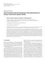
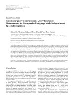
TheimpactofNLOSbiasmaybedifferent for a mov-
ing MT and a stationary MT as illustrated in Figure 1. As the
MT-1 moves through the network, the LOS and NLOS con-
dition changes intermittently. For example, at t
1
,MT-1isun-
der LOS condition with FT
1
,FT
4
,andFT
5
while it is under
NLOS condition with other FTs. Similarly, at other time in-
stants MT-1 will be under LOS and NLOS with some other
FTs. As the MT-1 moves through the network, the intensity
of obstacles for a NLOS FT will change which will effectively
varytheNLOSbias.Hence,foramovingMT,thevarianceof
the distance estimate to a NLOS FT will be larger due to the
changes in the NLOS bias. On the other hand, for a station-
ary MT such as the MT-2, the NLOS bias is fixed over time
as opposed to a moving MT. Hence, observing the variance
of distance estimates may not provide sufficient information
whether a stationary MT is under LOS or NLOS condition.
Moreover, for indoor scenarios, the MT may move signifi-
cantly prior to detecting if it is under LOS or NLOS scenario,
and hence, a NLOS mitigation/localization based on the vari-
ance of the distance estimate may become quite complicated.
In this paper, we distinguish between the LOS or NLOS
scenarios by exploiting the statistics of the received MPCs.
The kurtosis, the mean excess delay, and the rms delay spread
are used in order to capture the amplitude and delay statistics
for the LOS and NLOS scenarios, respectively. The kurtosis of
a certain data is defined as the ratio of the fourth-order mo-
ment of the data to the square of the second-order moment
(i.e., the variance) of the data. As stated in [30], the “kurtosis
characterizes how peaky” a sample data. Thus, it may be used
as a tool to characterize the level of LOS condition of a cer-
tain channel. This implies that for a CIR with high kurtosis
values, it is more likely that the received signal is under LOS
˙
Ismail G
¨
uvenc¸etal. 3
FT-1
FT-2 FT-3
FT-4
FT-5
FT-6
MT-1
MT-2
t
1
t
2
t
3
Figure 1: A simple scenario where there are six FTs (denoted with
stars) and two MTs (denoted with circles). The environment is oc-
cupied with some obstructions (e.g., buildings, foliage, etc.). The
MT-1 moves through the network while the MT-2 is stationary.
scenario. Given a certain channel realization h(t), kurtosis of
|h(t)| can be calculated as [30]
κ
=
E
h(t)
−
μ
|h|
4
E
h(t)
−
μ
|h|
2
2
=
E
h(t)
−
μ
|h|
4
σ
4
|h|
,(3)
where μ
|h|
and σ
|h|
are the mean and standard deviation of
the
|h(t)|,respectively.
While the kurtosis provides information about the am-
plitude statistics of the received MPCs, it does not provide
any information regarding the delay properties of the re-
ceived MPCs. Two important statistics that characterize the
delay information of the multipath channel are the mean ex-
cess delay τ
m
and the rms delay spread τ
rms
,whicharegiven
by [31]
τ
m
=
∞
−∞
t
h(t)
2
dt
∞
−∞
h(t)
2
dt
,
τ
rms
=
∞
−∞
t −τ
m
2
h(t)
2
dt
∞
−∞
h(t)
2
dt
.
(4)
2.2. Localization system model
For the localization system model, we consider a wireless net-
work where there are N FTs,
x = [x y]
T
is the estimate of the
MT location, x
i
= [x
i
y
i
]
T
is the position of the ith FT,
d
i
is
the measured distance between the MT and the ith FT com-
monly modeled as
d
i
= d
i
+ b
i
+ n
i
= cτ
i
, i = 1, 2, , N,
(5)
where τ
i
is the TOA of the signal at the ith FT, d
i
is the actual
distance between the MT and the ith FT, n
i
∼N (0, σ
2
i
) is the
additive white Gaussian noise (AWGN) with variance σ
2
i
,and
b
i
is a positive distance bias introduced due to LOS blockage,
given by
b
i
=
0ifith FT is LOS,
ψ
i
if ith FT is NLOS.
(6)
For NLOS FTs, the bias term ψ
i
was modeled in differ-
ent ways in the literature such as exponentially distributed
[18, 32], uniformly distributed [27, 33], Gaussian distributed
[34], constant along a time window [21], or based on an
empirical model from measurements [29, 35]. Typically, the
model depends on the wireless propagation channel and the
specific technology under consideration (e.g., cellular net-
works, wireless sensor networks, etc.). In this paper, we will
model the term b
i
as an exponentially distributed random
variable with mean λ
i
based on [18, 32].
Once all the distance estimates in (5) are available, the
noisy measurements and NLOS bias at different FTs yield cir-
cles which do not intersect at the same point, resulting in the
following inconsistent equations:
x − x
i
2
+
y − y
i
2
=
d
2
i
, i = 1, 2, , N.
(7)
3. LOS/NLOS IDENTIFICATION
3.1. Kurtosis of the multipath channel
The PDF of the kurtosis of the multipath channel κ can be
obtained for both LOS and NLOS scenarios using sample
channel realizations from both scenarios. Here, we used sam-
ple channel realizations of the IEEE 802.15.4a standard chan-
nel models in order to obtain the histograms of κ for eight
different channel models (i.e., CM1 through CM8) as defined
in [7]. It is found that the histograms can be well modeled by
a log-normal distribution given as follows:
p(κ)
=
1
κ
√
2πσ
κ
exp
−
In(κ) −μ
κ
2
2σ
2
κ
,(8)
where μ
κ
is the mean and σ
κ
is the standard deviation of
In(κ). The corresponding parameters for the eight different
channel models are tabulated in Tab l e 1. We also used the
Kolmogorov-Smirnov (K-S) goodness-of-fit hypothesis test
at 5% significance level to analyze how well the log-normal
PDF characterizes the data. Ta bl e 1 also shows the passing
rates of the K-S test for all the channel models. From the ta-
ble, it shows that the log-normal distribution fits well to the
kurtosis of the data for all channel models with more than
90% of passing rates.
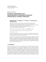
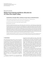
The log-normal PDFs of the kurtosis for the eight chan-
nel models are depicted in Figure 2. It can be seen that for in-
door residential, indoor office, and industrial environments,
kurtosis can provide good information regarding if the re-
ceived signal is LOS or NLOS. However, for outdoor environ-
ment, the PDFs are not distinct, and interestingly, the mean
of the NLOS case is larger then the mean of the LOS case. A
possible reason why the amplitude statistics is insufficient to
identify the LOS/NLOS scenarios might be due to the highly
dispersive characteristics of the outdoor environments [7].
Therefore, in order to have a more robust identifier, the de-
lay statistics must be taken into consideration as will be dis-
cussed in the next section.
4 EURASIP Journal on Advances in Signal Processing
Table 1: The mean and the standard deviation of the log-normal PDF for the kurtosis of the IEEE 802.15.4a channels.
Channel model μ
κ
σ
κ
K-S
κ
CM1 (residential LOS) 4.6631 0.5770 95.4%
CM2 (residential NLOS) 3.6697 0.4886 94.6%
CM3 (indoor office LOS) 4.4744 0.4579 95.7%
CM4 (indoor office NLOS) 2.8154 0.3459 95.5%
CM5 (outdoor LOS) 4.4509 0.5163 95.5%
CM6 (outdoor NLOS) 4.8886 0.4497 95.5%
CM7 (industrial LOS) 4.2637 0.7447 95.6%
CM8 (industrial NLOS) 2.1141 0.1487 95.4%
5004003002001000
Kurtosis
0
0.005
0.01
0.015
0.02
0.025
CM1
CM2
(a)
3002001000
Kurtosis
0
0.02
0.04
0.06
0.08
CM3
CM4
(b)
5004003002001000
Kurtosis
0
0.002
0.004
0.006
0.008
0.01
CM5
CM6
(c)
3002001000
Kurtosis
0
0.1
0.2
0.3
CM7
CM8
(d)
Figure 2: Log-normal PDFs of the kurtosis for CM1 to CM8 of the IEEE 802.15.4a channel models.
3.2. Mean excess delay and rms delay spread of
the multipath channel
Similar to the kurtosis analysis as discussed in the previous
section, we obtained the histograms of the mean excess delay
and rms delay spread for eight different channel models from
the IEEE 802.15.4a channels. We also found that the log-
normal distribution fits to the histograms well. This obser-
vation was further verified using the K-S hypothesis test with
5% of significance level. The mean and standard deviation of
In(τ
m
)andIn(τ
rms
)aswellastheK-Spassingratesaretab-
ulated in Tab le 2, and their corresponding PDFs are depicted
˙
Ismail G
¨
uvenc¸etal. 5
in Figures 3 and 4. We observe that as opposed to residential
and indoor-office environments, the LOS and NLOS PDFs
in outdoor and industrial environments are quite distinct,
which implies reliability of the LOS/NLOS identification.
3.3. Likelihood-ratio test
If the a priori knowledge of the statistics of κ, τ
m
,andτ
rms
are available under the LOS and NLOS scenarios in a cer-
tain environment, likelihood ratio tests can be performed
for hypothesis selection. Let P
kurt
los
(κ), P
kurt
nlos
(κ), P
med
los
(τ
m
),
P
med
nlos
(τ
m
), P
rms−ds
los
(τ
rms
), and P
rms−ds
nlos
(τ
rms
) be the PDFs of the
kurtosis, the mean excess delay spread, and the rms delay
spread corresponding to LOS and NLOS conditions, respec-
tively. Then, given a channel realization h(t), we may con-
sider the following three likelihood ratio tests for LOS/NLOS
identification of h(t):
(1) kurtosis test:
P
kurt
los
(κ)
P
kurt
nlos
(κ)
H
0
≷
H
1
1, (9)
(2) mean excess delay test:
P
med
los
τ
m
P
med
nlos
τ
m
H
0
≷
H
1
1, (10)
(3) rms delay spread test:
P
rms−ds
los
τ
rms
P
rms−ds
nlos
τ
rms
H
0
≷
H
1
1, (11)
where, if the likelihood ratio is larger than 1, we choose the
LOS hypothesis (H
0
), and if otherwise, we choose the NLOS
hypothesis (H
1
).
Rather than using only the PDFs of individual parame-
ters, a better approach would be to consider the joint PDF of
these parameters, which will yield
P
joint
los
κ, τ
m
, τ
rms
P
joint
nlos
κ, τ
m
, τ
rms
H
0
≷
H
1
1. (12)
Since in practice it is very difficult to obtain the joint PDFs
as given in (12), a suboptimal approach is proposed by con-
sidering κ, τ
m
,andτ
rms
as independent to each other. Note
that in practice, there is some correlation between these ran-
dom variables, and independence assumption will not usu-
ally hold. In order to assess the amount of correlation be-
tween these random variables, we calculated the correlation
coefficients
2
between the pairs of random variables as tabu-
lated in Tab le 3 for 1000 channel realizations from each of the
IEEE 802.15.4a channel models. We also obtained the cor-
relation coefficient between the strongest path (SP) energy
2
Correlation coefficient between two random variables R
1
and R
2
is given
by ρ
R
1
,R
2
= (E(R
1
R
2
) −E(R
1
)E(R
2
))/σ
R
1
σ
R
2
,whereσ
R1
and σ
R2
are the
standard deviations of R
1
and R
2
,respectively.
(normalized with the total received energy) and each of the
κ, τ
m
,andτ
rms
for comparison purposes. While the corre-
lation coefficients are usually low for most channel models,
relatively larger values of ρ
τ
m
,τ
rms
and ρ
sp,κ
for certain chan-
nel models are noticeable. Results in Tab le 3 imply that while
there is some correlation between some of these parame-
ters, a suboptimal detector that considers these parameters
independently may still improve the NLOS detection perfor-
mance since the correlation tends to be smaller than 0.5 for
most of the channel models. Then, (12) can be simplified to
J
κ, τ
m
, τ
rms
H
0
≷
H
1
1, (13)
where
J
κ, τ
m
, τ
rms
=
P
kurt
los
(κ)
P
kurt
nlos
(κ)
×
P
med
los
τ
m
P
med
nlos
τ
m
×
P
rms−ds
los
τ
rms
P
rms−ds
nlos
τ
rms
.
(14)
The histogram of the logarithm of J(κ, τ
m
, τ
rms
) is depicted
in Figure 5(a) for CM3 and CM4 of the IEEE 802.15.4a
channels, and Figure 5(b) shows the histogram of log
10
(1 +
J(κ, τ
m
, τ
rms
)). While J(κ, τ
m
, τ
rms
)canbeusedtomakea
hard decision to decide if a received signal is LOS or NLOS, it
may also be used as a soft information in the WLS algorithm
as will be discussed in the next section.
4. WLS LOCALIZATION TECHNIQUES
The NLOS information as discussed in the previous section
can be used in numerous ways to improve the localization
accuracy. In this section, we will present different WLS tech-
niques in order to mitigate the NLOS effects. By considering
the localization model presented in Section 2.2,aWLSesti-
mate of the MT location using all the FTs can be expressed as
[32, 36]
x = arg min
x
N
i=1
β
i
d
i
−
x − x
i
2
, (15)
where the weights β
i
can be chosen to reflect the reliability of
the signal received at ith FT.
Minimizing (15) requires numerical search methods
such as steepest descent or Gauss-Newton techniques, which
require good initialization in order to avoid converging to
the local minima of the loss function [37]. Alternatively, it
is possible to use the techniques as proposed in [27, 38]in
order to obtain a linear set of equations from the nonlinear
least-squares model in (15). If the nonlinear set of equations
is given as in (7), by fixing one of the expressions for a partic-
ular FT and after some mathematical manipulation, we have
the following linear model:
WAx
= Wp, (16)
6 EURASIP Journal on Advances in Signal Processing
Table 2: The log-normal pdf parameters for the mean excess delay and the rms delay spread of the IEEE 802.15.4a channels.
Maximum excess delay rms delay spread
Channel model μ
m
[ns] σ
m
[ns] K-S
m
μ
rms
[ns] σ
rms
[ns] K-S
rms
CM1 (LOS) 2.6685 0.4837 95.7% 2.7676 0.3129 94.8%
CM2 (NLOS) 3.3003 0.3843 95.8% 2.9278 0.1772 95.2%
CM3 (LOS) 2.0993 0.3931 96.2% 2.2491 0.3597 96.2%
CM4 (NLOS) 2.7756 0.1770 95.3% 2.5665 0.1099 95.4%
CM5 (LOS) 3.0864 0.4433 94.6% 3.3063 0.2838 94.6%
CM6 (NLOS) 4.6695 0.4185 94.9% 4.2967 0.3742 95.7%
CM7 (LOS) 1.3845 0.9830 98.9% 1.9409 0.7305 93.9%
CM8 (NLOS) 4.7356 0.0225 94.7% 4.4872 0.0164 95.9%
80706050403020100
Mean excess delay spread (ns)
0
0.05
0.1
CM1
CM2
CM3
CM4
(a) Mean excess delay spread (ns)
50403020100
rms delay spread (ns)
0
0.05
0.1
0.15
0.2
0.25
CM1
CM2
CM3
CM4
(b) rms delay spread (ns )
Figure 3: Log-normal PDFs of the mean excess delay and rms delay spread of CM1–CM4 of the IEEE 802.15.4a channels.
250200150100500
Mean excess delay spread (ns)
0
0.05
0.1
0.15
CM5
CM6
CM7
CM8
(a) Mean excess delay spread (ns)
160140120100806040200
rms delay spread (ns)
0
0.05
0.1
0.15
0.2
0.25
CM5
CM6
CM7
CM8
(b) rms delay spread (ns)
Figure 4: Log-normal PDFs of the mean excess delay and rms delay spread of CM5–CM8 of the IEEE 802.15.4a channels.
Table 3: Correlation coefficients of different channel parameters.
Channel model ρ
κ,τ
m
ρ
κ,τ
rms
ρ
τ
m
,τ
rms
ρ
sp,τ
m
ρ
sp,τm
ρ
sp,τ
rms
CM1 (LOS) −0.45 −0.06 0.70 0.96 −0.42 −0.02
CM2 (NLOS)
−0.34 −0.20 0.37 0.95 −0.33 −0.17
CM3 (LOS)
−0.33 −0.02 0.71 0.91 −0.32 −0.04
CM4 (NLOS)
−0.35 0.03 0.50 0.93 −0.29 0.01
CM5 (LOS)
−0.31 0.06 0.57 0.94 −0.27 0.05
CM6 (NLOS)
−0.21 −0.04 0.39 0.93 −0.20 −0.05
CM7 (LOS)
−0.53 −0.26 0.72 0.95 −0.54 −0.25
CM8 (NLOS)
−0.30 −0.26 0.40 0.90 −0.23 −0.21
˙
Ismail G
¨
uvenc¸etal. 7
6420−2−4−6−8
log
10
J(κ, τ
m
, τ
rms
)
0
20
40
60
Histogram
CM4
9080706050403020100
−10
log
10
J(κ, τ
m
, τ
rms
)
0
20
40
60
Histogram
CM3
(a) The logarithm of the likelihood metric J(κ, τ
m
, τ
rms
) for CM3 and
CM4 of the IEEE 802.15.4a channels
6543210
log
10
(1 + J(κ, τ
m
, τ
rms
))
0
200
400
600
800
1000
Histogram
CM4
9080706050403020100
log
10
(1 + J(κ, τ
m
, τ
rms
))
0
20
40
60
Histogram
CM3
(b) SWS weights obtained upon modifying J(κ, τ
m
, τ
rms
)
Figure 5: LOS/NLOS metrics used for WLS algorithms.
where
A
= 2
⎡
⎢
⎢
⎢
⎢
⎣
x
1
−x
r
y
1
− y
r
x
2
−x
r
y
2
− y
r
.
.
.
.
.
.
x
N−1
−x
r
y
N−1
− y
r
⎤
⎥
⎥
⎥
⎥
⎦
, (17)
p
=−
⎡
⎢
⎢
⎢
⎢
⎢
⎣
d
2
1
−
d
2
r
−x
2
1
+ x
2
r
− y
2
1
+ y
2
r
d
2
2
−
d
2
r
−x
2
2
+ x
2
r
− y
2
2
+ y
2
r
.
.
.
d
2
N
−1
−
d
2
r
−x
2
N
−1
+ x
2
r
− y
2
N
−1
+ y
2
r
⎤
⎥
⎥
⎥
⎥
⎥
⎦
, (18)
with W
= diag(β
1
, β
2
, , β
N−1
) being a diagonal matrix of
size (N
− 1), and r is the FT chosen in order to obtain the
linear model.
3
Therefore, the WLS solution is given by
x
=
A
T
W
2
A
−1
A
T
W
2
p. (19)
The mean square error (MSE) of the WLS solution in
(19) is derived for LOS and NLOS FTs in Appendix A and
Appendix B, respectively. Note that the WLS solution corre-
sponds to the minimization of the following cost function:
Wp −WAx
2
=
N−1
i=1
β
i
[
d
2
i
−
d
2
r
−x
2
i
+ x
2
r
− y
2
i
+ y
2
r
+2
x
i
−x
r
x +2
y
i
− y
r
y]
2
.
(20)
3
Note that it is important to assure that FT r is selected appropriately be-
cause otherwise it will introduce bias in all the equations.
For the mitigation of NLOS effects, it is critical to select β
i
appropriately. In [32, 36], the authors use the inverse of the
measured distances variance as a reliability metric for the ith
FT, which corresponds to the maximum likelihood solution
for Gaussian distributed and independent noise terms. How-
ever, for a static MT, the variance of the TOA measurements
may not be significantly different for LOS and NLOS FTs as
discussed in Section 2. Still, due to the biased observations
at the NLOS FTs, the localization accuracy degrades when
the conventional LS technique is used. As discussed in previ-
ous section, the MPCs of the received signal carries impor-
tant information regarding the LOS/NLOS characteristics. In
this paper, we deploy such information to develop different
alternative WLS localization techniques. Comparison of the
prior art WLS and proposed WLS techniques are summa-
rized in Figure 6. Note that optimization of the weights β
i
conditioned on the NLOS bias statistics and the LOS/NLOS
likelihood functions is nontrivial in closed-form and is not
part of the work to be discussed in this paper. Instead, we
propose three different heuristic techniques for the selection
of these weights, and show via simulations that the LS local-
ization accuracy can be improved under NLOS scenario by
deploying the information in the MPCs of the received sig-
nal.
4.1. Identify-and-discard
As discussed in [39], if no prior knowledge regarding the
NLOS bias b
i
is available, the Cramer-Rao lower bound
(CRLB) is minimized by discarding the NLOS FTs (assum-
ing perfect identification of LOS/NLOS measurements). In
here, we refer this technique as identify-and-discard (IAD),
8 EURASIP Journal on Advances in Signal Processing
r
1
(t)
r
2
(t)
r
N
(t)
Distance estimate
at FT-1
Distance estimate
at FT-2
Distance estimate
at FT-N
J
1
(κ, τ
m
, τ
rms
)
J
2
(κ, τ
m
, τ
rms
)
J
N
(κ, τ
m
, τ
rms
)
.
.
.
Va ri an ce
estimation
Va ri an ce
estimation
Va ri an ce
estimation
WLS
Location
estimate
Known FT
locations
Figure 6: Comparison between the commonly used prior art (distance variance estimation) and proposed WLS techniques for NLOS
mitigation.
and the weights β
i
for the ith measurement are given as fol-
lows:
β
(IAD)
i
=
0iflog
10
J
i
κ, τ
m
, τ
rms
≤
0,
1iflog
10
J
i
κ, τ
m
, τ
rms
> 0.
(21)
The drawback of IAD is that there is always the chance of
misidentification (i.e., selecting an LOS FT as NLOS, or vice
versa). Hence, in certain cases, there may be insufficient
number of identified LOS FTs to estimate the MT location,
which may considerably degrade the location accuracy. For
example, if there are only two LOS FTs, this corresponds to
two circles which intersect at two different points, resulting
in an ambiguity of the MT location. In this paper, we ran-
domly select one of the two intersection points for resolving
the ambiguity for the two LOS FT case. On the other hand,
if only one LOS FT can be identified, the best case with IAD
would be to select the location of the LOS FT as the MT lo-
cation.
4.2. Soft weight selection
While IAD minimizes the CRLB in ideal scenarios, in prac-
tice, discarding the NLOS measurements requires perfect
knowledge of the LOS/NLOS situation. Moreover, it has been
well reported in the literature that exploiting the NLOS infor-
mation may improve the localization accuracy in more prac-
tical estimators such as the LS estimator [27]. Thus, instead
of discarding the NLOS measurements, the likelihood func-
tions given in Section 3.3 can be used to minimize the contri-
bution of NLOS FTs to the residual error as given in (15). We
may use a modified version of the likelihood ratios in (13)
for a soft weight selection (SWS) where the weights for the
ith measurement is given as follows:
β
(SW S)
i
= log
10
1+J
i
κ, τ
m
, τ
rms
, (22)
which penalizes the NLOS nodes by typically assigning them
weights between 0 and 1 (see Figure 5(b)). The drawback of
such an approach is that for LOS nodes, the dynamic range
of weights may become very large as evident in Figure 5. This
unnecessarily favors some of the LOS measurements with re-
spect to others which may degrade the positioning accuracy.
4.3. Hard weight selection
We may improve the performance of SWS by assigning fixed
weights to LOS and NLOS measurements, that is, by using
hard weight selection (HWS). Based on this approach, β
i
can
be set as
β
(HW S1)
i
=
⎧
⎪
⎨
⎪
⎩
k
(1)
1
if log
10
J
i
κ, τ
m
, τ
rms
≤ 0,
k
(1)
2
if log
10
J
i
κ, τ
m
, τ
rms
> 0,
(23)
where k
(1)
1
<k
(1)
2
. In other words, the identified NLOS FTs
have limited impact on the WLS solution. When k
(1)
1
=
0, k
(1)
2
= 1, HWS1 becomes identical to the IAD.
Note that there exists an ambiguity region for the likeli-
hood functions as shown in Figure 5(a) where a given likeli-
hood value may correspond to both LOS or NLOS FT. Hence,
an alternative HWS technique that partitions the likelihood
space into three different regions can be obtained as follows:
β
(HW S2)
i
=
⎧
⎪
⎪
⎪
⎪
⎪
⎨
⎪
⎪
⎪
⎪
⎪
⎩
k
(2)
1
if log
10
J
i
κ, τ
m
, τ
rms
≤ Δ
1
,
k
(2)
2
if Δ
1
< log
10
J
i
κ, τ
m
, τ
rms
≤
Δ
2
,
k
(2)
3
if log
10
J
i
κ, τ
m
, τ
rms
> Δ
2
,
(24)
where k
(2)
1
<k
(2)
2
<k
(2)
3
, the parameters k
(2)
1
and k
(2)
3
are the
weights for the NLOS and LOS measurements, respectively,
˙
Ismail G
¨
uvenc¸etal. 9
and k
(2)
2
is the weight for the ambiguity region when the like-
lihood value falls in between Δ
1
and Δ
2
. For the special case
when Δ
1
= Δ
2
= 0, HWS2 is equivalent to HWS1.
5. SIMULATION RESULTS
Monte-Carlo simulations are performed to validate the pro-
posed LOS/NLOS identification technique and the WLS al-
gorithms using the IEEE 802.15.4a channel models. For each
of the CM1 to CM8 channels, 1000 channel realizations are
generated with channel separation of 494 MHz, central and
sampling frequencies of 3.952 GHz, with an over-sampling
factor of 8.
5.1. LOS/NLOS identification results
For each channel realization, we apply the likelihood ra-
tio tests given in (9)–(13) and calculate the percentage of
correctly identified cases. Ta b le 4 tabulates both LOS and
NLOS identification percentages using the four different
techniques. It can be seen that using individual metrics may
yield high identification percentage only for certain channel
models (depending on the amplitude and delay characteris-
tics of the channel under consideration), while the joint ap-
proach achieves high identification percentage for most of
the channel models.
For comparison purposes, we also included the simula-
tion results for the technique introduced in [17], which we
refer here as strongest-path threshold-comparison (SP-TC).
In summary, the NLOS identification is achieved by
max
h(t)
2
∞
−∞
h(t)
2
dt
H
0
≷
H
1
ξ, (25)
where 0
≤ ξ ≤ 1 is a threshold set on the normalized
strongest path. As shown in Ta bl e 4 , the selection of the
threshold is critical for balanced identification rates for the
LOS and NLOS channels. Even with a reasonable threshold
setting (e.g., ξ
= 0.1), identification rates for the joint ap-
proach are better than the SP-TC for most channel realiza-
tions.
5.2. WLS localization results
In order to test the performance of the WLS algorithm, we
consider a rectangular room of size 30 m
× 20 m. The MT is
centered at the middle of the room at [x, y]
= (0, 0) m, and
two topologies for the placement of the FTs are considered.
For topology-1, six FTs are placed at the borders of the room
with x
1
= [−16, −10], x
2
= [14, −9], x
3
= [−15.5, 11], x
4
=
[15, 9.5], x
5
= [0.5, −11], and x
6
= [−0.5, 10] (all in
meters). For topology-2, FTs are placed in a hexagon-like
structure with x
1
= [−7.5,−10.5],x
2
= [7,−10],x
3
=
[−15.5, 0.5], x
4
= [15,0],x
5
= [−8, 11], and x
6
= [7.5, 10.5]
(all in meters). We use the LS model in (19)withr
= 6to
estimate the MT location, and consider the cases when there
are zero, one (only FT
1
), two (FT
1
,FT
2
), and three (FT
1
,FT
2
,
FT
3
) NLOS FTs. For each NLOS channel realization, we use
a channel realization from CM4 of IEEE 802.15.4a channel
403020100−10−20−30−40
x (meters)
−30
−20
−10
0
10
20
30
y (meters)
FT
1
FT
1
FT
2
FT
2
FT
3
FT
3
FT
4
FT
4
FT
5
FT
5
FT
6
FT
6
o
x
Figure 7: Simulation scenario for the LS and WLS algorithms
(σ
2
= 3andFT
1
has 3-meter NLOS bias). Actual MT location is
denoted by o while its LS estimate is denoted by x. Locations of the
FTs for both topology-1 (indicated in black) and topology-2 (indi-
cated in red) are given, while only the position circles corresponding
to topology-1 are drawn.
models and prefix an exponentially distributed
4
NLOS bias
b
i
with a mean of λ
i
= 2 nanoseconds. For each LOS channel
realization, we use CM3 of IEEE 802.15.4a channel models
and assume that first path correctly characterizes the distance
between the MT and the FT. For simplicity, we assume that
σ
2
i
= σ
2
is identical for all the FTs and does not change with
distance. The results are averaged over 100 NLOS bias real-
izations, 100 noise realizations, and 100 channel realizations
(i.e., over 10
6
different observations), which are assigned ran-
domly to different FTs. The simulation scenario is depicted in
Figure 7 along with the circles given by (7) representing the
possible MT positions for each FT in topology-1, where FT
1
has an NLOS bias of 3 m. For all the HWS algorithms, we use
k
(1)
1
= 0.1, k
(1)
2
= 1, k
(2)
1
= 0.1, k
(2)
2
= 0.2, k
(2)
3
= 1, Δ
1
=−3,
and Δ
2
= 3.
In Figures 8 and 9, simulation results for the average lo-
calization error using conventional LS and different WLS al-
gorithms are presented for σ
2
∈{0.3, 1} and for different sets
of NLOS FTs. We also simulated the performance of residual
weighting (RWGH) algorithm reported in [18]whichaims
to mitigate the NLOS bias by weighting the location estimates
(for different topologies) with the inverses of the correspond-
ing residual location errors.
5
For the conventional LS esti-
mator, the average localization error increases with increas-
ing number of NLOS FTs. Also, location accuracy degrades
slightly when the noise variance increases. While RWGH can
mitigate the NLOS bias effects in certain settings, HWS-WLS
4
Note that exponential distribution is taken as an example, and some other
bias models may as well be used.
5
Reader is referred to [18] for details of RWGH algorithm. Note that dif-
ferent from the original RWGH algorithm in [18] which uses nonlinear
LS, we used the linear LS in our simulations.
10 EURASIP Journal on Advances in Signal Processing
Table 4: LOS/NLOS identification percentages.
Channel model κτ
m
τ
rms
Joint (κ,τ
m
, τ
rms
)SP-TC(ξ = 0.05) SP-TC (ξ = 0.1) SP-TC (ξ = 0.2)
CM1 (LOS) 78.6% 74.3% 61.7% 81.8% 99.6% 75.5% 24.9%
CM2 (NLOS) 83.2% 77.9% 76.1% 84.3% 25.3% 78.1% 99.1%
CM3 (LOS) 99.0% 88.5% 73.6% 97.9% 98.7% 63.9% 11.5%
CM4 (NLOS) 96.7% 86.3% 89.0% 95.9% 56.2% 96% 99.9%
CM5 (LOS) 66.3% 98.2% 93.9% 98.9% 95.5% 48.2% 9.1%
CM6 (NLOS) 71.4% 95.2% 92.7% 97.8% 20.1% 80.7% 98.3%
CM7 (LOS) 98.3% 88.3% 98.3% 88.2% 95.9% 79% 37%
CM8 (NLOS) 98.4% 100% 100% 99.9% 100% 100% 100%
FT
1
,FT
2
,FT
3
FT
1
,FT
2
FT
1
No NLOS FTs
The FTs which are in NLOS (σ
2
= 1)
0
1
2
3
4
Average localization
error (meters)
FT
1
,FT
2
,FT
3
FT
1
,FT
2
FT
1
No NLOS FTs
The FTs which are in NLOS (σ
2
= 0.3)
0
1
2
3
4
Average localization
error (meters)
LS
SWS-WLS
IAD-WLS
HWS1-WLS
HWS2-WLS
RWGH
Figure 8: The average localization error of different WLS algo-
rithms with respect to different number of NLOS FTs for σ
2
= 0.3
and σ
2
= 1 (topology-1).
techniques outperform all other approaches for all the sce-
narios.
Note that for topology-1, the accuracies of SWS-WLS and
IAD-WLS improve when the number of NLOS FTs increases
from 2 to 3 for σ
2
= 1. This shows that the localization accu-
racy depends not only on the number of NLOS FTs, but also
on their locations. In particular, NLOS biases of some FTs
which are symmetric with respect to the MT (e.g., FT
2
and
FT
3
)maycancelouteachother.Inordertobetterevaluate
the impact of NLOS FTs’ locations, we simulated the localiza-
tion algorithms with same number of NLOS FTs in Figure 10.
For a single NLOS FT, the localization accuracies do not de-
grade significantly with the location of the NLOS FT. Excep-
tion to this is when the NLOS FT is the reference FT, in which
the localization accuracy will degrade significantly. The WLS
methods are no longer effective in such a scenario, since, as
apparent from (B.1)inAppendix B, all equations become bi-
asedduetobiastermb
r
. On the other hand, when there are
two NLOS FTs, the location of the NLOS FTs may have a
FT
1
,FT
2
,FT
3
FT
1
,FT
2
FT
1
No NLOS FTs
The FTs which are in NLOS (σ
2
= 1)
0
1
2
3
4
Average localization
error (meters)
FT
1
,FT
2
,FT
3
FT
1
,FT
2
FT
1
No NLOS FTs
The FTs which are in NLOS (σ
2
= 0.3)
0
1
2
3
4
Average localization
error (meters)
LS
SWS-WLS
IAD-WLS
HWS1-WLS
HWS2-WLS
RWGH
Figure 9: The average localization error of different WLS algo-
rithms with respect to different number of NLOS FTs for σ
2
= 0.3
and σ
2
= 1 (topology-2).
more significant impact on the localization accuracy espe-
cially for IAD and SWS. For example, when FT
1
and FT
5
are
both in NLOS, discarding these measurements shows to sig-
nificantly degrade the accuracy compared to other NLOS FT
configurations. Again, WLS approaches are ineffective when
the reference FT is in NLOS.
In order to further clarify the NLOS bias cancelation, we
consider a simple topology (topology-3) composed of four
FTsasshowninFigure 11, where the FT locations are given
by x
1
= [−20, −20], x
2
= [−20, 20], x
3
= [20, −20], and
x
4
= [20, 20] (all in meters). The FT
1
is used as the refer-
ence FT, and the true position of the MT is at [0, 0] m. The
theoretical (based on Appendix B) and the simulation results
for the NLOS FT scenarios are presented in Figure 11.Asex-
pected, the MSE increases if the LOS is obstructed for any
of the FTs. Moreover, the position of the NLOS FT(s) with
respect to the reference FT affects the MSE. For example, if
the NLOS FT is the reference FT itself (i.e., b
= [2 0 0 0] m),
the MSE becomes worst. If the NLOS FT is far away from the
˙
Ismail G
¨
uvenc¸etal. 11
FT
1
,FT
6
FT
1
,FT
5
FT
1
,FT
4
FT
1
,FT
3
The FTs which are in NLOS
0
1
2
3
4
Average localization
error (meters)
FT
6
FT
5
FT
3
FT
2
The FTs which are in NLOS
0
1
2
3
4
Average localization
error (meters)
LS
SWS-WLS
IAD-WLS
HWS1-WLS
HWS2-WLS
RWGH
Figure 10: The average localization error of different WLS algo-
rithms with respect to different FTs being in NLOS for σ
2
= 0.3
(Topology-1).
10.90.80.70.60.50.40.30.20.1
σ
2
0
0.5
1
1.5
2
2.5
3
3.5
MSE
b = [2 0 0 0] m
b
= [0 0 2 0] m
b
= [0220]m
b
= [0002]m
b
= [0000]m
CRLB
Figure 11: Theoretical (markers) and simulated (dashed lines) MSE
versus σ
2
for an MT located at x = [0, 0] for different NLOS bias
scenarios in topology-3 with FT
1
taken as the reference FT.
reference FT (e.g., b = [0 0 0 2] m), the MSE becomes better.
Another interesting observation is that if two NLOS FTs are
symmetric with respect to the MT location and have similar
NLOS biases, the NLOS biases tend to cancel each other; for
example, the MSE for b
= [0 2 2 0] m is better than the MSE
for b
= [0020]m.
In Figure 12, the simulated MSEs of the LS, HWS1-WLS,
and SWS-WLS algorithms are plotted when all the FTs are
in LOS scenario along with the theoretical MSEs derived in
the Appendix A. For comparison purposes, the CRLB of the
location estimate is also included. Theoretical results capture
21.510.50
σ
2
0
0.5
1
1.5
2
2.5
3
3.5
MSE
LS (sim.)
LS (theo.)
HWS1-WLS (sim.)
HWS1-WLS (theo.)
SWS-LS (sim.)
SWS-LS (theo.)
CRLB
Figure 12: The theoretical (markers) and simulated (dashed lines)
MSEs of the linear LS, HWS1-WLS, and SWS-LS estimators in
topology-1 when all the FTs are in LOS, with FT
6
taken as the refer-
ence FT.
the simulation results well for both the LS and WLS algo-
rithms. Compared to the LS estimator, the MSE of the SWS-
WLS gets considerably worse as σ
2
increases when there are
no NLOS FTs. On the other hand, the degradation in the ac-
curacy of HWS1-WLS is negligible. In Figure 13, simulation
and theoretical MSE results of the LS and HWS1-WLS al-
gorithms are plotted for different fixed NLOS bias scenarios.
When NLOS bias is larger than 1 m, HWS1-WLS performs
always better than the LS for all the σ
2
values. However, when
FT
1
has 1 m NLOS bias, we observe that HWS1-WLS perfor-
mancebecomesworsethanLSasσ
2
increases. This may be
due to the fact that we fixed k
(1)
1
= 0.1andk
(1)
2
= 1 for all the
simulations, and accuracy might possibly be improved by op-
timizing the weights with respect to some other parameters.
6. CONCLUSION
In this paper, we proposed a novel NLOS identification tech-
nique that does not require a time history of range mea-
surements as opposed to prior art techniques. The tech-
nique requires only the amplitude and delay statistics of the
multipath channel in order to perform NLOS identification.
Therefore, it is relatively simple as compared to previous re-
ported works. Furthermore, this technique does not assume
that the MT has to be in motion, which was commonly as-
sumed in the literature. Hence, such a technique is especially
suitable for indoor wireless personal area networks appli-
cations where most MT are either in static or in nomadic
conditions. Simulation results show that correct LOS/NLOS
identification can be achieved with over 90% of the realiza-
tions for most channel models. Here, the kurtosis, mean ex-
cess delay, and rms delay spread of the multipath channel
12 EURASIP Journal on Advances in Signal Processing
21.510.50
σ
2
0
1
2
3
4
5
6
7
MSE
HWS1-WLS
(all bias scenarios)
LS, b
= [300000]m
LS, b
= [200000]m
LS, b
= [100000]m
CRLB
Figure 13: The theoretical (markers) and simulated (dashed lines)
MSE of the linear LS and HWS1-WLS estimators in topology-1 for
different NLOS configurations, with FT
6
taken as the reference FT.
were obtained by assuming knowledge of the first path ar-
rival. As a future work, sensitivity of the proposed NLOS
detectors to the errors in the first path arrival can be inves-
tigated. Furthermore, we also analyzed different WLS algo-
rithms (e.g., IAD, SWS, HWS) which deploy the likelihood
functions obtained from the MPCs of the received signal.
Through Monte-Carlo simulations using the IEEE 802.15.4a
channel models, HWS-WLS was proven to outperform the
conventional LS algorithm under NLOS scenarios. Future
work includes optimization of the NLOS weights using a
priori information regarding the distribution of the NLOS
bias.
APPENDICES
A.
Let A
w
= WA and p
w
= Wp. Then, by replacing (5)in(18)
and assuming that bias terms are zero, we may write
p
w
= p
c,w
+ p
n,w
,(A.1)
where the constant and noisy
6
components of p
w
are given
by
p
c,w
= Wp
c
,(A.2)
p
n,w
= Wp
n
,(A.3)
6
If p
n
→0, all the lines will intersect at a single point, and the solution of
the estimator in (19)isexact.
where
p
c
=
⎡
⎢
⎢
⎢
⎢
⎣
d
2
r
−d
2
1
−k
r
+ k
1
d
2
r
−d
2
2
−k
r
+ k
2
.
.
.
d
2
r
−d
2
N
−k
r
+ k
N
⎤
⎥
⎥
⎥
⎥
⎦
,(A.4)
p
n
=
⎡
⎢
⎢
⎢
⎢
⎣
2d
r
n
r
−2d
1
n
1
+ n
2
r
−n
2
1
2d
r
n
r
−2d
2
n
2
+ n
2
r
−n
2
2
.
.
.
2d
r
n
r
−2d
N
n
N
+ n
2
r
−n
2
N
⎤
⎥
⎥
⎥
⎥
⎦
,(A.5)
with k
i
= x
2
i
+ y
2
i
.
Using (17)and(A.3), the MSE of the estimator in (19)
can be derived as follows. We may calculate the covariance
matrix of
x as
Cov(
x) = E
(x − x)(x − x)
T
,(A.6)
where
x is the true location of the MT which can be obtained
as
x =
1
2
A
T
w
A
w
−1
A
T
w
p
c,w
. (A.7)
Plugging (19)and(A.7) into (A.6) yields
Cov(
x) =
1
4
A
T
w
A
w
−1
A
T
w
E
p
n,w
p
T
n,w
A
w
A
T
w
A
w
−1
,
(A.8)
where E
{p
n,w
p
T
n,w
} is an (N − 1) × (N − 1) matrix. Let
E
{p
n,w
p
T
n,w
}
ij
denote the term corresponding to the ith row
and jth column of E
{p
n,w
p
T
n,w
}.Ifi=j,wehave
E
p
n,w
p
T
n,w
ij
= E{β
i
2d
r
n
r
−2d
i
n
i
+ n
2
r
−n
2
i
×
β
j
2d
r
n
r
−2d
j
n
j
+ n
2
r
−n
2
j
},
(A.9)
which after some manipulation simplifies to
E
p
n,w
p
T
n,w
ij
= β
i
β
j
E
4d
2
r
n
2
r
+ n
4
r
−n
2
r
n
2
j
−n
2
r
n
2
i
+ n
2
i
n
2
j
=
β
i
β
j
4d
2
r
σ
2
+2σ
4
.
(A.10)
On the other hand, if i
= j,wehave
E
p
n,w
p
T
n,w
ii
= E
β
2
i
2d
r
n
r
−2d
i
n
i
+ n
2
r
−n
2
i
2
,
(A.11)
which after some manipulation simplifies to
E
{p
n,w
p
T
n,w
}
ii
= β
2
i
E
4d
2
r
n
2
r
+4d
2
i
n
2
i
+ n
4
r
−n
2
r
n
2
j
−n
2
r
n
2
i
+ n
4
i
=
β
2
i
4σ
2
d
2
i
+ d
2
r
+4σ
4
=
E
p
n,w
p
T
n,w
ij
+ β
2
i
4σ
2
d
2
i
+2σ
4
.
(A.12)
Note that when σ
2
→0, E{p
n,w
p
T
n,w
}→0,andp
w
→p
c,w
.
After calculating Cov(
x)from(A.8), the mean square lo-
calization error can then be computed as follows:
MSE
= Tr {Cov(x)}, (A.13)
where Tr(X) is the trace of matrix X.
˙
Ismail G
¨
uvenc¸etal. 13
B.
In the presence of NLOS biases at different FTs, extra bias-
dependent terms are introduced in (A.5). Then we have
p
n
=
⎡
⎢
⎢
⎢
⎢
⎢
⎣
γ
1
+ n
1
+
b
1
+ c
1
γ
2
+ n
2
+
b
2
+ c
2
.
.
.
γ
N
+ n
N
+
b
N
+ c
N
⎤
⎥
⎥
⎥
⎥
⎥
⎦
,(B.1)
p
n.w
= Wp
n
.
(B.2)
where
γ
i
= 2
d
r
n
r
−d
i
n
i
,
n
i
= n
2
r
−n
2
i
,
b
i
= b
2
r
−b
2
i
,
c
i
= 2
d
r
b
r
−d
i
b
i
+ b
r
n
r
−b
i
n
i
.
(B.3)
Comparing (B.1)with(A.5), we can easily deduce that
p
n
= p
n
+
b + c,(B.4)
where the bias dependent vectors
b and c are obtained by
stacking
b
i
and c
i
into (N − 1)1 vectors, respectively.
For a given bias vector b, we may derive the covariance
matrix as in (A.8) as follows:
Cov(
x) =
1
4
A
T
w
A
w
−1
A
T
w
E
p
n,w
p
T
n,w
A
w
A
T
w
A
w
−1
,(B.5)
=
1
4
A
T
w
A
w
−1
A
T
w
WE
p
n
p
T
n
W
T
A
w
A
T
w
A
w
−1
,
(B.6)
where
E
p
n
p
T
n
=E
p
n
+
b + c
p
n
+
b + c
T
=
E
p
n
p
T
n
+ E
p
n
b
T
+ E
p
n
c
T
+ E
bp
T
n
+E
b
b
T
+E
bc
T
+E
cp
T
n
+ E
c
b
T
+ E
cc
T
.
(B.7)
Note that comparing (B.6)with(A.8) implies that bias de-
pendent noise terms will increase the MSE in an NLOS con-
dition.
Expectationin(B.7) may further be derived as follows.
Let I(i, j) be an indicator function defined as
I(i, j)
=
1ifi = j,
0ifi
=j.
(B.8)
Then, proceeding similarly as in Appendix A,wemayderive
E
p
n
p
T
n
ij
=⇒ derived in Appendix A,
E
b
b
T
ij
=
b
2
r
−b
2
i
×
b
2
r
−b
2
j
,
E
cc
T
ij
= 4
d
r
b
r
−d
i
b
i
d
r
b
r
−d
j
b
j
+4b
2
r
σ
2
+ I(i, j)4b
2
i
σ
2
,
E
p
n
b
T
ij
= 2σ
2
b
2
r
+ b
2
i
,
E
bp
T
n
ij
= E
bp
T
n
ji
,
E
p
n
c
T
ij
= 8d
r
b
r
σ
2
+4d
j
b
j
σ
2
+ I(i, j)4d
i
b
i
σ
2
,
E
cp
T
n
ij
= E
p
n
c
T
ji
,
E
bc
T
ij
= 2
b
2
r
−b
2
i
d
r
b
r
−d
j
b
j
,
E
c
b
T
ij
= E
bc
T
ji.
(B.9)
REFERENCES
[1] M.Z.WinandR.A.Scholtz,“Ontherobustnessofultra-wide
bandwidth signals in dense multipath environments,” IEEE
Communications Letters, vol. 2, no. 2, pp. 51–53, 1998.
[2] M. Z. Win and R. A. Scholtz, “On the energy capture of ul-
trawide bandwidth signals in densemultipath environments,”
IEEE Communications Letters, vol. 2, no. 9, pp. 245–247, 1998.
[3] M. Z. Win and R. A. Scholtz, “Characterization of ultra-
wide bandwidth wireless indoor channels: a communication-
theoretic view,” IEEE Journal on Selected Areas in Communica-
tions, vol. 20, no. 9, pp. 1613–1627, 2002.
[4] D. Cassioli, M. Z. Win, and A. F. Molisch, “The ultra-wide
bandwidth indoor channel: from statistical model to simu-
lations,” IEEE Journal on Selected Areas in Communications,
vol. 20, no. 6, pp. 1247–1257, 2002.
[5] C C. Chong and S. K. Yong, “A generic statistical-based UWB
channel model for high-rise apartments,” IEEE Transactions on
Antennas and Propagation, vol. 53, no. 8, pp. 2389–2399, 2005.
[6] C C.Chong,Y E.Kim,S.K.Yong,andS S.Lee,“Statistical
characterization of the UWB propagation channel in indoor
residential environment,” Wireless Communications and Mo-
bile Computing, vol. 5, no. 5, pp. 503–512, 2005.
[7] A. F. Molisch, D. Cassioli, C C. Chong, et al., “A comprehen-
sive standardized model for ultrawideband propagation chan-
nels,” IEEE Transactions on Antennas and Propagation, vol. 54,
no. 11, pp. 3151–3166, 2006.
[8] B. Alavi and K. Pahlavan, “Analysis of undetected direct path
in time of arrival based UWB indoor geolocation,” in Proceed-
ings of the 62nd IEEE Vehicular Technology Conference (VTC
’05), vol. 4, pp. 2627–2631, Dallas, Tex, USA, September 2005.
[9] I. Guvenc, Z. Sahinoglu, A. F. Molisch, and P. Orlik, “Non-
coherent TOA estimation in IR-UWB systems with different
signal waveforms,” in Proceedings of the 2nd International Con-
ference on Broadband Networks (BROADNETS ’05), pp. 245–
251, Boston, Mass, USA, October 2005.
[10] D. Dardari, C C. Chong, and M. Z. Win, “Improved lower
bounds on time-of-arrival estimation error in realistic UWB
channels,” in Proceedings of IEEE International Conference on
Ultra-Wideband (ICUWB ’06), pp. 531–537, Waltham, Mass,
USA, September 2006.
[11] D. Dardari, C C. Chong, and M. Z. Win, “Threshold-based
time-of-arrival estimators in UWB dense multipath channels,”
to appear in IEEE Transactions on Communications.
14 EURASIP Journal on Advances in Signal Processing
[12] M. P. Wylie and J. Holtzman, “The non-line of sight prob-
lem in mobile location estimation,” in Proceedings of the 5th
IEEE International Conference on Universal Personal Commu-
nications (ICUPC ’96), vol. 2, pp. 827–831, Cambridge, Mass,
USA, September-October 1996.
[13] J. Borras, P. Hatrack, and N. B. Mandayam, “Decision theo-
retic framework for NLOS identification,” in Proceedings of the
48th IEEE Vehicular Technology Conference (VTC ’98), vol. 2,
pp. 1583–1587, Ottawa, Canada, May 1998.
[14] S. Gezici, H. Kobayashi, and H. V. Poor, “Nonparametric
nonline-of-sight identification,” in Proceedings of the 58th
IEEE Vehicular Technology Conference (VTC ’03), vol. 4, pp.
2544–2548, Orlando, Fla, USA, October 2004.
[15] S. Gezici, Z. Tian, G. B. Giannakis, et al., “Localization via
ultra-wideband radios: a look at positioning aspects of future
sensor networks,” IEEE Signal Processing Magazine, vol. 22,
no. 4, pp. 70–84, 2005.
[16] S. Al-Jazzar, Algorithms and parameter estimation for radiolo-
cation in NLOS env ironme nts , Ph.D. dissertation, University of
Cincinnati, Cincinnati, Ohio, USA, 2004.
[17] A. Rabbachin, I. Oppermann, and B. Denis, “ML time-of-
arrival estimation based on low complexity UWB energy de-
tection,” in Proceedings of IEEE International Conference on
Ultra-Wideband (ICUWB ’06), pp. 598–604, Waltham, Mass,
USA, September 2006.
[18] P. C. Chen, “A non-line-of-sight error mitigation algorithm in
location estimation,” in Proceedings of IEEE Wireless Commu-
nications and Networking Conference (WCNC ’99), vol. 1, pp.
316–320, New Orleans, La, USA, September 1999.
[19] X. Wang, Z. Wang, and B. O’Dea, “A TOA-based loca-
tion algorithm reducing the errors due to non-line-of-sight
(NLOS) propagation,” IEEE Transactions on Vehicular Technol-
ogy, vol. 52, no. 1, pp. 112–116, 2003.
[20] L. Cong and W. Zhuang, “Nonline-of-sight error mitigation
in mobile location,” in Proceedings of the 23rd Annual Joint
Conference of the IEEE Computer and Communications Soci-
eties (INFOCOM ’04), vol. 1, p. 659, Hong Kong, March 2004.
[21] J. Riba and A. Urruela, “A non-line-of-sight mitigation tech-
nique based on ML-detection,” in Proceedings of IEEE Inter-
national Conference on Acoustics, Speech, and Signal Processing
(ICASSP ’04), vol. 2, pp. 153–156, Montreal, Quebec, Canada,
May 2004.
[22] C L. Chen and K T. Feng, “An efficient geometry-
constrained location estimation algorithm for NLOS
environments,” in Proceedings of the International Conference
on Wireless Networks, Communications and Mobile Computing
(WIRLES ’04), vol. 1, pp. 244–249, Maui, Hawaii, USA, June
2005.
[23] R. Casas, A. Marco, J. J. Guerrero, and J. Falc
´
o, “Robust estima-
tor for non-line-of-sight error mitigation in indoor localiza-
tion,” EURASIP Journal on Applied Signal Processing, vol. 2006,
Article ID 43429, 8 pages, 2006.
[24] Y T. Chan, H. Y. C. Hang, and P C. Ching, “Exact and ap-
proximate maximum likelihood localization algorithms,” IEEE
Transactions on Vehicular Technology, vol. 55, no. 1, pp. 10–16,
2006.
[25] B. Li, A. G. Dempster, C. Rizos, and H. K. Lee, “A database
method to mitigate the NLOS error in mobile phone position-
ing,” in Proceedings of IEEE Position, Location, and Navigat ion
Symposium (PLANS ’06), pp. 173–178, San Diego, Calif, USA,
April 2006.
[26] X. Li, “An iterative NLOS mitigation algorithm for location
estimation in sensor networks,” in Proceedings of the 15th IST
Mobile & Wireless Communications Summit, Myconos, Greece,
June 2006.
[27] S. Venkatesh and R. M. Buehrer, “A linear programming ap-
proach to NLOS error mitigation in sensor networks,” in Pro-
ceedings of the 5th International Conference on Information Pro-
cessing in Sensor Networks (IPSN ’06), pp. 301–308, Nashville,
Tenn, USA, April 2006.
[28] B. Allen, M. Dohler, E. Okon, W. Malik, A. Brown, and D.
Edwards, Eds.,
Ultra Wideband Antennas and Propagation for
Communications, Radar, and Imaging,JohnWiley&Sons,
West Sussex, UK, 2007.
[29] D. B. Jourdan, D. Dardari, and M. Z. Win, “Position er-
ror bound for UWB localization in dense cluttered environ-
ments,” in Proceedings of IEEE International Conference on
Communications (ICC ’06), vol. 8, pp. 3705–3710, Istanbul,
Turkey, June 2006.
[30] “Nist/sematech e-handbook of statistical methods,” http://
www.6sigma.us/handbook/eda/section3/eda35b.htm, 2006.
[31] T. S. Rappaport, Wireless Communications: Principles and Prac-
tice, Prentice Hall, Indianapolis, Ind, USA, 2002.
[32] S. Gezici and Z. Sahinoglu, “UWB geolocation techniques for
IEEE 802.15.4a personal area networks,” Tech. Rep., MERL,
Cambridge, Mass, USA, August 2004.
[33] D. B. Jourdan and N. Roy, “Optimal sensor placement for
agent localization,” in Proceedings of IEEE Position, Location,
and Navigation Symposium (PLANS ’06), pp. 128–139, San
Diego, Calif, USA, April 2006.
[34] V. Dizdarevic and K. Witrisal, “On impact of topology and
cost function on LSE position determination in wireless net-
works,” in Proceedings of Workshop on Positioning, Navigation,
and Communication (WPNC ’06), pp. 129–138, Hannover,
Germany, March 2006.
[35] B. Denis, J B. Pierrot, and C. Abou-Rjeily, “Joint distributed
synchronization and positioning in UWB ad hoc networks us-
ing TOA,” IEEE Transactions on Microwave Theory and Tech-
niques, vol. 54, no. 4, pp. 1896–1910, 2006.
[36] J. J. CafferyJr.andG.L.St
¨
uber, “Overview of radiolocation
in CDMA cellular systems,” IEEE Communications Magazine,
vol. 36, no. 4, pp. 38–45, 1998.
[37] F. Gustafsson and F. Gunnarsson, “Mobile positioning using
wireless networks: possibilites and fundamental limitations
based on available wireless network measurements,” IEEE Sig-
nal Processing Magazine, vol. 22, no. 4, pp. 41–53, 2005.
[38] J. J. Caffery Jr., “A new approach to the geometry of TOA lo-
cation,” in Proceedings of the 52nd Vehicular Technology Con-
ference (VTC ’00), vol. 4, pp. 1943–1949, Boston, Mass, USA,
September 2000.
[39] Y. Qi, H. Kobayashi, and H. Suda, “Analysis of wireless geolo-
cation in a non-line-of-sight environment,” IEEE Transactions
on Wireless Communications, vol. 5, no. 2, pp. 672–681, 2006.