Báo cáo hóa học: " Research Article A Transparent Loss Recovery Scheme Using Packet Redirection for Wireless Video Transmissions" potx
Bạn đang xem bản rút gọn của tài liệu. Xem và tải ngay bản đầy đủ của tài liệu tại đây (860.62 KB, 15 trang )
Hindawi Publishing Corporation
EURASIP Journal on Advances in Signal Processing
Volume 2008, Article ID 437128, 15 pages
doi:10.1155/2008/437128
Research Article
A Transparent Loss Recovery Scheme Using Packet Redirec tion
for Wireless Video Transmissions
Chi-Huang Shih,
1
Ce-Kuen Shieh,
1
and Wen-Shyang Hwang
2
1
Department of Electrical Engineering, National Cheng Kung University, Tainan 701, Taiwan
2
Department of Electrical Engineering, National Kaohsiung University of Applied Sciences, Kaohsiung 807, Taiwan
Correspondence should be addressed to Chi-Huang Shih,
Received 1 October 2007; Revised 14 February 2008; Accepted 17 March 2008
Recommended by F. Babich
With the wide deployment of wireless networks and the rapid integration of various emerging networking technologies nowadays,
Internet video applications must be updated on a sufficiently timely basis to support high end-to-end quality of service (QoS)
levels over heterogeneous infrastructures. However, updating the legacy applications to provide QoS support is both complex and
expensive since the video applications must communicate with underlying architectures when carrying out QoS provisioning, and
furthermore, should be both aware of and adaptive to variations in the network conditions. Accordingly, this paper presents a
transparent loss recovery scheme to transparently support the robust video transmission on behalf of real-time streaming video
applications. The proposed scheme includes the following two modules: (i) a transparent QoS mechanism which enables the
QoS setup of video applications without the requirement for any modification of the existing legacy applications through its use
of an efficient packet redirection scheme; and (ii) an instant frame-level FEC technique which performs online FEC bandwidth
allocation within TCP-friendly rate constraints in a frame-by-frame basis to minimize the additional FEC processing delay. The
experimental results show that the proposed scheme achieves nearly the same video quality that can be obtained by the optimal
frame-level FEC under varying network conditions while maintaining low end-to-end delay.
Copyright © 2008 Chi-Huang Shih et al. This is an open access article distributed under the Creative Commons Attribution
License, which permits unrestricted use, distribution, and reproduction in any medium, provided the original work is properly
cited.
1. INTRODUCTION
As different types of wireless networks are converging into
the wired Internet,providing end-to-end quality of service
(QoS) is essential for video transmission over the wireless
Internet. Enabling QoS involves multidisciplinary solutions
and the related areas could range from end-users applications
to the underlying network architectures. Generally,the QoS
support in wireless Internet can be achieved through the
network-centric and the end-system centric approaches
[1].In the network-centric approach, the integrated service
(IntServ) [2] and the differentiated service (DiffServ) [3]
are two well-known architectures to support QoS provi-
sioning for the Internet. IntServ and signaling protocols,
such as reservation protocol (RSVP), provide the per-flow
QoS guarantee. DiffServ provides both the guaranteed and
relative QoS by dividing packets into different service classes
and forwarding them as different priorities. For wireless
networks, there have been many studies related to the
QoS provisioning such as the third generation partnership
project (3GPP) for UMTS networks [4], IEEE 802.11e
for wireless local area networks [5], and IEEE 802.16 for
wireless local and metropolitan area networks [6]. The
core wireless infrastructures need to provide prioritized
QoSservicestosupportvariousapplicationswithdifferent
requirements.
On the other hand, the end-system centric approach
is considered as a QoS enhancement solution without
the underlying QoS architectures from the network. For
the time-varying network conditions, the applications can
employ the adaptive control mechanisms to minimize the
impairment of video delivery caused by channel errors and
congestions during transmission. Congestion control and
error control are two main mechanisms to support the
robust video transmission. Congestion control mechanism
aims at reducing packet loss and delay due to network
congestion. Error-control mechanism intends to combat the
transmission errors by recovering lost data; for example, two
popular error-control schemes are forward error correction
(FEC) and automatic repeat request (ARQ).
2 EURASIP Journal on Advances in Signal Processing
To support end-to-end QoS over the wireless Internet,
the applications are expected to have two following QoS
enhancements: (1) the communication between end users
and the underlying QoS architecture for QoS negotiation;
and (2) the employment of network adaptive control
mechanisms to achieve the effective adaptation of network
conditions. The QoS-aware middleware has been introduced
to render the application design independent from the
underlying network QoS architecture and further achieve the
integration of different QoS solutions [7]. It is noted that
the major changes to both the end system and legacy video
application are necessary, and therefore the deployment
of QoS-enabled wireless video services could be slow and
difficult. This problem can be solved by improving the
degree of transparency to minimize the modifications of the
legacy applications. In [8], by adopting so-called QoS library
redirection (QLR), applications can set up QoS without
source-code modification but the application-dependant
library is required for all target applications individually.
In [9],a link-layer performance enhancing proxy (PEP)
is proposed to cope with the impairment introduced by
wireless links over the Internet stack. However, the link-layer
approach is inflexible to enable QoS for diverse applications
with different requirements.
In this paper, a transparent QoS mechanism (TQM)
is proposed to provide a flexible platform to transparently
support QoS services. It is noted that this paper focuses on
the provision of video services in IP-based wireless networks.
Therefore, the proposed TQM transparently supports IP
services by employing a packet redirection technique that
operates based on the TCP/IP stack. Based on the technique
of packet redirection, TQM performs the packet control
operations to provide various QoS enhancements for the
legacy applications. The proposed TQM aims at facilitating
QoS deployment over the wireless Internet. The main
features of TQM are: (1) end users can specify which target
application receives what types of QoS enhancements and
the target application is transparently to be QoS-aware
without any modification; (2) no modifications are required
to the existing Internet transport protocols; and (3) TQM
supports diverse QoS enhancement modules (EM) and thus
one can integrate various EMs to maximize the perceived
video quality. In this paper, we primarily focus on designing
an adaptive error-control scheme for TQM to cope with the
varying wireless channel errors, and particularly its packet-
level FEC enhancement module.
FEC introduces the redundancy that trades the additional
bandwidth cost to protect video streams from wireless losses.
Unfortunately, the effectiveness of FEC decreases since the
redundancy cost could lead the self-induced congestion to
cause the adverse effects on video quality such as congestion
losses due to buffer overflow and the longer end-to-end
latency due to queueing delay [10, 11]. This is significant
to the compressed VBR video source since it usually exhibits
long-range dependence (LRD) with larger losses and/or delay
within a concentrated period [12]. Congestion losses impede
the successful loss recovery since the amount of packet losses
induced by both wireless error and congestion might exceed
the error correction capacity of FEC. The longer end-to-end
latency makes packet arrival useless to video decoder with
the timing constraint. In addition, the failed redundancy and
also the useless video data lead the unnecessary bandwidth
waste, studied as the congestion collapse issues by recent
works, would degrade the network utility [13]. To enhance
the effectiveness of FEC, it is therefore necessary to consider
both the loss recovery aspects of FEC and the level of
network congestion. Park and Wang [10] consider the
optimal problem of designing an adaptive FEC protocol for
real-time MPEG video transmission over the Internet with-
out regard to TCP-friendly transmission rate constraints.
Their proposed FEC-control method adapts the redundancy
degree to perceived packet loss on the network. When
increased redundancy results in a nonincreasing recovery
performance due to the fact that selfcongestion impedes
the timely recovery of video information, the adaptive FEC
protocol exponentially decreases the redundancy degree to
avoid adverse network effects on video quality. On the other
hand, Wu et al. [14] derive the analytical FEC model for a
TCP-friendly MPEG video stream with temporal scaling to
obtain the optimal reconstruction quality in the presence
of packet losses.In their model, FEC is applied to different
types of video frames while the temporal scaling technique
is used to adjust the stream data rate by discarding frames
based on the frame dependency of MPEG video. Yuan et al.
[15] present an FEC model, which applies FEC at the group
of picture (GOP) level, to increase the error correction
capacity of FEC for MPEG video streams within TCP-
friendly constraints. Compared with the optimal frame-level
FEC technique proposed in [14] by Wu et al., this GOP-level
FEC technique requires more computational complexity in
average to process a larger amount of video data. However,
both techniques rely on the presence of a large buffer to
collect an entire GOP for optimally calculating the FEC
coding rate in the video sender. This results in a coding
buffering delay on the order of GOP duration in the
video receiver before the smooth video presentation begins.
The coding buffering delay generally contributes to the
overall end-to-end delay of video. Usually, the acceptable
delay depends on the video applications. For interactive
services, such as video conferencing, the end-to-end delay
should not exceed 100 milliseconds to ensure good quality
[16].
In this paper, the design of FEC-on-TQM integrates sev-
eral EMs to transparently support robust video transmission
on behalf of real-time streaming video applications. FEC-
on-TQM utilizes an instant frame-level FEC technique to
minimize the coding buffering delay experienced by the
user, while still maintaining near-highest video quality that
the optimal frame-level FEC can obtain within the TCP-
friendly rate constraints. In order to maintain high video
quality with low delay, we first derive a model of video
frame priorities based on the temporal dependency of MPEG
video to distribute the available TCP-friendly bandwidth
budget among video frames. Then the decision of applying
FEC to video frames or discarding frames to match the
TCP-friendly transmission rate is done on a frame-by-frame
basis. To evaluate the performances of the proposed scheme,
we constructed the experiments in a controlled network
Chi-Huang Shih et al. 3
environment. The experimental results show that the instant
frame-level FEC technique achieves nearly the same video
quality that can be obtained by the optimal frame-level FEC
while maintaining low end-to-end delay of video. Based
on the above mentioned techniques of packet redirection
and instant frame-level FEC, FEC-on-TQM carries out the
transparent loss recovery without any modification of legacy
applications and obtains a high delivered video quality for
low-delay video streaming services.
The remainder of this paper is organized as follows.
Section 2 describes the basic operating principles of TQM,
while Section 3 describes the design of FEC-on-TQM and
its implementation issues. Section 4 reviews the instant
frame-levelFECcontrolscheme.Section 5 presents and
discusses the experimental performance evaluation results.
Finally, Section 6 provides some brief concluding remarks
and indicates the intended direction of future research.
2. TRANSPARENT QoS MECHANISM (TQM)
2.1. TQM architecture
The TQM mechanism proposed in this study provides
a transparent QoS enhancement for Internet multimedia
applications. In order to improve its flexibility, TQM is
designed for implementation at the application layer, and
therefore enables existing Internet transport protocols to
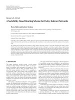
operate in their usual way. As shown in Figure 1,TQMuses
two modules, that is, “Flow State” and “QoS Manager”, to
accommodate the diverse characteristics of existing appli-
cations and their underlying transport protocols. When an
application is launched, some records are created in the
kernel space for system communication and maintenance
purposes. Without modifying either the kernel or the
application, the virtual flow state module in TQM collects
flow information from these records and presents this
information to the QoS Manager. The user can then interact
with the QoS Manager to specify directly those applications
which require enhanced QoS support. Subsequently, the QoS
Manager applies the flow information supplied by the flow
state module to transparently carry out EM operations on
behalf of the applications.
TQM achieves transparent QoS enhancement by means
of a packet redirection scheme. Specifically, the implementa-
tion of QoS-manager module is based on the functionality
of the IP firewall [17] as well as the divert socket [18]. IP
firewall filters packets traveling up or down the IP stack;
and it defines the target action on these filtered packets,
according to firewall rules. Instead of specifying typical target
actions such as ACCEPT or DENY, target DIVERT can
redirect filtered packets to a divert socket. Divert socket is
one element of general BSD socket and can be bound to
a specific port of the host for IP packet interception and
injection. Since the IP firewall is located at the bottom of
the IP stack, it redirects the IP flows which are specified
in divert messages received from the QoS manager to a
specific system port. The QoS-manager module employs the
divert socket to bind this specific port and then receives
the IP data packets from it. Using the same port, the EM-
Host
User space
Application
Socket API
QoS manager
EM
Data
flow
Divert
message
Flow state
Tr afficcontrol
Divert
socket
Out
In
Kernel space
Figure 1: Basic components and operations of TQM host. Note
that sender data flow is marked as “Out” (solid line) and receiver
data flow is marked as “In” (dotted line).
processed IP packets are then injected back into the general
network protocol stack and are subsequently processed using
regular system routines. Accordingly, the packet redirection
of TQM operates in a two-way manner. In the TQM sender,
the QoS Manager redirects data flows generated by the
applications and injects them into the protocol stack for
network transmission. Conversely, in the TQM receiver, the
QoS Manager redirects the data flows received from the
underlying network infrastructure and then injects them into
upper-layer applications.
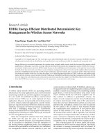
Figure 2 presents a detailed illustration of the major
components in the TQM QoS Manager. TQM provides a
transparent QoS enhancement capability through the use
of data planes and control planes. In the data plane, user-
specific flows are identified and the related flow informa-
tion is passed to the underlying EM. Executing the flow
information management function in the data plane involves
three separate components, namely the application filter,
the user interface, and the application list. Briefly, the
application filter collects the flow information relating to
launched applications from the flow state module, and users
monitor their applications on the application list through
the user interface. By accessing the user interface, a user can
view those flows which have been launched. Subsequently,
he or she can specify the particular flow (or flows) for
which enhanced QoS support is required. By querying the
application list, the application filter detects and discards
any flow information relating to applications which have not
been specified by a user.
Application list
Some applications, for example, DNS query, time services,
http services, and so forth, do not have strict QoS require-
ments. Therefore, TQM uses the application list to indicate
the multimedia applications for which the user specifies that
QoS enhancement support may be required. The user selects
4 EURASIP Journal on Advances in Signal Processing
Flow
information
Application
filter
Data plane
Control plane
User space
Kernel space
Flow state
Tr afficcontrol
QoS manager
User interface
1
EM
2
Divert
message
3
IP
packet
4
EM-processed
IP packet
Data flow
Application
list
vic
vls
···
Figure 2: TQM architecture.
these specific applications on the application list via the user
interface, and can arbitrarily add or delete selection records
on demand. By accessing this list, the application filter can
indicate to the flow state module the specific applications for
which it should collect flow information.
Application filter
Using the flow state module, the application filter retrieves
the flow information required to transparently start QoS
sessions on behalf of the applications. Generally, this infor-
mation is related to five tuples (i.e., the transport protocol,
the source IP address, the source port, the destination port,
and the destination address).When a user requests support
for a specific flow, this information is passed to the control
plane, which then establishes the QoS session.
In the control plane, the EMs set up QoS sessions on
behalf of the legacy applications. Importantly, the control
plane in the proposed TQM mechanism contains many
QoS EMs of different types. These EMs may be used
either separately or cooperatively in order to carry out
various functions. Consequently, TQM provides a flexible
and efficient mechanism for the QoS enhancement of diverse
applications. Based on the flow information received from
the data plane, the EM identifies the user-specified flow and
then intercepts the corresponding IP packets to carry out
the QoS enhancement process. The EM-processed packets
are then returned to the network protocol stack for further
processing. Note that IP flow packets may be added, deleted
or modified during QoS enhancement depending on the
particular EM type.
2.2. EM types
TQM comprises a collection of different EMs to support
video applications with diverse QoS requirements. Indi-
vidual EMs may function independently for a specific IP
flow or may cooperate with other EMs to improve the
overall QoS. The TQM architecture is sufficiently flexible to
support both the addition of new EMs and updates of the
algorithms upon which the EMs are based. According to the
general QoS solutions ranging from the underlying network
architectures to upper applications, there are three basic
examples of EM to support the QoS requirements of wireless
video transmissions, namely, packet mapping control, TCP-
friendly congestion control, and adaptive error control.
These three EMs are discussed briefly in the following
subsections.
2.2.1. Packet mapping control EM
In general, QoS architectures employ some form of traffic
category concept to support the implementation of scalable
and manageable wireless networks with service differentia-
tion capabilities. For example, the 3GPP working group has
defined four different QoS classes, that is, conversational,
streaming, interactive and background, based on a consider-
ation of the delay sensitivity of different applications. Mean-
while, the 802.11e standard prescribes eight different traffic
categories for wireless local area networks. Similarly, the
802.16 standard defines four different types of service flow
in wireless metropolitan area networks, namely, unsolicited
grant service, real-time polling service, nonreal-time polling
service, and best effort service.Through application-specific
QoS mapping mechanisms, data flows are assigned to the
appropriate traffic category and are then transmitted with
the corresponding priority. Furthermore, individual video
packets may also be categorized in accordance with their
loss and delay properties; and then assigned to different
prioritized transmission classes in order to optimize the
video quality under given rate or cost constraints.
To accommodate these various strategies, it is necessary
to provide differentiation both among multiple flows and
Chi-Huang Shih et al. 5
within single flow. The general differentiation parameters
include the IP source/destination address, the protocol, the
source/destination port number, and the type of service
(TOS) value. In the proposed TQM mechanism, the packet
mapping control EM maps the flows identified by the Flow
State module to user-specified traffic categories. Meanwhile,
differentiation within a single flow is achieved without
modifying the applications by transparently diverting the
IP packets to the packet mapping control EM. The packet
mapping control EM first identifies the packet using appro-
priate classification criteria (e.g., video frame/layer type) and
then maps the packet to the appropriate prioritized class. In
mapping the packet to the prioritized class, the EM either
directly forwards the identified packets to the underlying
network architecture or marks packets with the proper TOS
value according to the criteria specified by the underlying
architecture before packet forwarding.
2.2.2. TCP-friendly congestion control EM
Since the capacity of a wireless channel is scarce and time-
varying, bursty losses and excessive delays caused by network
congestion can significantly degrade the perceived video
quality. Accordingly, congestion control mechanisms aim
to minimize the impairment of the delivered video quality
caused by network congestion by reducing packet losses and
delays. Additionally, video streams must share the available
bandwidth equally with other TCP-based flows. Based
on the QoS requirements of multimedia transport, TCP-
friendly congestion control mechanisms smoothly adjust the
transmission rate and avoid increasing the latency by not
retransmitting lost packets. Two types of TCP-congestion
control mechanism are generally used for multimedia appli-
cations, namely sender-based rate adjustment and model-
based rate adjustment. The former mechanism is similar to
TCP in that it performs additive increase and multiplicative
decrease (AIMD) control at the sender end [19]. Conversely,
the latter scheme uses a throughput equation based on a
stochastic TCP model to adjust the transmission rate as a
function of the loss event rate and the round trip time (RTT)
[20, 21].
To transport video in a TCP-friendly manner, video
applications must match the output rate to the available
network bandwidth, as estimated by a TCP-friendly con-
gestion control protocol. One approach for achieving TCP-
friendly video transmission is for the video application
to use a rate control scheme to regulate the coded bit
stream under the constraint of certain given conditions
while simultaneously maximizing the user’s perception of
the media stream quality [22, 23]. However, this approach
generally requires modification of the original legacy applica-
tions. An alternative approach is to control the transmission
rate of the encoded video stream packets so as to obtain
atradeoff between the degree of TCP-friendliness and
the perceived media quality [24]. The TQM mechanism
proposed in this study constructs a TCP-friendly congestion
control protocol which operates totally transparently to
the legacy applications and supports these two approaches
to achieve the rate matching. In the first approach, the
video transcoding can be used to adapt the output video
stream to the available TFRC bandwidth [25]. The general
video transcoding parameters consist of frame size, frame
rate, and quantization value. In the second approach, the
TCP-friendly congestion control EM uses a simple packet
control mechanism to either discard packets according to
the priority classes they belong to or, if the output rate of
the video streams exceeds the TCP-friendly sending rate, to
postpone packet transmission until the next transmission
period.
2.2.3. Adaptive error control EM
Error-control schemes aim at coping with the wireless
error problems for high-bit-rate video transmissions over
error-prone wireless networks. Typical examples of error
control schemes presented in the literature include ARQ
and FEC. The objective of both schemes is to obtain a
higher data throughput by recovering corrupted packets.
However, the two schemes adopt different strategies to
achieve this objective. Specifically, ARQ retransmits lost
packets, whereas FEC deliberately generates redundant data
to enable the reconstruction of any video data which is lost
during transmission. Although it has been shown that ARQ
is more effective than FEC, its end-to-end retransmissions
may impede the timely presentation of video content.
Therefore, the FEC scheme is generally preferred for real-
time video applications. Since the loss condition changes
dynamically in wireless environments, and furthermore, the
self-induced congestion caused by the generation of excessive
redundant data has an adverse effect on the video quality,
it is desirable for FEC-control schemes to have the ability
to adapt dynamically to varying network conditions, that is,
to changes in the packet loss rate or the level of network
congestion. Therefore, the adaptive error control EM in the
proposed TQM mechanism installs the FEC encoder in the
data sender and the FEC decoder in the data receiver to
support the transparent FEC coding of video applications.
The current study focuses primarily on the integration
of these three EMs on the proposed TQM to carry out
the robust video transmission and the testing of an instant
frame-level FEC technique to adjust the number of redun-
dant packets according to the network conditions.
3. FEC-ON-TQM
3.1. Overall structure
The aim of FEC-on-TQM is to enhance the perceived
quality of the delivered video by transparently recovering
packet losses on behalf of legacy video applications with
no FEC capability. In this study, FEC-on-TQM integrates
three EMs mentioned in Section 2.2 to achieve a tradeoff
between robust video transmissions and efficient bandwidth
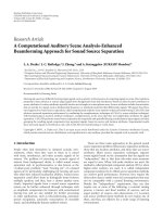
utilization. Figure 3 illustrates the end-to-end communi-
cation between two TQM hosts. In the video sender, the
packet mapping EM identifies the frame type of video
packets redirected by the QoS manager and forwards a
stream of video frames to the FEC EM. The FEC EM applies
6 EURASIP Journal on Advances in Signal Processing
TQM sender
Frames
FEC EM
Packet mapping EM
Congestion
control EM
Data
Transmission
channel
Feedback
TQM receiver
Frames
FEC EMLDA
Congestion
control EM
Figure 3: FEC-on-TQM transmission scheme.
forward error correction on each frame using the TCP-
friendly transmission rate passed on from the congestion
control EM, producing a data packet stream including
source video packets and redundant packets for network
transmission. In the video receiver, the FEC EM collects a
sequence of data packets belonging to the same frame and
performs a loss recovery operation if required, that is, if a
loss condition exists.
To improve the FEC efficiency, the QoS Manager in the
video sender requires knowledge of the current network
conditions such that the redundancy control function in
the FEC mechanism can be adapted accordingly. In FEC-
on-TQM, this is achieved by periodically sending feedback
packets from the QoS manager in the video receiver to
the QoS manager in the video sender. The feedback packet
is useful for the TQM sender in providing packet loss
rate and estimating the network round trip time. Since
TQM redirects the IP packets of specific applications, packet
loss information can be inspected by TQM. In addition
to monitoring the packet loss rate, the QoS manager in
the video receiver employs a loss differentiation algorithm
(LDA) to indicate the congestion signal by discriminating
congestion losses from wireless losses for all of the incoming
packets, that is, both the source packets and the redundant
packets. Two different types of LDA algorithm are commonly
employed in receivers nowadays, namely split-connection
LDA and end-to-end LDA. The former algorithms, for
example, agent-based LDA, differentiate losses using some
form of network assistance [26]. Conversely, end-to-end
LDA schemes employ a time-based approach and measure
queuing delays in an end-to-end manner. The measurement
metric used in end-to-end LDA algorithms may be either
the packet interarrival time [27] or the relative one-way trip
time (ROTT) [28]. Since split-connection LDA algorithms
generally require modification of the core network, the
current FEC-on-TQM implementation adopts an end-to-
end LDA scheme. If the LDA regards the loss as a congestion
loss, the congestion control EM includes it in the calculation
of TCP-friendly transmission rate. Note that in the current
deployment, the two end TQM hosts create a new connec-
tion to form a feedback channel to carry the packet loss
information computed in the receiver through the common
socket API. For RTP streams, these feedback messages could
be merged into RTCP packets to reduce the control packet
overhead [29].
3.2. FEC-on-TQM design
In this study, we use systematic Reed-Solomon erasure codes
RS (n, k) to protect video data from channel losses. The
RS encoder chooses k video data items as an FEC block
and generates (n-k) redundant data items for the block.
Every data item has its own sequence number used to
indicate the corresponding position within the block. With
this position information, the RS decoder can locate the
position of the lost items and then correct up to (n-k)lost
items. Furthermore, the FEC-on-TQM applies a packet-level
RS code as FEC since it enables full transparency at the
application layer and has a high efficiency over error-prone
wireless channels [30]. Packet-level FEC schemes group the
source data packets into blocks of a predetermined size k,
and then encode n
= k + h packets for network transmission,
where h
≥ 0 is the number of redundant packets. Provided
that k or more packets are successively received, the block can
be completely reconstructed. In FEC-on-TQM, one feedback
packet is sent from the video receiver to the video sender
for every FEC block. Note that packet-level FEC extends
the media stream simply by inserting redundant packets
into the stream. Therefore, the method requires only minor
modification to the source packets and supports a higher
degree of transparency.
Figure 4 illustrates the data format of RTP packets
through FEC-on-TQM. Other than the IP/UDP/RTP header,
FEC is applied only to the source data (i.e., the payload) of
the redirected IP packets. Following the FEC coding process,
redundant data is generated and grouped into redundant
packets in accordance with the header information on the
source packets. Furthermore, an additional FEC header
is added before the data portion to aid the decoding
process. The RTP structures of both the source packets and
the redundant packets are defined in accordance with the
recommendations of RFC 2733 (In RFC 2733, the length
of the RTP header is 12 bytes or more and the length of
the FEC header is 12 bytes. In the later IETF Internet draft,
the length of the FEC header is 10 bytes [31]) [32]. It is
noted that changing the size of the packets or modifying
the packet header requires a subsequent adjustment of the
length and checksum fields in the IP header for IP validation
purposes.Since the additional FEC header may cause the
packet length to exceed the path maximum transit unit
(MTU) size, the fragmentation may split a long packet into
Chi-Huang Shih et al. 7
IP
header
UDP
header
RTP
header
Source data
IP
header
UDP
header
RTP
header
FEC
header
Source data
(redundant data)
Figure 4: IP datagram format of RTP stream through FEC-on-
TQM.
two separate packets, resulting in a dependency between
the two packets. However, in the receiver end, one of these
packets may result in the corruption of the second packet,
and hence the efficiency of the FEC recovery process is
reduced. Based on the RTP header, FEC-on-TQM identifies
the video frame type that the redirected packets belong to
by extracting the payload type field and the video-specific
header attached to the RTP fixed header. In addition, the
timestamp field in the RTP header also helps the frame type
extraction since the RTP packets belonging to the same video
frame usually tagged with the similar timestamp value.
4. INSTANT FRAME-LEVEL FEC
This section develops the instant frame-level FEC technique
for real-time streaming video flows within TCP-friendly
constraints. To achieve a tradeoff between error correction
capacity and low-delay video transmission, the proposed
FEC technique determines the amount of FEC required by
every video frame in the presence of packet loss when video
frames are just dispatched by the streaming video application
or the video encoder. A detailed discussion of the proposed
instant frame-level FEC is presented in the paragraphs below.
4.1. TCP-friendly video flows with frame-level FEC
A TCP-friendly video flow needs to regulate its output rate
to match the TCP-friendly transmission rate. Based on a bit-
rate response function of Reno TCP [33], the TCP-friendly
bandwidth T (in bytes/s) is given by
T
=
S
r
2p/3+t
RTO
(3
3p/8)p(1 + 32p
2
)
,(1)
where S is the packet size in bytes, r is the round-trip time in
seconds, p is the current packet loss probability, and t
RTO
is
the TCP retransmit timeout value in seconds.
In MPEG video, the raw video data are encoded as
intracoded (I), predictive (P), and bidirectional (B) video
frames. An I frame is encoded without dependence on
any past frames. A P frame is encoded based on motion
differences from the previous I frame or P frame. B frames
are encoded based on the motion differences from the
immediate past and future I or P frames. Due to the coding
dependency, these three frame types (I, P, and B) have a
descending order of importance. After coding, the I, P, and
B frames are arranged in a periodic sequence which is called
group of picture (GOP). For instance, a typical GOP pattern
is IBBPBBPBBPBB and the GOP size is accordingly 12.
Each frame has to be converted into packets for network
transmission and the packet size should not be larger than
the path MTU along the traversing links from the sender to
the receiver. For a GOP of size L, the video sender transmits a
series of packet blocks at a frame rate R
f
frames per second:
k
1
, k
2
, , k
i
, , k
L
,(2)
where k
i
is the number of packets of ith video frame in the
GOP. The frame interval is 1/R
f
. Due to the different spatial
and temporal activities in the video encoding process, video
frames are of variable lengths. According to (1), the available
bandwidth allocated to the GOP is given by
T
GOP
= T ×
L
R
f
. (3)
In frame-level FEC, the systematic RS erasure code RS (n
i
, k
i
)
is applied as FEC to protect video frames. Given the target
loss probability P
target
, the estimated packet loss rate P and
fixed k
i
, the lower bound on n
i
can be computed using
P
target
=
n
i
j=n
i
−k
i
+1
n
i
j
p
j
(1 − p)
n
i
− j
. (4)
According to (4), the FEC encoder generates h
i
= n
i
− k
i
redundant packets for the ith video frame and the number of
packets transmitted to the network is n
i
. In the FEC decoder,
the ith video frame can be reconstructed when any k
i
or
more packets out of n
i
transport packets are successfully
received. In [34], the picture quality of MPEG-4 is showed
to be acceptable at a loss rate of 10
−5
and good at a loss rate
of 10
−6
. In this paper, the value of P
target
in (4) was set to 10
−6
to obtain high-visual-quality video experience.
Figure 5(a) illustrates the processing sequence of source
and redundant packets for the instant frame-level FEC. Fol-
lowing the frame i of k
i
source packets, the desired redundant
packets h
i
are generated and transmitted along with the
source packets to combat packet loss in the network. The
processing sequences of optimal frame-level FEC and GOP-
level FEC are showed in Figures 5(b) and 5(c),respectively.
Both techniques need to defer the FEC processing until an
entire GOP arrives. The difference between them is that the
optimal frame-level FEC adjusts the amount of FEC per
frame while the GOP-level FEC determines an appropriate
amount of FEC for a GOP.
For frame i, the video data bandwidth B
data
(i) and the
required FEC bandwidth B
req
(i) to achieve the target packet
loss probability can be easily computed as follows:
B
data
(i) = k
i
× S,(5)
B
req
(i) = n
i
× S. (6)
Therefore, the total bandwidth that the frame-level FEC can
allocate to the GOP must satisfy the following constraint:
L
i=1
B
req
(i) ≤ T
GOP
. (7)
8 EURASIP Journal on Advances in Signal Processing
IPBBP
k
1
h
1
k
2
h
2
k
3
h
3
k
4
h
4
k
5
h
5
···
B
k
L
h
L
Time
(a)
IPBBP
k
1
k
2
k
3
k
4
k
5
···
B
k
L
h
1
h
2
h
3
h
4
h
5
··· h
L
Time
(b)
IPBBP
k
1
k
2
k
3
k
4
k
5
···
B
k
L
h
GOP
Time
(c)
Figure 5: Sequence of source and FEC redundant packets: (a) instant frame-level FEC; (b) optimal frame-level FEC; (c) GOP-level FEC.
To cater for this rate constraint problem, the temporal scaling
approach can be used to adjust the amount of video data
while preserving the real-time requirement of streaming
video applications. In the temporal scaling approach, the
video frames with less importance level are discarded
before transmission to match the available TCP-friendly
transmission rate. For instance, the frame discarding order
canbeB,P,andIframe.
4.2. Classification of video frames
The GOP pattern in MPEG video is typically arranged as
follows:
IB
0,0
···B
0,N
BP
−1
P
1
···P
m
B
m,0
···B
m,N
BP
−1
P
m+1
···P
N
P
B
N
P
,0
···B
N
P
,N
BP
−1
,
(8)
where N
P
is the number of P frames in the GOP and N
BP
is the number of B frames in between an I and a P frame
or two P frames. Therefore, the number of B frames N
B
in the GOP is given by N
B
= (1 + N
P
) × N
BP
. Generally,
I frame is encoded with high-spatial quality in the GOP
and the subsequent P frames have a gradually degraded
spatial quality. Accordingly, the frame type and the frame
distance from the reference I frame are two basic criteria to
classify video frames in the GOP. Since losing I frame can
cause a significant impact on video quality for the entire
GOP, I frame has a highest priority. Due to the temporal
dependency, P frames which are closer to the reference I
frame has higher priority. As to B frames, which are not used
as references of other frames in the GOP, the temporal quality
degradation caused by continuous B-frame loss should be
considered in classifying video frames. According to the
distance of B frames from the reference I frame, B frames are
evenly chosen to form N
BP
frame groups of size N
P
as follows:
B
0,0
B
1,0
···B
N
P
,0
B
0,1
B
1,1
···B
N
P
,1
B
0,N
BP
−1
B
1,N
BP
−1
···B
N
P
,N
BP
−1
.
(9)
In each B-frame group, B frames which are closer to the
reference I frame have higher priority. Figure 6 shows the
I
P
1
P
2
··· P
N
P
B
0,0
B
1,0
··· B
N
P
,0
B
0,1
B
1,1
···
B
N
P
,1
···
B
0,N
BP
−1
B
1,N
BP
−1
···
B
N
P
,N
BP
−1
High priority
High priority
Figure 6: Video frame classification within a GOP.
classification of video frames in this study. Therefore, the
frame priority sequence in the GOP can be given by
IP
1
P
2
···P
N
P
B
0,0
B
1,0
···B
N
P
,0
B
0,1
···B
N
P
,1
···B
0,N
BP
−1
···B
N
P
,N
BP
−1
.
(10)
Based on this prioritized frame sequence, each frame in
the GOP pattern is associated with a priority distance from
the leading I frame. For instance, with the GOP pattern of
“IB
00
B
01
P
1
B
10
B
11
P
2
B
20
B
21
P
3
B
30
B
31
”, its corresponding pri-
ority sequence is “I
1
P
1
P
2
P
3
B
00
B
10
B
20
B
30
B
01
B
11
B
21
B
31
”and
thus the associated distance sequence of the GOP pattern can
berepresentedas“04815926103711”.
4.3. Adaptive frame rate allocation
The proposed FEC technique aims at minimizing the addi-
tional FEC processing delay while achieving the near-highest
video quality obtained by the optimal frame-level FEC
within TCP-friendly rate constraints. To achieve this goal,
the FEC performs an online rate allocation for video frames
and allows frame discarding to adjust the output data rate
without impairing the timing constraints of streaming video.
Upon receiving the frame i, the required bandwidth n
i
of the
frame is calculated using (4) to achieve the target packet loss
probability. Then, the FEC allocates the bandwidth of the
frame i, B
frame
(i), subject to the transmission rate budget and
the frame priorities. After the successful frame bandwidth
allocation, the frame i is delivered to the network with its
redundancy generated by the FEC.
Chi-Huang Shih et al. 9
Based on the video frame classification described in the
previous section, the bandwidth allocated to the video frame
should be adaptive to its priority distance from the reference
I frame. This adaptive frame rate allocation can be done
using a linear weighting factor related to the priority distance
of the video frame. Figure 7 illustrates the weighted rate
allocation of video frames. Denoting N as the maximum
priority distance in the GOP pattern and d
i
as the priority
distance between the frame i and the reference I frame, the
corresponding weight F
i
of the frame i is defined as follows:
F
i
=
N − d
i
N
. (11)
Using (11) and summing up the weights of all frames, the
allocation weight for the GOP can be obtained by
F
GOP
=
N
i=1
F
i
. (12)
Since I frame is the first encoded and delivered frame in
the GOP, the rate allocation starts by allocating enough FEC
bandwidth (n
1
× S), to I frame using (4). After I-frame
rate allocation, the available bandwidth for the subsequent
frames can be obtained:
T
avail
= T
GOP
− n
1
× S. (13)
Then, the weighted frame bandwidth of the frame i in the
GOP is calculated by
B
weight
(i) =
F
i
F
GOP
× T
avail
. (14)
Noted that the frame can be contiguously discarded when
the available TCP-friendly transmission rate is low or when
fast motion change occurs to induce larger frame size. For the
case of contiguous frame discarding, the available bandwidth
budget for the next frame accumulates as the number of
contiguous discarded frames increases. Let m be the number
of frames discarded contiguously before the frame i, and let
B
weight
(i, m) be the weighted frame bandwidth accumulated
from the frame (i-m) to the frame i,(14) can be modified as
follows:
B
weight
(i, m) =
i
j=i−m
F
j
F
GOP
× T
avail
. (15)
Furthermore, to better utilize the transmission rate budget,
the remaining frame bandwidth of the frame i, B
rem
(i), is
also added to the bandwidth budget of the frame (i +1).
Therefore, the available bandwidth for the frame i is given
by
B
avail
(i) = B
weight
(i, m)+B
rem
(i − 1). (16)
In allocating the frame bandwidth to video frames, we
employ the following set of strategies with respect to the type
of the frame i.
Nd
i
Distance
0
N
− d
i
N
1
We ig ht
F
d
i
Figure 7: Weighted rate allocation.
(i) For the B frame, if the available bandwidth B
avail
(i)
is less than the required bandwidth B
req
(i), the frame
is discarded and accordingly, its available bandwidth
will be added to the bandwidth budget of the next
frame.
(ii) For the P frame, if the available bandwidth B
avail
(i)is
less than the required bandwidth B
req
(i), the frame
will borrow from the remaining transmission rate
budget, T
rem
, until either the required bandwidth
is met or the transmission rate budget is exhausted
since the loss of one P frame can cause the severe
quality degradation of other P and B frames. The P
frame is discarded when the remaining transmission
rate budget is less than the amount of source data
B
data
(i).
(iii) For the I frame, the I frame is never discarded since
the loss of I frame causes the coding failure of an
entire GOP.
The adaptive frame rate allocation algorithm used in the
instant frame-level FEC is described in Algorithm 1.
5. PERFORMANCE RESULTS
5.1. Experimental setup
To evaluate the performance of the proposed FEC-on-TQM,
a prototype implementation of TQM was developed on the
FreeBSD and Linux platforms.As shown in Figure 8, the
experimental setup consisted of a video sender, a video
receiver and a network bridge, and these three hosts were
running on Linux-based x86 PCs. The network bridge
bridged packets between networks and produced packet
losses and transfer delay for a specified data flow. In the
video server, MPEG video sequences were transmitted to
the video receiver using the VideoLAN Server (VLS) [35].
FEC-on-TQM EMs were constructed in the video sender and
the video receiver, respectively, and an omniscient scheme
was built to provide an end-to-end LDA function [36].
The wireless network employed an 802.11b access point
10 EURASIP Journal on Advances in Signal Processing
i = 1; //begin calculation from the first frame in the video stream
While (not end of stream)
{
Calculate B
req
(i) using (4) and (6);
Switch (type of frame i)
{
Case “I”:
Calculate T
GOP
using (1) and (3);
T
rem
= T
GOP
; B
rem
(i) = m = 0;
B
frame
(i) = min{T
rem
, B
req
(i)};
Break;
Case “P”:
Calculate B
avail
(i) using (16);
If (T
rem
<B
data
(i)){
B
frame
(i) = 0; // Frame i is discarded
m
= m +1;
} Else {
B
frame
(i) = min{T
rem
, B
req
(i)};
m
= 0;
}
B
rem
(i) = B
rem
(i − 1) + B
avail
(i) − B
frame
(i);
Break;
Case “B”:
Calculate B
avail
(i) using (16);
If (B
req
(i) >B
avail
(i)){
B
frame
(i) = 0; // Frame i is discarded
m
= m +1;
} Else {
B
frame
(i) = B
req
(i)
m
= 0;
}
B
rem
(i) = B
rem
(i − 1) + B
avail
(i) − B
frame
(i);
Break;
}
If (B
frame
(i) >B
data
(i))
FEC is deployed for frame i, the FEC bandwidth allocated to frame i is B
frame
(i);
T
rem
= T
rem
− B
frame
(i);
i
= i +1;
}
Algorithm 1: Adaptive rate allocation algorithm.
Video
sender
Network
bridge
Hub
AP
Video
receiver
Bit errors
Packet losses, delay
Figure 8: Experimental setup.
(AP) operating in distributed coordination function (DCF)
mode to connect the video receiver. The video receiver was
arranged in clear line of sight (LoS) of the AP to ensure
the channel quality and generated packet losses caused by
wireless bit errors.
5.2. TQM overhead
As described in Section 2, TQM adopts a flow redirection
approach to support FEC functionality for legacy applica-
tions. In this approach, packets are copied from the kernel
space to the user space and are then sent back to the
kernel space following processing. Clearly, this processing
overhead introduces the additional delays at the sender
and the receiver end. In multimedia applications, delay is
a major factor influencing the perceived media quality. To
evaluate the overhead incurred by the TQM scheme, an
experiment was performed to determine the average delay
time incurred by the TQM flow redirection process for
packets of various sizes. In the experiment, the video sender
sent ICMP ping packets to the video receiver, and then
waited for the echo packets to be returned. Each echo packet
was redirected to the TQM module, processed, and then
injected to protocol stack for transmission. The RTT was
thenmeasuredatthevideosenderendinordertocalculate
the difference between the TQM-redirected RTT and the
non-TQM-redirected RTT. The corresponding results are
presented in Tab le 1 for ICMP packets of four different sizes.
It can be seen that the difference between the directed and
nondirected RTTs increases with an increasing packet size.
Chi-Huang Shih et al. 11
However, the difference between the two times is very small.
For a 1024-byte ICMP packet, which is around the typical
packet size in most video applications, the RTT increases by
only 0.276% when the flow is redirected to TQM. In other
words, compared to the total transmission and processing
delays incurred along the path between the sender and the
receiver, the TQM overhead is relatively minor.
A second experiment was then performed to investigate
whether the additional delays caused by TQM and FEC-on-
TQM would accumulate to such an extent that they affected
the overall playout time of video applications. For FEC-
on-TQM, the frame type extraction time, the FEC encod-
ing/decoding time, and the redirection delay are considered
to measure the cumulative delay. Using the same setup as
that shown in Figure 8, long-lived video sequences were sent
from the video sender to the video receiver. The number of
FEC redundant packets was set to a static value of 1 for each
video frame. Since FEC decoding is not triggered in the TQM
receiver under loss-free conditions, an assumption was made
that one transported packet per FEC block was lost during
transmission. The total playout time was estimated at the
receiver and was then compared with the playout time with
no flow redirection or cumulative delays. Ta bl e 2 presents
the results obtained for eight different video sequences. It
is observed that the TQM redirection delay does not exceed
90 milliseconds for any of the sequences. Furthermore, for
the case of FEC-on-TQM, it can be seen that the FEC
coding operations result in an additional cumulative delay
of approximately 3-4 milliseconds. In practice, however, this
additional delay can be easily absorbed by the application
bufferandwillhavenoeffect on the user’s perception of the
delivered video quality. In the current experimental setup,
both the video sender and the video receiver are fitted
with Pentium-4 1.8 G processors and 256 MB of memory.
The experimental results suggest that this configuration is
sufficient to support the proposed TQM.
5.3. The FEC-on-TQM performance
To facilitate a controlled environment for performance
measurement purpose, the video application at the sender
is replaced by an emulator that feeds the frame of stored
MPEG-4 video clips at the real-time frame rate to the video
receiver. The rest of experimental set-up keeps unchanged.
The video sequence “Foreman” of CIF format is used in
this experiment. The videoclip is transmitted at a frame rate
25 frames per second and the GOP size is 9. In general,
video frames are segmented into packets for transmission.
Therefore, the application-level quality depends not only
on the successful recovery of lost packets, but also on
the dependency relations and delay constraint between
the individual video frames. A frame is considered to be
decodable at the video receiver when at least a fixed portion
DT (decodable threshold) of the data in each frame is
received in time and all of the frames it depends on are also
decodable. In the experiment, the stream is transmitted in
packets of 1Kbytes and the value of DT issetto1forall
video frames to observe error performance by dismissing
the effect of error resilience features of video transport. The
1-P
bg
1-P
gb
P
bg
P
gb
Loss rate = 0
Good
state
Bad
state
Loss rate = 1
Figure 9: Gilbert model.
video receiver processes the packet arrival in accordance
with the hard real-time constraint model presented in [10].
Also, we implement three FEC schemes including the instant
frame-level FEC, the optimal frame-level FEC and the GOP-
level FEC scheme on FEC-on-TQM. For all three schemes,
TCP-friendly transmission rate is calculated for every GOP.
As in [20], t
RTO
is typically set to four times of the round
trip time r. In order to match the TCP-friendly sending
rate with real-time constraints, both the optimal frame-level
scheme and the GOP-level scheme employ the temporal
scaling technique to discard frames based on the video frame
priority described in Section 4.2.
In this evaluation, either congestion loss or wireless loss
causes the end-to-end packet loss. A Gilbert model or a two-
state Markov model is used to generate burst loss patterns
over the transmission channel (Figure 9). The two states of
the model are Good-state and Bad-state. In the network
bridge, we employ a packet-level Gilbert model to drop
packets with the parameters of average packet loss rate (P
B
)
andaverageburstpacketlosslength(L
B
). In Good-state, a
packet is dropped with the probability of 0, while in Bad-
state, a packet is dropped with the probability of 1. The
transition probabilities of P
gb
and P
bg
can be derived by the
values of P
B
and L
B
as follows:
P
bg
=
1
L
B
, P
gb
= P
bg
×
P
B
1 − P
B
. (17)
In the video receiver, on the other hand, a bit-level Gilbert
model is used to model packet loss due to bit errors in the
wireless channel. This bit-level model is described by an
average bit error rate (P
b
) and an average burst bit error
length (L
b
). A packet of size τ in bits is dropped when at
least one bit within τ bits is lost. Ta bl e 3 presents the system
parameter settings for the network.
To verify the performance of FEC schemes designed for
delay-sensitive video service, we compare the end-to-end
frame delay among three FEC schemes built on TQM in
different network conditions. The end-to-end frame delay
is defined as the time difference between the frame release
time in the video sender application and the arrival time of
the similar frame in the video receiver application. When
the frames are discarded by FEC schemes or are lost during
transmission, they are excluded from the calculation of end-
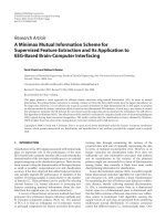
to-end delay. Figure 10 shows the end-to-end frame delay
analysis of three FEC schemes with P
B
= 0.01 and P
b
= 10
−6
.
It is noted that the instant frame-level scheme performs
the FEC encoding process on a frame-by-frame basis, while
both the optimal frame-level and the GOP-level scheme
12 EURASIP Journal on Advances in Signal Processing
Table 1: Flow redirection overhead.
ICMP packet
size (bytes)
Non-TQM-
redirected RTT
(ms)
TQM-redirected
RTT (ms)
RTT difference
RTT difference/
non-TQM-redirected
RTT
56 0.975 0.981 0.006 0.615%
512 2.579 2.587 0.008 0.310%
1024 4.344 4.356 0.012 0.276%
2048 6.849 6.864 0.015 0.219%
Table 2: Cumulative delay of FEC-on-TQM scheme.
Video sequence Total length Redirection delay (ms) Redirection + FEC coding delay (ms)
Cars 56 min 86.39 89.68
X-Men 55 min, 25 s 89.25 92.16
Mission impossible 63 min, 6 s 85.55 88.85
Brokeback mountain 65 min, 39 s 83.66 86.63
Final destination 45 min, 50 s 88.21 91.85
The Da Vinci code 76 min, 46 s 85.36 88.06
Monster house 45 min, 6 s 87.85 90.98
World Trade Center 53 min, 14 s 86.68 90.16
Table 3: Network settings.
Parameters Scenario 1 Scenario 2
Delay 12.5 ms 12.5 ms
P
B
0.01 0.01, 0.02, ,0.1
L
B
33
P
b
10
−6
,10
−5
, ,10
−1
10
−3
L
b
80 80
defers the encoding process until all video frames within
the GOP are received. From Figure 10, we can observe that:
(1) the instant frame-level scheme has much smaller end-
to-end frame delay than other two schemes and the delay
values are below 40 milliseconds (i.e., frame interval); (2)
for the optimal frame-level or the GOP-level scheme, the
GOP buffering results in a sawtooth delay curve and peaks
in the curve are correlated with the periodic insertion of I
frames; and (3) the end-to-end frame delays of the GOP-level
scheme are slightly smaller than that of the optimal frame-
level scheme, since the GOP-level scheme performs the FEC
encoding on a GOP and this requires less redundancies for
network transmission to protect the entire GOP against the
fixed network packet loss.
In the first experimental scenario, the bit error rate is
varied from 10
−6
to 10
−1
as the packet loss rate is fixed
to 0.01. Figures 11 and 12 show the average end-to-end
frame delay and the average PSNR, respectively. It is noted
that for the bit error rate
= 10
−1
, all packets are lost and
none of video frames is available to measure the end-to-end
frame delay. From Figures 11 and 12, it can be seen that
for the instant frame-level scheme: (1) the average end-to-
end frame delay is below 40 milliseconds as the bit error
rate varies, and (2) the average PSNR curve is close to that
of the optimal frame-level scheme and the largest PSNR
1009080706050403020100
Frame number
Instant frame-level FEC
Optimal frame-level FEC
GOP-level FEC
0
80
160
240
320
400
480
560
End-to-end frame delay (ms)
Figure 10: End-to-end timing between frames 1–100 with param-
eters P
B
= 0.01, P
b
= 10
−6
.
difference of 0.52 dB occurs as the bit error rate is 10
−2
.We
also observe that compared to the GOP-level scheme, the
optimal frame-level scheme has lower average PSNR value
with the larger end-to-end frame delay. Figures 13 and 14
show the performance results for another scenario. As the
packet loss rate is increased, the TCP-friendly sending rate
decreases accordingly. Besides the similar observations as in
the first scenario, the difference in the average PSNR value
between the instant frame-level scheme and the optimal
frame-level scheme is ranged from 0.01 dB to 0.71 dB. In
Figure 13, the delay gap between the optimal frame-level
scheme and the GOP-level scheme becomes large as the
packet loss rate exceeds 0.01. This is because that the amount
of discarded frames increases in the optimal frame-level
scheme to match the low TCP-friendly sending rate and
the frames with high priority, such as I frames, usually
Chi-Huang Shih et al. 13
10
−2
10
−3
10
−4
10
−5
10
−6
Bit error rate
Instant frame-level FEC
Optimal frame-level FEC
GOP-level FEC
0
40
80
120
160
200
240
280
320
360
400
440
480
Average end-to-end frame delay (ms)
Figure 11: Comparison of end-to-end frame delays with varied bit
error rate.
10
−1
10
−2
10
−3
10
−4
10
−5
10
−6
Bit error rate
Instant frame FEC
Optimal frame FEC
GOP FEC
0
4
8
12
16
20
24
28
32
36
Average PSNR (dB)
Figure 12: PSNR comparison with varied bit error rate.
gains transmission opportunities to cause a large end-to-
end frame delay. To conclude, the experimental results show
that the instant frame-level scheme better preserves the
timing aspects of real-time streaming video while achieving
the near-highest video quality that the optimal frame-level
scheme can obtain within the TCP-friendly rate constraints.
Therefore, the proposed scheme transparently supports the
robust video transmission on behalf of video applications
and is suitable for the provision of high quality real-time
video streaming with low delay.
6. CONCLUSIONS
This paper has developed a transparent QoS mechanism
designated as TQM to transparently establish QoS sessions
on behalf of multimedia applications over the wireless
0.10.090.080.070.060.050.040.030.020.01
Packet loss rate
Instant frame-level FEC
Optimal frame-level FEC
GOP-level FEC
0
40
80
120
160
200
240
280
320
360
400
440
480
520
Average end-to-end frame delay (ms)
Figure 13: Comparison of end-to-end frame delays with varied
packet loss rate.
0.10.090.080.070.060.050.040.030.020.01
Packet loss rate
Instant frame-level FEC
Optimal frame-level FEC
GOP-level FEC
16
18
20
22
24
26
28
30
32
34
Average PSNR (dB)
Figure 14: PSNR comparison with varied packet loss rate.
Internet. With no modification required to the existing
legacy applications, TQM uses an efficient packet redirection
scheme to divert user-specified flows for QoS enhance-
ment processing and provides a suitable platform for the
implementation of different QoS EMs. In TQM, EMs may
function either independently or with other EMs to improve
the overall QoS enhancement. As a first step, this study
has discussed the implementation involved in integrating
available EMs to support the transparent loss recovery based
on FEC. The FEC-on-TQM module uses an instant frame-
level FEC technique to achieve the near-highest video quality
that the optimal frame-level scheme can obtain within the
TCP-friendly rate constraints for real-time streaming video
applications. The experimental results have shown that: (1)
the overheads incurred by the proposed TQM scheme are
minor compared to the total transmission and processing
14 EURASIP Journal on Advances in Signal Processing
delays incurred along the path between the sender and the
receiver, and (2) FEC-on-TQM successfully integrates several
EMs to carry out the proposed instant frame-level FEC
technique, resulting in a low-delay, good-visual-quality video
experience. Future studies include the testing of network-
adaptive video applications, such as Helix video server,
on FEC-on-TQM, and the integration of EMs to further
improve the overall QoS of diverse multimedia applications
over the wireless Internet.
REFERENCES
[1] J. Wroclawski, The use of RSVP with IETF Integrated Services,
RFC 2210, September 1997.
[2] S. Black, D. Black, M. Carlson, E. Davies, Z. Wang, and W.
Weiss, “An architecture for differentiated services,” RFC 2475,
December 1998.
[3] Q. Zhang, W. Zhu, and Y Q. Zhang, “End-to-end QoS for
video delivery over wireless Internet,” Proceedings of the IEEE,
vol. 93, no. 1, pp. 123–133, 2005.
[4] Quality of service (QoS) concept and architecture, 3GPP TS
23.107, September 2003.
[5] IEEE Standard, “Local and metropolitan area networks—
specific requirements part 11: wireless LAN medium access
control (MAC) and physical layer (PHY) specifications
amendment 8: medium access control (MAC) quality of
Service enhancements,” pp.1–189, 2005.
[6] IEEE Standard, “802.16-2004 part 16: air interface for fixed
broadband wireless access systems,” October 2004.
[7] K. Nahrstedt, D. Xu, D. Wichadakul, and B. Li, “QoS-aware
middleware for ubiquitous and heterogeneous environments,”
IEEE Communications Magazine, vol. 39, no. 11, pp. 140–148,
2001.
[8] Y B. Miao, W S. Hwang, and C K. Shieh, “A transparent
deployment method of RSVP-aware applications on UNIX,”
Computer Networks, vol. 40, no. 1, pp. 45–56, 2002.
[9] L. Munoz, M. Garcia, J. Choque, R. Aguero, and P. Mahonen,
“Optimizing Internet flows over IEEE 802.11b wireless local
area networks: a performance-enhancing proxy based on
forward error correction,” IEEE Communications Magazine,
vol. 39, no. 12, pp. 60–67, 2001.
[10] K. Park and W. Wang, “QoS-sensitive transport of real-time
MPEG video using adaptive redundancy control,” Computer
Communications, vol. 24, no. 1, pp. 78–92, 2001.
[11] O. Ait-Hellal, E. Altman, A. Jean-Marie, and I. A. Kurkova,
“On loss probabilities in presence of redundant packets and
several trafficsources,”Performance Evaluation, vol. 36-37, pp.
485–518, 1999.
[12] K. Park and W. Willinger, Self-Similar Network Trafficand
Performance Evaluation, Wiley-Interscience, New York, NY,
USA, 2000.
[13] S. Floyd and K. Fall, “Promoting the use of end-to-end
congestion control in the Internet,” IEEE/ACM Transactions on
Networking, vol. 7, no. 4, pp. 458–472, 1999.
[14] H. Wu, M. Claypool, and R. Kinicki, “Adjusting forward error
correction with temporal scaling for TCP-friendly streaming
MPEG,” ACM Transactions on Multimedia Computing, Com-
munications, and Applications, vol. 1, no. 4, pp. 315–337, 2005.
[15] Y. Yuan, B. F. Cockburn, T. Sikora, and M. Mandal, “Efficient
allocation of packet-level forward error correction in video
streaming over the Internet,” Journal of Electronic Imaging,
vol. 16, no. 2, Article ID 023012, 12 pages, 2007.
[16] M. Baldi and Y. Ofek, “End-to-end delay analysis of videocon-
ferencing over packet-switched networks,” IEEE/ACM Trans-
actions on Networking, vol. 8, no. 4, pp. 479–492, 2000.
[17] Linux IP firewall HOWTO,, /LDP/
HOWTO/Firewall-HOWTO.html.
[18] Divert sockets, Sockets-min-
i-HOWTO.html#toc6.
[19] R. Rejaie, M. Handley, and D. Estrin, “Quality adaptation for
congestion controlled video playback over the Internet,” ACM
SIGCOMM Computer Communication Review, vol. 29, no. 4,
pp. 189–200, 1999.
[20]S.Floyd,M.Handley,J.Padhye,andJ.Widmer,“Equation-
based congestion control for unicast applications,” in Pro-
ceedings of the ACM Annual Conference of the Special Interest
Group on Data Communication (SIGCOMM ’00), pp. 43–56,
Stockholm, Sweden, August-September 2000.
[21] M. Handley, S. Floyd, J. Pahdye, and J. Widmer, “TCP friendly
rate control (TFRC): protocol specification,” RFC3448, Jan-
uary 2003.
[22] D. Wu, Y. T. Hou, W. Zhu, et al., “On end-to-end architecture
for transporting MPEG-4 video over the Internet,” IEEE
Transactions on Circuits and Systems for Video Technology,
vol. 10, no. 6, pp. 923–941, 2000.
[23] Q. Zhang, W. Zhu, and Y Q. Zhang, “Resource allocation for
multimedia streaming over the Internet,” IEEE Transactions on
Multimedia, vol. 3, no. 3, pp. 339–355, 2001.
[24] Z. Wang, S. Banerjee, and S. Jamin, “Media-friendliness of a
slowly-responsive congestion control protocol,” in Proceedings
of the 14th International Workshop on Network and Operating
System Support for Digital Audio and Video (NOSSDAV ’04),
pp. 82–87, Cork, Ireland, June 2004.
[25] V. Samata, R. Olivera, A. Dixit, P. Aghera, P. Zerfos, and S. Lu,
“Impact of video transcoding parameters on dynamic video
transcoding,” in Proceedings of the 1st International Conference
on Communication System Software and Middleware (COM-
SWARE ’06), New Delhi, India, January 2006.
[26] V. Arya and T. Turletti, “Accurate and explicit differentiation
of wireless and congestion losses,” in Proceedings of the 23rd
International Conference on Distributed Computing Systems
(ICDCS ’03), Providence, RI, USA, May 2003.
[27] S. Biaz and N. Vaidya, “Discriminating congestion losses from
wireless losses using inter-arrival times at the receiver,” in
Proceedings of the IEEE Symposium on Application-Specific
Systems and Software Engineer (ASSET ’99), pp. 10–17,
Richardson, Tex, USA, March 1999.
[28] Y. Tobe, Y. Tamura, A. Molano, S. Ghosh, and H. Tokuda,
“Achieving moderate fairness for UDP flows by path-status
classification,” in Proceeding of the 25th Annual IEEE Con-
ference on Local Computer Networks (LCN ’00), pp. 252–261,
Tampa, Fla, USA, November 2000.
[29] H. Schulzrinne, S. Casner, R. Frederick, and V. Jacobson,
“RTP: a transport protocol for real-time applications,” RFC
3550, July 2003.
[30] F. Borgonovo and A. Capone, “Efficiency of error-control
schemes for real-time wireless applications on the Gilbert
channel,” IEEE Transactions on Vehicular Technology, vol. 54,
no. 1, pp. 246–258, 2005.
[31] A. Li, “RTP payload format for generic forward error cor-
rection,” Internet Draft draft-ietf-avt-ulp-18, IETF, work in
progress, June 2006.
[32] J. Rosenberg and H. Schulzrinne, “An RTP payload format for
generic forward error correction,” RFC 2733, December 1999.
Chi-Huang Shih et al. 15
[33] J. Padhye, V. Firoiu, D. F. Towsley, and J. F. Kurose, “Modeling
TCP reno performance: a simple model and its empirical
validation,” IEEE/ACM Transactions on Networking, vol. 8,
no. 2, pp. 133–145, 2000.
[34] S. Gringeri, R. Egorov, K. Shuaib, A. Lewis, and B. Basch,
“Robust compression and transmission of MPEG-4 video,”
in Proceedings of the 7th ACM International Conference on
Multimedia (MULTIMEDIA ’99), pp. 113–120, Orlando, Fla,
USA, October 1999.
[35] The VideoLAN server, />.html.
[36] S. Cen, P. C. Cosman, and G. M. Voelker, “End-to-end
differentiation of congestion and wireless losses,” IEEE/ACM
Transactions on Networking, vol. 11, no. 5, pp. 703–717, 2003.