Báo cáo hóa học: " Review Article An Overview on Wavelets in Source Coding, Communications, and Networks" doc
Bạn đang xem bản rút gọn của tài liệu. Xem và tải ngay bản đầy đủ của tài liệu tại đây (1.4 MB, 27 trang )
Hindawi Publishing Corporation
EURASIP Journal on Image and Video Processing
Volume 2007, Article ID 60539, 27 pages
doi:10.1155/2007/60539
Review Article
An Overview on Wavelets in Source Coding,
Communications, and Networks
James E. Fowler
1
and B
´
eatrice Pesquet-Popescu
2
1
Department of Electrical & Computer Engineering, GeoResources Institute, Mississippi State University, P.O. Box 9627,
Mississippi State, MS 39762, USA
2
D
´
epartement Traitement du Signal et des Images,
´
Ecole Nationale Sup
´
erieure des T
´
el
´
ecommunications, 46 rue Barrault,
75634 Paris, France
Received 7 January 2007; Accepted 11 April 2007
Recommended by Jean-Luc Dugelay
The use of wavelets in the broad areas of source coding, communications, and networks is sur veyed. Specifically, the impact of
wavelets and wavelet theory in image coding, video coding, image interpolation, image-adaptive lifting transforms, multiple-
description coding, and joint source-channel coding is overviewed. Recent contributions in these areas arising in subsequent
papers of the present special issue are described.
Copyright © 2007 J. E. Fowler and B. Pesquet-Popescu. This is an open access article distributed under the Creative Commons
Attribution License, which permits unrestricted use, distribution, and reproduction in any medium, provided the original work is
properly cited.
1. INTRODUCTION
Wavelet transforms are arguably the most powerful, and
most widely-used, tool to arise in the field of signal pro-
cessing in the last several decades. Their inherent capac-
ity for multiresolution representation akin to the operation
of the human visual system motivated a quick adoption
and widespread use of wavelets in image-processing applica-
tions. Indeed, wavelet-based algorithms have dominated im-
age compression for over a decade, and wavelet-based source
coding is now emerging in other domains. For example, re-
cent wavelet-based video coders exploit wavelet-based tem-
poral filtering in conjunction with motion compensation to
yield effective video compression with full temporal, spatial,
and fidelity scalability. Additionally, wavelets are increasingly
used in the source coding of remote-sensing, satellite, and
other geospatial imagery. Fur thermore, wavelets are start-
ing to be deployed beyond the source-coding realm w ith
increased interest in robust communication of images and
video over both wired and wireless networks. In particu-
lar, wavelets have been recently proposed for joint source-
channel coding and multiple-description coding. This spe-
cial issue collects a number of papers that explore these
and other latest advances in the theory and application of
wavelets.
Here, in this introductory paper to the special issue, we
provide a general overview of the application of wavelets and
wavelet theory to the signal representation, source coding,
communication, and network transmission of images and
video. The main body of this paper is partitioned into two
major parts: we first cover wavelets in signal representation
and source coding, and then explore wavelets in communi-
cations and networking. Specifically, in Section 2,wefocus
on wavelets in image coding, video coding, and image inter-
polation, as well as image-adaptive lifting transforms. Then,
in Section 3, we explore the use of wavelets in multiple-
description coding and joint source-channel coding as em-
ployed in communication and networking applications. Fi-
nally, we make some concluding remarks in Section 4.Brief
overviews of the papers in the special issue are presented
at the end of relevant sections throughout this introductory
paper—these overviews are demarked by boldfaced headings
to facilitate their location.
2. WAVELETS IN SIGNAL REPRESENTATION
AND SOURCE CODING
In the most elemental s ense, wavelets provide an expansion
set (usually a basis) that decomposes an image simultane-
ously in terms of frequency and space. Thus, signal represen-
tation—the representation of a signal using an expansion set
and corresponding expansion coefficients—can perhaps be
considered the most fundamental task to which wavelets are
2 EURASIP Journal on Image and Video Processing
applied. Combining such a signal representation with quan-
tization and some form of bitstream generation yields im-
age/video compression schemes; such source coding consti-
tutes perhaps the most widespread practical application of
wavelets. In this section, we overview the role of wavelets
in current applications of both signal representation and
source coding. First, we focus on source coding by examin-
ing the use of wavelets in image and video coders in Sections
2.1 and 2.2,respectively.InSection 2.3, we discuss image-
adaptive wavelet transforms that have been proposed to im-
prove signal-representation capabilities by adapting to local
image features. Finally, in Section 2.4, we explore wavelet-
based signal representations for the interpolation (magnifi-
cation) of image data.
2.1. Image coding
Over the last decade, wavelets have established a dominant
presence in the task of 2D image compression, and they are
increasingly being considered for the compression of 3D im-
agery as well. Wavelets are attr active in the image-coding
problem due to a tradition of excellent rate-distortion per-
formance coupled with an inherent capacity for progressive
transmission wherein successive reconstructions of the image
are possible as more and more of the compressed bitstream
is received and decoded. Below, we overview several salient
concepts in the field of image coding, including multidi-
mensional wavelet transforms, coding procedures applied to
such transforms, as well as coding methodology for general
imagery of shape other than traditional rectangular scenes
(i.e., shape-adaptive coding). The reader is referred elsewhere
for more comprehensive and in-depth surveys of 2D image
coding (e.g., [1]), 3D image coding (e.g ., [2]), and shape-
adaptive coding (e.g., [3]).
2.1.1. Multidimensional wavelet transforms
A single stage of a 1D discrete wavelet transform (DWT) de-
composes a 1D signal into a lowpass signal and a highpass
signal. Multidimensional wavelet decompositions are typi-
cally constructed by such 1D wavelet decompositions applied
independently along each dimension of the image dataset,
producing a number of subbands. The decomposition proce-
dure can be repeated recursively on one or more of the sub-
bands to yield multiple levels of decomposition of lower and
lower resolution.
The most commonly used multidimensional DWT struc-
ture consists of a recursive decomposition of the lowest-
resolution subband. This dyadic decomposition structure is
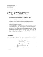
illustrated for a 2D image in Figure 1(a). In a 2D dyadic
DWT, the original image is decomposed into four subbands
each being one fourth the size of the original image, and
the lowest-resolution subband (the baseband)isrecursively
decomposed. The dyadic transform structure is trivially ex-
tended to 3D imagery as illustrated in Figure 1(b)—a single
stage of 3D decomposition yields 8 subbands with the base-
band recursively decomposed for a 3D dyadic transform.
Alternative transform structures arise when subbands
other than, or in addition to, the baseband are subjected
to further decomposition. Generally referred to as wavelet-
packet transforms, these decomposition structures can be
fixed (like the dyadic structure), or be optimally adapted
for each image coded (i.e., a so-called best-basis transform
structure [4]). Packet transforms offer the potential to better
match the spatial or spatiotemporal characteristics of certain
imagery and can thereby at times yield greater coding effi-
ciency. Although not widely used for 2D image coding,
1
fixed
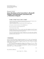
packet transforms, such as those illustr ated in Figure 2,have
been extensively deployed in 3D image coders and often yield
coding efficiency substantially superior to that of the dyadic
transform of Figure 1(b). In particular, the packet structure
of Figure 2(a) has been shown to be near optimal in certain
applications, producing coding performance nearly identical
to the optimal packet decomposition structure chosen in a
rate-distortion best-basis sense [6, 7].
Although there are many possible wavelet-transform fil-
ters, image-coding applications almost exclusively rely on the
ubiquitous biorthogonal 9/7 transform of [14] or the simpler
biorthogonal 5/3 transform of [15]. Biorthogonality facili-
tates symmetric extension at image boundar ies and permits
linear-phase FIR filters. Furthermore, experience has shown
that the biorthogonal 9/7 offers generally good coding per-
formance [16], while the biorthogonal 5/3 is attractive for
reducing computational complexity or for implementation
of reversible, integer-to-integer transformation [17, 18]. In
fact, the biorthogonal 9/7 and an integer-valued biorthogo-
nal 5/3 are the only transforms permitted by Part 1 of the
JPEG2000 standard [13], although coding extensions of Part
2[19] of the standard permit a greater variety of trans-
forms.
2.1.2. Coding procedures
Many wavelet-based coders for 2D and 3D images are based
on the following observations which tend to hold true for
dyadic decompositions of many classes of imagery: (1) since
most images are lowpass in nature, most signal energy is
compacted into the lower-resolution subbands; (2) most co-
efficients are zero for high-resolution subbands; (3) small- or
zero-valued coefficients (i.e., insignificant coefficients)tendto
be clustered together within a given subband; and (4) clusters
of insignificant coefficients in a subband tend to be located in
the same relative position as similar clusters in the subband
of the same orientation at the next higher-resolution level.
Wavelet-based image coders typically implement the fol-
lowing coding procedure. DWT coefficients are represented
in sign-magnitude form with the sign s and magnitudes
coded separately. Coefficient magnitudes are successively ap-
proximated via bitplane coding wherein the most signifi-
cant bit of all coefficient magnitudes is coded, fol l owed
by the next-most significant bit, and so forth. In practice,
1
The WSQ fingerprint coding standard [5] is one example of a fixed packet
transform in 2D.
J. E. Fowler and B. Pesquet-Popescu 3
B
3
V
3
H
3
D
3
V
2
H
2
D
2
V
1
H
1
D
1
(a) (b)
Figure 1: Dyadic DWT with three levels of decomposition. (a) 2D; (b) 3D.
(a) (b)
Figure 2: Examples of 3D wavelet-packet DWTs with three levels of decomposition. (a) 2D dyadic plus independent 1D dyadic; (b) three
independent 1D dyadic transforms.
such bitplane coding is usually implemented by perform-
ing two coding passes through the set of coefficients for
each bitplane—a significance pass and a refinement pass.In
essence, the significance pass describes the first bitplane
holding a nonzero bit for all the coefficients in the DWT
while the refinement pass produces a successive approxima-
tion of each coefficient after its most significant nonzero bit
is coded. The significance pass works by successively coding
a map—the significance map—of coefficients which are in-
significant relative to a threshold; the primary difference be-
tween wavelet-based coders lies in how this significance-map
coding is performed. Table 1 presents an overview of promi-
nent significance-map coding strategies which we discuss in
detail below.
Zerotrees are one of the most widely used techniques for
coding significance maps in wavelet-based coders. Zerotrees
capitalize on the fact that, in dyadic transforms, insignifi-
cant coefficients tend to cluster together within a subband,
and clusters of insignificant coefficients tend to be located in
the same location within subbands of different resolutions.
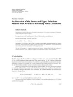
As illustrated in Figure 3(a), “parent” coefficients in a sub-
band can be related to “children” coefficients in the same rel-
ative location in a subband at the next higher resolution. A
zerotr ee is formed when a coefficient and all of its descen-
dants a re insignificant with respect to the current thresh-
old. The embedded zerotree wavelet (EZW) algorithm [8]
was the first image coder to make use of zerotrees. Later,
the set partitioning in hierarchical trees (SPIHT) algorithm
[9] improved upon the zerotree concept by adding a num-
ber of s orted lists that contain sets of coefficients (i.e., ze-
rotrees) and individual coefficients. Both EZW and SPIHT
were originally developed for 2D images. EZW has been ex-
tended to 3D in [20, 21]; SPIHT has been extended to 3D
in [22–27]. Whereas extending the 2D zerotree structure to
a 3D dyadic transform is simple, fitting zerotrees to the 3D
packet transforms of Figure 2 is less straightforward. The
4 EURASIP Journal on Image and Video Processing
Table 1: Strategies for sig nificance-map coding in wavelet-based still image coders.
Strategy Prominent examples Methodology Notes
Zerotrees
EZW [8], SPIHT [9]
Cross-scale trees of coefficients
plus arithmetic coding
Widely used
Set partitioning
SPECK [10, 11], BISK [12]
Set splitting into subsets plus
arithmetic coding
No cross-subband processing
Conditional coding
JPEG2000 [13]
Multicontext arithmetic coding of
small blocks; arithmetic coding;
optimal block truncation
Superior rate-distortion performance;
cross-subband processing confined to
block-truncation process
(a) (b)
Figure 3: Zerotrees in (a) the 2D dyadic transform of Figure 1(a),(b)the3DpackettransformofFigure 2(a).
asymmetric zerotree structure originating in [25] and illus-
trated in Figure 3(b) typically provides the best performance
for the packet transform of Figure 2(a).
Despite the prominence of zerotree-based algorithms, re-
cent work [28] has indicated that, typically, the ability to
predict the insignificance of a coefficient through cross-scale
parent-child relationships is somewhat limited compared to
the predictive ability of neighboring coefficients within the
same subband. Consequently, recent algorithms have fo-
cused on coding significance-map information using only
within-subband information. An alternative to zerotrees for
significance-map coding is within-band set partitioning.The
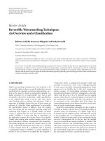
set-partitioning embedded block coder (SPECK) [10, 11],
originally developed as a 2D image coder, employs quadtree
partitioning (see Figure 4(a)) to locate significant coefficients
within a subband; a 3D extension (3D-SPECK [29, 30]) re-
places quadtrees with octrees as illustrated in Figure 4(b).
A similar approach is embodied by the binary set splitting
with k-d trees (BISK) algorithm in both its 2D (2D-BISK
[12]) and 3D (3D-BISK [3, 31]) variants wherein sets are
always partitioned into two subsets. An advantage of these
set-partitioning algorithms is that sets are confined to reside
within a single subband at all times throughout the algo-
rithm, whereas zerotrees span across multiple transform res-
olutions. Not only does this fact entail a simpler implementa-
tion, it is also beneficial from a computational standpoint as
the coder must buffer only a single subband at a given time,
leading to reduced dynamic memory needed [11]. Further-
more, the SPECK and BISK algorithms are easily applied to
both the dyadic and packet transform structures of Figures
1(b), 2(a),and2(b) with no algorithmic differences.
Another approach to within-subband coding is to em-
ploy extensively conditioned, multiple-context adaptive
arithmetic coding. JPEG2000 [13, 19, 32–34], the most
prominent conditional-coding technique, codes the signifi-
cance map of an image using the known significance states of
neighboring coefficients to provide the context for the cod-
ing of the significance state of the current coefficient. To code
a 2D image, a JPEG2000 encoder first performs a 2D wavelet
transform on the image and then partitions each transform
subband into small, 2D rectangular blocks called codeblocks,
which are typically of size 32
× 32 or 64 × 64 pixels. Subse-
quently, the JPEG2000 encoder independently generates an
embedded bitstream for each codeblock. To assemble the in-
dividual codeblock bitstreams into a single, final bitstream,
each codeblock bitstream is truncated in some fashion, and
the truncated bitstreams are concatenated together to form
the final bitstream.
J. E. Fowler and B. Pesquet-Popescu 5
(a)
(b)
Figure 4: Set partitioning. (a) 2D quadtree partitioning. (b) 3D oc-
tree partitioning.
In JPEG2000, the method for codeblock-bitstream trun-
cation is typically a Lagrangian rate-distortion optimal tech-
nique, post-compression rate-distortion (PCRD) optimization
[32, 35]. PCRD optimization is performed simultaneously
across all of the codeblocks from the image, producing an
optimal truncation point for each codeblock. The truncated
codeblocks are then concatenated together to form a single
bitstream. The PCRD optimization, in effect, distributes the
total rate for the image spatially across the codeblocks in
a rate-distortion-optimal fashion such that codeblocks with
higher energy, which tend to more heavily influence the dis-
tortion measure, tend to receive greater rate. Additionally, the
truncated codeblock bitstreams are interleaved in an opti-
mal order such that the final bitstream is close to being rate-
distortion optimal at many truncation points. As described
in Part 1 of the standard, JPEG2000 is, in essence, a 2D im-
age coder. However, for 3D imagery, the coding extensions
available in Part 2 of the standard can effectuate the packet
transform of Figure 2(a), and the PCRD optimization can
be applied across all three dimensions; this strategy for 3D
images has been called “JPEG2000 multicomponent” [36 ].
We note that JPEG2000 with truly 3D coding, consisting of
arithmetic coding of 3D codeblocks as in [37], is under de-
velopment as JPEG2000 Part 10 (JP3D), an extension to the
core JPEG2000 standard; however, the use of JPEG2000 mul-
ticomponent currently remains widespread for 3D imagery .
Thereaderisreferedto[33, 34] for useful introductions to
the JPEG2000 standard.
Figures 5 and 6 illustrate typical coding performance
for some of the prominent 2D and 3D wavelet-based image
coders discussed above. For 2D images, distortion is usually
measured as a peak signal-to-noise ratio (PSNR), defined as
PSNR
= 10 log
10
255
2
D
,(1)
where D is the mean square error (MSE) between the origi-
nal image and the reconstructed image; for 3D images, typ-
ically an SNR is used where 255
2
in (1) is replaced by the
26
28
30
32
34
36
PSNR (dB)
0.10.20.30.40.50.60.70.80.91
Rate (bpp)
JPEG-2000
SPIHT
SPECK
JPEG
Figure 5: Rate-distortion performance for the 2D “barbara” im-
age comparing the wavelet-based JPEG2000, SPIHT, and SPECK
coders, as well as the original JPEG standard [38, 39]. The Qc-
cPack [40]() implementations for
SPIHT and SPECK are used, while JPEG-2000 is Kakadu Ver. 5.1
() and JPEG is the Independent
JPEG Group implementation (). The wavelet-
based coders use a 5-stage wavelet decomposition with 9–7 wavelet
filters.
28
30
32
34
36
38
40
42
44
46
SNR (dB)
0.10.20.30.40.50.60.70.80.91
Rate (bpppb)
JPEG-2000
3D-SPIHT
3D-SPECK
Figure 6: Rate-distortion performance for the 3D image “moffett,”
an AVIRIS hyperspectral image of spatial size 512
× 512 with 224
spectral bands. A wavelet-packet transform with 9–7 wavelet filters
and 4 levels both spatially and spectrally is used. 3D-SPIHT uses
asymmetric zerotrees, and JPEG2000-multicomponent cross-band
rate allocation is used for JPEG2000.
6 EURASIP Journal on Image and Video Processing
(a) (b)
Figure 7: (a) Original scene. (b) Arbitrarily shaped image objects to be coded with shape-adaptive coding.
dataset variance. Both the PSNR and SNR have units of deci-
bels (dB). The bitrate is measured in terms of bits per pixel
(bpp) for 2D images and typically bits per voxel (bpv) for
3D imagery (equivalently bits per pixel per band (bpppb) for
hyperspectral imagery consisting of multiple spectral bands).
We see in Figures 5 and 6 that JPEG2000 offers performance
somewhat superior to that of the other techniques for both
2D and 3D coding.
In this special issue, the work “Adaptation of zerotrees
using signed binary digit representations for 3D image cod-
ing” by E. Christophe et al. presents a 3D zerotree-based
coder operating on hyperspectral imagery decomposed with
the packet transform of Figure 2(a). The 3D-EZW algorithm
is modified so as to eliminate the refinement pass (called
the “subordinate” pass in the context of EZW [8]). Elimi-
nating the subordinate pass, which typically entails a sorted
list, simplifies the algorithm implementation but decreases
coding efficiency. However, the use of a s igned-binary-digit
representation rather than the traditional sign-magnitude
form for the wavelet coefficients increases the proportion of
zero bits in the bitplanes, thereby increasing coding efficiency
back to equal the original 3D-EZW implementation. Also in
this special issue, “JPEG2000 compatible lossless coding of
floating-point data” by B. E. Usevitch proposes extensions to
the JPEG2000 standard to provide lossless coding of floating-
point data such as that arising in many scientific applications.
Several modifications to the JPEG2000 bitplane-coding pro-
cedure and context conditioning are made to accommodate
extended-integer representation of floating-point numbers.
2.1.3. Coding of arbitrarily shaped imagery
In traditional image processing—as is the case in the pre-
ceding discussion—it is implicitly assumed that imagery
has the shape of a rectangle (in 2D) or rectangular vol-
ume ( in 3D). The majority of image-coding literature ad-
dresses the coding of only rectangularly shaped imagery.
However, imagery with arbitrary, nonrectangular shape has
become important in a number of areas, including multi-
media communications (e.g., the arbitrarily shaped video
objects as covered by the MPEG-4 video-coding standard
[41] and other approaches [42–47]), geospatial imagery (e.g.,
oceanographic temperature datasets [3, 31, 48, 49], multi-
spectral/hyperspectral imagery [50, 51]), and biomedical ap-
plications (e.g., mammography [52], DNA microar ray im-
agery [53–55]). Shape-adaptive image coding for these appli-
cations is usually achieved by adapting existing image coders
designed for rectangular imagery to the shape-adaptive cod-
ing problem.
In a general sense, shape-adaptive coding can be consid-
ered to be the problem of coding an arbitrarily shaped im-
agery “object” residing in a typically rectangularly shaped
“scene” as illustrated in Figure 7. The goal is to code the im-
age object without expending any bits towards the nonob-
ject portions of the scene. Typically, an object “mask” will
be required to be transmitted to the decoder separ ately in
order to delineate the object from nonobject regions of the
scene. Below we focus on object coding alone, assuming that
any one of a number of lossless bilevel-image coding algo-
rithms is used to provide an efficient representation of this
binary object mask as side information to the central shape-
adaptive image-coding task. Likewise, the segmentation of
image objects from the nonobject background is considered
an application-specific issue outside the scope of the shape-
adaptive coding problem.
As discussed above, typical wavelet-based coders have
a common design built upon three major components—
a DWT, significance-map coding, and successive-approx-
imation quantization in the form of bitplane coding. Each of
these constituent processes is easily rendered shape adaptive
for the coding of an image object with arbitrary shape. Typ-
ically, a shape-adaptive DWT (SA-DWT) [42] is employed
such that only image pixels lying inside the object are trans-
formed into wavelet coefficients. Once in the wavelet do-
main, all regions corresponding to nonobject areas in the
original image are permanently considered “insignificant”
and play the same role as true insignificant coefficients in
significance-map coding. While most shape-adaptive coders
are based on this general idea, a number of approaches em-
ploy various modifications to the significance-map encoding
J. E. Fowler and B. Pesquet-Popescu 7
(such as explicitly discarding sets consisting of only nonob-
ject regions from further consideration [3, 12, 31, 43, 44]) to
increase performance. See [3]foracomprehensiveoverview
of wavelet-based shape-adaptive coders.
In this special issue, the work “Costs and advantages
of object-based image coding with shape-adaptive wavelet
transform” by M. Cagnazzo et al. examines sources of in-
efficiencies as well as sources of performance gains that re-
sult from the application of shape-adaptive coding. It is ob-
served that inefficiencies arise from both the reduced energy-
compaction capabilities of the SA-DWT (due to less data
for the DWT to process) as well as an interaction of the
significance-map coding with object boundaries (e.g., in
shape-adaptive SPIHT [43], zerotrees w hich overlap the ob-
ject/nonobject boundary). On the other hand, image ob-
jects tend to be more coherent and “smoother” than full-
frame imager y since object/nonobject boundary edges are
not present in the object, a characteristic that may lead to
coding gains. Experimental results in “Costs and advantages
of object-based image coding with shape-adaptive wavelet
transform” by M. Cagnazzo et al. provide insight as to the rel-
ative magnitude of these losses and gains as can be expected
in various operational conditions.
2.2. Video coding
The outstanding rate-distortion performance of the coders
described above has led to wavelets dominating the field
of still-image compression over the last decade. However,
such is not the case for wavelets in video coding. On the
contrary, the traditional architecture (illustrated in Figure 8)
consisting of a feedback loop of block-based motion estima-
tion (ME) and motion compensation (MC) followed by a dis-
cretecosinetransform(DCT) of the residual is still widely em-
ployed in modern video-compression systems and an inte-
gral part of standards such as MPEG-2 [59], MPEG-4 [41],
and H.264/AVC [60]. However, there has naturally been great
interest in carrying over the gains seen by wavelet-based
still-image coders into the video realm, and several differ-
ent approaches have been proposed. The first, and most
straightforward, is essentially an adaptation of the traditional
ME/MC feedback architecture to the use of a DWT, employ-
ing a redundant transform to provide the shift invariance
necessary to the wavelet-domain ME/MC process. A second
approach involves eliminating the feedback loop of the tra-
ditional architecture by applying ME/MC in an “open-loop”
manner to drive a temporal wavelet filter. Finally, a recent
strategy proposes eliminating explicit ME/MC altogether and
instead rely ing on the greater directional sensitivities of a 3D
complex wavelet transform to represent the motion of sig-
nal features. Table 2 overviews each of the these recent ap-
proaches to wavelet-based video coding, and we discuss each
one in detail below.
2.2.1. Redundant transforms and video coding
Perhaps the most straightforward approach to wavelet-based
video coding is to simply replace the DCT with a DWT in
the traditional architecture of Figure 8, thereby performing
ME/MC in the spatial domain and calculating a DWT on the
resulting residual image (e.g., [61]). This simple approach
suffers from blocking artifacts [62], which a re exacerbated
if the DWT is not block based but rather the usual whole-
image transform. An alternative paradigm would be to have
ME/MC take place in the wavelet domain (e.g., [63]). How-
ever, the fact that the critically sampled DWT used ubiqui-
tously in image-compression efforts is shift variant has long
hindered the ME/MC process in the wavelet domain [64, 65].
It was recognized in [56, 66, 67] that difficulties asso-
ciated with the shift var iance of traditional DWTs could be
overcome by choosing instead to perform ME/MC in the do-
main of a redundant transform. In essence, the redundant
DWT (RDWT)
2
[69–71] removes the downsampling oper-
ation from the traditional DWT to ensure shift invariance at
the cost of a redundant, or overcomplete, representation.
There are several equivalent ways to implement the
RDWT, and several ways to represent the resulting over-
complete set of coefficients. The most popular coefficient-
representation scheme employed in RDWT-based video
coders is that of a coefficient tree. This tree representation
is created by employing filtering and downsampling as in the
usual critically sampled DWT; however, all sets, or phases,
of downsampled coefficients are retained and arranged in
a tree-like fashion. The RDWT was originally formulated,
however, as the algorithme
`
atrousimplementation [69, 70].
In this implementation, decimation following wavelet filter-
ing is eliminated, and, for each successive scale of decompo-
sition, the filter sequences themselves are upsampled, creat-
ing “holes” of zeros between nonzero filter taps. As a result,
the size of each subband resulting from an RDWT decom-
position is exactly the same as that of the input signal, as is
illustrated for a 2D image in Figure 9. By appropriately sub-
sampling each subband of an RDWT, one can produce ex-
actly the same coefficients as does a critically sampled DWT
applied to the same input signal.
The majority of a prior work concerning RDWT-based
video coding originates in the work of Park and Kim [56],
in which the system shown in Figure 10 was proposed. In
essence, the system of Figure 10 works as fol lows. An input
frame is decomposed with a critically sampled DWT and
partitioned into cross-subband blocks, w herein each block is
composed of the coefficients from each subband that corre-
spond to the same spatial block in the or iginal image. A full-
search block-matching algorithm is used to compute motion
vectors for each wavelet-domain block; the system uses as the
reference for this search an RDWT decomposition of the pre-
vious reconstructed frame, thereby capitalizing on the shift
invariance of the redundant transform. Any of the 2D image
coders described above in Section 2.1.2 is then used to code
the MC residual. Subsequent work has offered refinements
to the system depicted in Figure 10, such as the deriving
of motion vectors for each subband [72, 73], or resolution
2
There are several names that have been given to this transform, including
the overcomplete DWT (ODWT) and the undecimated DWT (UDWT)—
our use of the RDWT moniker is from [68].
8 EURASIP Journal on Image and Video Processing
Input image
sequence
+
−
DCT CODEC
Output bitstream
CODEC
−1
DCT
−1
+
+
z
−1
Motion
compensation
Motion
estimation
Motion vectors
Figure 8: The t raditional video-coding system consisting of ME/MC followed by DCT. z
−1
= frame delay, CODEC isany2Dstill-image
coder.
Table 2: Strategies for wavelet-based video coding.
Strategy Prominent examples Methodology Notes
Wavelet-based hybrid coding Park and Kim [56]
ME/MC in wavelet domain
via shift-invariant RDWT
MCTF
MC-EZBC [57]
Temporal transform eliminates
ME/MC feedback loop
Performance competitive with
traditional coders (H.264); full
scalability
Complex wavelet transforms
[58]
Directionality of transform
eliminates ME/MC
Performance between that of 3D
still-image coding and traditional
hybrid coding; no ME/MC
B
2
V
2
H
2
D
2
V
1
H
1
D
1
Figure 9: Spatially coherent representation of a two-scale RDWT of
a2Dimage.Coefficients retain their correct spatial location within
each subband, and each subband is the same size as the original
image. B
j
, H
j
, V
j
,andD
j
denote the baseband, horizontal, vertical,
and diagonal subbands, respectively, at scale j.
[74], independently; subpixel accuracy ME [75, 76]; and
resolution-scalable coding [73, 74, 77].
In most of the RDWT-based video-coding systems de-
scribed above, the redundancy inherent in the RDWT is used
exclusively to permit ME/MC in the wavelet domain by over-
coming the well-known shift variance of the critically sam-
pled DWT. However, the RDWT redundancy can be put to
greater use, as was demonstrated in [81, 82], wherein the re-
dundancy of the RDWT is used to guide mesh-based ME/MC
via a cross-subband correlation operator, and in [83, 84],
wherein the transform redundancy is employed to yield mul-
tiple predictions diverse in transform phase that are com-
bined into a single multihypothesis prediction.
2.2.2. Motion-compensated temporal filtering (MCTF)
Given the fact that wavelets are inherently suited to scalable
coding, it is perhaps natural that the most widespread use
of wavelets in video has occurred in conjunction with efforts
to produce coders with a high degree of spatial, temporal,
and fidelity scalability. It is thought that such scalability will
be useful in numerous v ideo-based communication applica-
tions, allowing a heterogeneous mix of receivers with varying
capabilities to receive a single video signal, decoding at the
spatial resolution, frame rate, and quality appropriate to the
receiving device at hand. However, it has been generally rec-
ognized that the goal of highly scalable video representation
J. E. Fowler and B. Pesquet-Popescu 9
Input image
sequence
DWT
+
−
CODEC
Output bitstream
CODEC
−1
+
+
DWT
−1
z
−1
Motion
compensation
Motion
estimation
RDWT
Motion vectors
Figure 10: The RDWT-based video coder of [56]. z
−1
= frame delay, CODEC is any still-image coder operating in the critically sampled-
DWT domain as described in Section 2.1.2. The cascade of the inverse DWT and forward RDWT in the feedback loop can be computationally
simplified by using a complete-to-overcomplete transform [78–80].
Current frame
(a)
Reference frame
Unconnected pixels
(b)
Figure 11: In MCTF using block matching, blocks in the reference frame corresponding to those in the current frame typically overlap.
Thus, some pixels in the reference frame are mapped several times into the current frame while other pixels have no mapping. These latter
pixels are “unconnected.”
is fundamentally at odds with the traditional ME/MC feed-
back loop (such as in Figures 8 and 10) which hinders the
achieving of a high deg ree of scalability. Consequently, 3D
transforms, which break the ME/MC feedback loop, are a
primary focus in efforts to provide full scalability. However,
the deploying of a t ransform in the temporal direction with-
out MC typically produces low-quality temporal subbands
with significant “ghosting” artifacts [85] and decreased cod-
ing efficiency. Consequently, there has been significant in-
terest in motion-compensated temporal filtering (MCTF) in
which it is attempted to have the temporal transform follow
motion trajectories. Below, we briefly overview MCTF and
its recent use in wavelet-based video coding; for a more thor-
ough introduction, see [86, 87].
Many approaches to MCTF follow earlier works [88,
89] which adapted block-based ME/MC to the temporal-
transform setting, that is, video frames are divided into
blocks, and motion vectors of the blocks in the current frame
point to the closest matching blocks in the preceding ref-
erence frame. If there is no motion, or there is only pure
translational motion, the motion vectors provide a one-to-
one mapping between pixels in the reference fr ame and pix-
els in the current frame. This one-to-one mapping between
frames then provides the trajectory for filtering in the tem-
poral direction for MCTF. However, in more realistic video
sequences, motion is usually much more complex, yield-
ing one-to-many mappings for some pixels in the reference
frame and no mapping for others, such as illustrated in
10 EURASIP Journal on Image and Video Processing
Figure 11. These latter pixels are thus “unconnected” and are
handled in a typically ad hoc manner outside of the temporal-
filtering process, while a single temporal path is chosen for
multiconnected pixels typically based on raster-scan order.
It has been recognized that a lifting
3
implementation
[90, 91] permits the MC process in the temporal filtering
to be quite general and complex while remaining easily in-
verted. For example, let x
1
(m, n)andx
2
(m, n)betwoconsec-
utive frames of a video sequence, and let W
i, j
denote the op-
erator that maps frame i onto the coordinate system of frame
j through the particular MC scheme of choice. Ideally, we
would want W
1,2
[x
1
](m, n) ≈ x
2
(m, n). Haar-based MCTF
would then be implemented via lifting as
h(m, n)
=
1
2
x
2
(m, n) − W
1,2
x
1
(m, n)
,
l(m, n)
= x
1
(m, n)+W
2,1
[h](m, n),
(2)
where l(m, n)andh(m, n) are the lowpass and highpass
frames, respectively, of the temporal transform [91]. This
formulation, illustrated in Figure 12, permits any MC to be
used since the lifting decomposition is trivially inverted as
x
1
(m, n) = l(m, n) − W
2,1
[h](m, n),
x
2
(m, n) = 2h(m, n)+W
1,2
x
1
(m, n).
(3)
The lifting implementation of the temporal filtering facil-
itates temporal filters longer than the Haar [91–93], sub-
pixel accuracy for ME [57, 90, 91, 94–96], bidirectional MC
and multiple reference frames [57, 96, 97], multihypothe-
sis MC [98–101], ME/MC using meshes rather than blocks
[85, 95, 100, 101], and multiple-band schemes that increase
temporal scalability [102–104].
For coding, MCTF is combined with a 2D spatial DWT,
and typically one of the 3D coders described in Section 2.1.2,
such as 3D-SPIHT or JPEG2000 multicomponent, is applied
to render the final bitstream. In the absence of MC, the
temporal transform would be applied separately from the
spatial transform, resulting in the packet decomposition of
Figure 2(a). In such a case, the order in which the tempo-
ral and spatial transforms were performed would not matter.
However, due to the shift invariance of the spatial DWT in
the presence of MC, the temporal and spatial transforms do
not commute, giving rise to two broad families of MCTF ar-
chitectures.
Most MCTF-based coders apply MCTF first on spatial-
domain fr ames, following with a spatial 2D dyadic DWT.
Such “t +2D” coders have the architecture illustrated in
Figure 13(a). A number of prominent MCTF-based coders
(e.g., [57, 88–98, 105]) employ the t+2D architecture, includ-
ing the prominent MC-EZBC coder [57]—currently largely
considered to be the state-of-the-art in wavelet-based MCTF
scalable coding—and its refinements [105–107]. Alterna-
tively, one can reverse the transform order, applying the spa-
tial transform first, and then conducting temporal filtering
3
See Section 2.3 for more on lifting in general.
Video sequence
Motion compensation
Lowpass temporal filtering
Highpass temporal filtering
Temporal-lowpass frames
Temporal-highpass frames
Figure 12: Haar-based MCTF, depicting three levels of temporal
decomposition.
among wavelet-domain frames. Such “2D+t”coders[76, 99–
101, 108–111] typically apply MCTF within each subband
(or resolution) independently as illustrated in Figure 13(b);a
spatial RDWT such as described in Section 2.2.1 is often used
to provide shift invariance for the wavelet-domain MCTF. Fi-
nally, a hybrid “2D + t +2D”architecturewasproposedin
[86, 112, 113] to continuously adapt between the t +2D and
2D + t structures to reduce motion artifacts under both tem-
poral and spatial scaling.
We note that the forthcoming extension to H.264/AVC
for scalable video coding [114, 115] uses open-loop ME/MC
for temporal scalability and is closely related in this sense
to MCTF. However, the remainder of the coder follows a
more traditional layered approach to scalability with an
H.264/AVC-compatible base layer. An oversampled pyramid,
rather than a spatial DWT, is used for spatial scalability.
In this special issue, it is recognized in “Quality variation
control for three-dimensional wavelet-based video coders”
by V. Seran and L. P. Kondi that different temporal-filter syn-
thesis gains between even and odd frames lead to fluctuations
in quality from frame to frame in the reconstructed video
sequence for both the t +2D and 2D + t MCTF architec-
tures. Two approaches are proposed in the same paper for
dealing with the temporal quality variation: a rate-control
algorithm that sets appropriate priorities for the temporal
subbands as well as an approach to modify the filter coeffi-
cients directly to compensate for the fluctuation. Also in this
issue, a t+2D coder that produces a JPEG2000 bitstream (us-
ing the Part 3 [116], “motion JPEG2000,” component of the
J. E. Fowler and B. Pesquet-Popescu 11
Input
sequence
Tem po ral
filtering
Spatial
DWT
3D coder
Output
bitstream
Motion
estimation
Motion
vectors
(a)
Input
sequence
Spatial
DWT
Subband 1
Subband 2
Subband 3
Subband N
MCTF
MCTF
MCTF
MCTF
.
.
.
3D coder
Output
bitstream
(b)
Figure 13: (a) The t +2D MCTF architecture. (b) The 2D + t MCTF architecture, with “in band” MCTF applied individually on each spatial
subband. “3D coder” indicates any of the 3D wavelet-based coders from Section 2.1.2.
standard) is proposed in [117]. In this coder, a model-based
bit-allocation procedure is designed to yield a high degree of
scalability.
2.2.3. Complex wavelet transforms
Although MCTF as discussed above is a relatively recent in-
novation, the concept of coding v ideo by grouping several
frames together into a 3D volume and employing transforms
in the spatial and temporal directions has been explored on
and off in the literature for the past several decades—an early
wavelet-based example is [118]. However, temporal trans-
forms for video pose a unique problem that causes 3D video
coding to be different from the coding of other 3D data types;
MCTF is just one approach to temporally decorrelating ob-
ject pixels regardless of the frame-to-frame motion they un-
dergo. An alternative to MCTF has arisen recently in the form
of the complex dual-tree discrete wavelet transform (DDWT)
[119–121]. The DDWT is a redundant transform that, in the
3D case [121], produces four times as many subbands as the
DWT , with each subband oriented in a different spatiotem-
poral direction. When applied to a video signal, these ori-
entations help isolate image features moving in different di-
rections, providing inherent motion selectivity. The ability of
the transform to describe motion without explicit ME/MC
has motivated the use of the DDWT in video-coding sys-
tems [58, 122] looking to avoid the computational complex-
ity associated with ME. However, since the 3D DDWT is
four times redundant, efficient coding of the transform co-
efficients is a challenging task.
In this special issue, “Video coding using 3D dual-tree
wavelet transform” by B. Wang et al. as well as in preceding
work [58], a DDWT-based video coder is proposed to exploit
the fact that a significant degree of correlation exists between
DDWT coefficients residing at the same spatiotemporal loca-
tions in different subbands. Twenty-eight-dimensional cross-
subband vectors of DDWT coefficients assembled from the
28 highpass DDWT subbands are assembled and coded with
arithmetic coding resulting in rate-distortion performance
superior to that of 3D-SPIHT [22, 23] applied directly to
a 3D DWT of the video sequence with no ME or MC. In
[124], it is further recognized that large-magnitude DDWT
coefficients occur rather sparsely such that small or zero
coefficients tend to form spatiotemporally coherent regions
within each subband. A coder is then proposed which com-
bines the BISK algorithm [3, 12, 31], the packet transform
of Figure 2(b), and 4-dimensional cross-subband vectors of
DDWT coefficients.
2.3. Image-adaptive lifting transforms
The 2D and 3D image coders discussed above rely on the
DWT applied to the image data to result in coefficients hav-
ing, more or less, the properties outlined at the start of
Section 2.1.2. Although traditional DWTs do a reasonably
good job at this task, there have been a number of efforts to
improve wavelet decompositions by abandoning their fixed
structure in favor of transforms that adapt to local signal
characteristics. For this, an alternative transform implemen-
tation is essential.
DWTs have long been understood, and implemented, in
terms of filter banks, and several early approaches at signal-
adaptive transforms proposed nonstationary filter-based de-
compositions (e.g., [125, 126
]). However, recent use has
favored implementations based on lifting [123, 127]. It is
well known that any biorthogonal DWT can be factored
12 EURASIP Journal on Image and Video Processing
Input
signal
Highpass
subband
Lowpass
subband
+
−
LWT Prediction Update
+
+
Odd samples
Even samples
(a)
Output
signal
Highpass
subband
Lowpass
subband
+
+
LWT
−1
PredictionUpdate
−
+
Odd samples
Even samples
(b)
Figure 14: A 1D DWT implemented via lifting. (a) The forward transform (analysis). (b) The inverse transform (synthesis). LWT is a
polyphase decomposition of the input signal into even-indexed and odd-indexed samples (the “lazy wavelet transform” [123]).
into a sequence of lifting steps, typically resulting in an im-
plementation with computational complexity significantly
reduced as compared to the traditional convolution-based
filter-bank implementation [128]. This fact alone would ac-
count for widespread use in practical DWT implementa-
tions; however, the lifting structure, depicted in Figure 14,
permits a number of interesting generalizations to the DWT
via suitably modifying the prediction or update operators.
Such “second-generation” wavelet constructs include bound-
ary wavelets, wavelets on irregular sampling, and wavelets
that map integers to integers [17, 18]; see [129]foranexten-
sive overview of both first- and second-generation wavelets
based on lifting.
The key to second-generation lifting formulations is that
the inverse transform is trivially effectuated by simply revers-
ing the operations of the forward transform, as illustrated in
Figure 14(b). This fact has been exploited recently in order to
devise transforms that adapt to local signal features by modi-
fying the prediction or update operations in response to local
signal characteristics [130–146]. In these schemes, as long as
the inverse transform can track the prediction/update vari-
ations made by the forward transform, perfect reconstruc-
tion is assured. Such signal-adaptive transforms clearly lack
shift invariance and are typically nonlinear, but often pro-
duce subband signals that can be better exploited in appli-
cations. Of primary interest are schemes that permit adap-
tion to take place without the need for “side information”
between the forward and inverse tr a nsforms. Although ex-
plicitly describing the adaption decisions made at the for-
ward tr ansform permits easy implementation of the inverse
transform, the side information results in a transform that is,
in essence, no longer critically sampled but, rather, overcom-
plete.
The most common approach to adaptive lifting is based
on the idea that highpass DWT subbands should be rela-
tively sparse to be beneficial in most applications. As a con-
sequence, the usual strategy is to design the prediction oper-
ator to adapt to the signal locally so as to minimize the en-
ergy in the resulting highpass subband. The update step, on
the other hand, usually remains fixed, typically set to the up-
date operator for some first-generation biorthogonal trans-
form, such as that of the 5/3 DWT. This adaptive-prediction
lifting strategy, employed in [130–136, 146], is illustrated in
Figure 15.Alternatively,in[137–145], the opposite approach
of an adaptive update operator plus fixed prediction is pur-
sued; in this adaptive-update case, a large signal gradient pro-
duces a “weak” update step such that edges and other sharp
signal features are not smoothed but retain their sharpness.
In order to permit trivial transform inversion of an
adaptive-lifting scheme, the adaptive operator must operate
on the same polyphase signal component as is used to drive
the adaption of the operator itself. For example, as shown in
J. E. Fowler and B. Pesquet-Popescu 13
Input
signal
Highpass
subband
Lowpass
subband
+
−
LWT
Predictor
calculation
Prediction Update
+
+
Odd samples
Even samples
Figure 15: Adaptive-prediction lifting. Predictor is adapted to local signal features, usually in an effort to minimize energy in the highpass
subband.
Figure 15, the adaption of the predictor operator is driven by
the even polyphase component, and the predictor produces
its prediction from the same even samples. In this manner,
the predicted values, as well as the predictor itself, can be de-
termined within the inverse t ransform. Most adaptive-lifting
schemes follow this polyphase-based approach. However, the
adaption of the predictor in [135, 136] is driven from the
highpass subband (the opposite polyphase component); this
adaption is based causally on already processed highpass co-
efficients such that the inverse transform can produce the
same adaption. Additionally, the adaption of the update op-
erator in [137–145] is driven from both polyphase compo-
nents; in this case, the adaption is carefully designed mathe-
matically to ensure perfect reconstruction.
In any case, the key to inversion of an adaptive lifting
transform is having the inverse produce the same adaptive
operator as did the forward transform. Clearly, any signal-
processing operations—in particular, quantization—that lie
between the forward transform and its inverse can jeopar-
dize the ability to track the adaption of the operator in ques-
tion. As a consequence, much of the prior literature considers
only the application of lossless compression in conjunction
with adaptive lifting (e.g., [132, 133, 144, 146]). On the other
hand, lossy compression can be considered if one is mindful
of the consequences that quantization can entail within the
adaption process of the inverse transform. For example, in
[130, 131 ], the adaptive-prediction step follows the fixed up-
date step (contrary to the architecture of Figure 15), and the
adaption of the predictor is driven by quantized signal values;
in [135], quantization is applied within the feedback loop of
the causal highpass prediction update; and, in [142, 143, 145]
conditions are determined for recovering the original adap-
tion decisions at the inverse transform, and a relation be-
tween the reconstruction error and the quantization error is
derived.
To this point, we have considered issues surrounding
adaptive lifting of 1D signals. For 2D imagery, the typical
approach is to apply a 1D adaptive-lifting scheme such as
depicted in Figure 15 separably to the rows and columns of
the image. The 1D-based strategy can be further refined for
2D coding by enlarging the prediction (or update) context
to include samples for rows/columns other than the current
one [130, 131, 135, 136]. Alternatively, a quincunx subsam-
Figure 16: Quincunx subsampling. The two shades of gray indicate
thetwopolyphasecomponents.
pling scheme (see Figure 16) permits lifting to be applied in
a nonseparable fashion directly in 2D [133, 146–149]; in this
case, each lifting stage produces a sing le lowpass and a single
highpass subband rather than the four directional subbands
that arise in a separable DWT. Finally, the four directional
subbands of the separable decomposition can be produced
simultaneously via a single update operator combined with
three prediction operators [138].
In this special issue, the work “Block-based adaptive vec-
tor lifting schemes for multichannel image coding” by A.
Benazza-Benyahia et al. proposes a vector-valued adaptive-
lifting scheme in which a predictor is adapted on a block-
by-block basis to the signal within quincunx-based lifting.
Although the transform is overcomplete in that prediction-
adaption decisions are explicitly transmitted to the inverse
transform, the adaption decisions are conveyed simultane-
ously with the quadtree-based coding of the transfor m coeffi-
cients. In “An edge-sensing predictor in wavelet lifting str uc-
tures for lossless image coding” by
¨
O. N. Gerek and A. E.
C¸ etin, an adaptive prediction is designed in order to detect
edge orientation and to form predictions accordingly; a 2D
window is employed to determine edge orientation. Finally,
in [150], the adaptive image-interpolation scheme of [151]
is used as the basis of adaptive predictors and updates for
14 EURASIP Journal on Image and Video Processing
Low-resolution
input signal
Prediction
2
2
DWT synthesis stage
Highpass
synthesis
filter
Lowpass
synthesis
filter
High-resolution
output signal
Figure 17: Wavelet-based interpolation of a 1D signal. 2D image interpolation may be accomplished by a similar system applied to the
subbands of a 2D DWT synthesis stage, or by applying this 1D system in a separable fashion to image rows and columns independently.
lifting, and an application to lossless image compression is
considered.
2.4. Image interpolation
Although wavelets have perhaps played their most promi-
nent role in source-coding applications such as the image and
video coders described above, wavelet-based signal represen-
tations are widely used in other applications, such as signal
filtering, denoising, feature detection, and signal enhance-
ment. In particular, the multiresolution char acteristic inher-
ent to wavelet transforms makes them a natural choice for
the task of image interpolation—the magnification or res-
olution enhancement of an image with the goal of no loss
to the sharpness of the image. The philosophy fundamen-
tal to wavelet-based image interpolation is illustrated in 1D
in Figure 17. Essentially, a highpass subband is synthesized
by a prediction process from the given low-resolution signal
which is, itself, treated as a lowpass subband. Both subbands
then undergo a single stage of DWT synthesis, resulting in a
high-resolution signal magnified by a factor of 2 as compared
to the original input signal.
Although image interpolation is a classic problem in the
field of image processing, traditional solutions such as bilin-
ear or bicubic interpolation impose a constraint on conti-
nuity in the image, resulting in a tendency to produce over-
smoothed edges [152]. Additionally, these traditional inter-
polators include the original image pixels in the interpolated
output image, essentially making an inherent assumption
that the original low-resolution input image was produced by
direct downsampling of some higher-resolution image. Yet,
antialiasing filters are often used in practice in image acqui-
sition or resolution reduction [152]. On the other hand, the
inclusion of the lowpass synthesis filter in Figure 17 can be
seen as compensating for the antialiasing filter (which would
be the lowpass analysis filter in a nonexistent DWT analysis
stage), while the predictor in Figure 17 explicitly adds high-
frequency information to retain sharp edge and texture de-
tails.
Many wavelet-based interpolation schemes are based on
the techniques originating in [153–155]. In these algor ithms,
a 1D RDWT (see Section 2.2.1) is used to determine edge lo-
cations in an image row or column by identifying signal fea-
tures that persist across wavelet scales in accordance with the
theory of [156]. The highpass band is then synthesized by
“copying” signal features from a lower-resolution subband
into the new highpass band at the locations of the identified
edges. The regularity of the edges is preserved by measuring
the decay in regularity across scales at the edge locations and
extrapolating into the newly created highpass subband. This
basic strategy has been enhanced by projection onto con-
vex sets (POCS, e.g., [157]) to iteratively refine the initial
extrapolated highpass band [153, 154 ]. Additionally, alter-
native strategies for producing the highpass prediction were
proposed in the form of linear minimum mean square esti-
mation [152], hidden Markov models [158], hidden Markov
trees [159], and Gaussian mixture models [160].
In this special issue, the work “Image resolution en-
hancement via data-driven parametric models in the wavelet
space” by X. Li adopts a POCS strategy consisting of an ob-
servational constraint (DWT analysis applied to the high-
resolution interpolator output must match the original low-
resolution input) as well as several additional constraints
on sharp highpass signal features. Specifically, separate con-
straints are formulated for edges, contours, and texture fea-
tures.
3. WAVELETS IN COMMUNICATIONS
AND NETWORKING
In a typical communication scheme, the output of a source
coder must be protected against errors caused by chan-
nel noise. Traditionally, this protection is accomplished by
adding redundancy to the output of the source coder through
channel coding, that is, via some form of error-correcting
code. The traditional paradigm is to conduct the design of
the source and channel coders s eparately from each other,
concatenating the two once they have been independently
optimized. However, it turns out that the overall concate-
nated system is typically optimal only under idealized con-
ditions. As a consequence, several alternative strategies have
arisen for producing the added redundancy necessary for
J. E. Fowler and B. Pesquet-Popescu 15
error-resilient communication, and wavelets have played a
role in a number of them. Below, we survey the use of
wavelets in the communication and networked transmission
of images and video. First, in Section 3.1,weoverviewpro-
cedures that produce redundancy by creating multiple corre-
lated codings, or descriptions, of the imagery for transmis-
sion across separate network paths. Then, in Section 3.2,we
overview techniques that dispense with the assumption of
the separability of the source and channel design problems
to develop systems in which the source and channel coders
are jointly designed.
3.1. Multiple-description coding
With increasing use of the Internet and other best-effort net-
works for multimedia communication, there is a growing
need for reliable transmission. Traditional research efforts
have concentrated on enhancing existing error-correction
techniques; however, recent years have seen an alternative so-
lution emerge and garner increasing attention. This latter so-
lution focuses mainly on the situation in which immediate
data retransmission is either impossible (e.g., network con-
gestion or broadcast applications) or undesirable (e.g., con-
versational applications with very low delay requirements).
We are referring to a specific technique known as multiple-
description coding (MDC). In this section, we overview the
use of wavelets in MDC; the reader is referred to [161]fora
comprehensive general review of MDC.
In essence, the MDC technique operates as illustr a ted in
Figure 18. The MDC encoder produces several correlated—
but independently decodable—bitstreams called descriptions.
The multiple descriptions, each of which preferably has
equivalent quality, are sent over as many independent chan-
nels to an MDC decoder consisting of a central decoder as
well as multiple side decoders. Each of the side decoders is
capable of decoding its corresponding description indepen-
dently of the other descriptions, producing a representation
of the source with some level of minimally acceptable qual-
ity. On the other hand, the central decoder can jointly decode
multiple descriptions to produce the best-quality reconstruc-
tion of the source. In the simplest scenario, the transmission
channels are assumed to operate in a binary fashion; that is, if
an error occurs in a given channel, that channel is considered
damaged, and the entirety of the corresponding bitstream is
considered unusable at the receiving end.
The success of an MDC technique hinges on path diver-
sity, which balances network load and reduces the probability
of congestion. Typically, some amount of redundancy must
be introduced at the source level in order that an acceptable
reconstruction can be achieved from any of the descriptions,
and such that reconstruction quality is enhanced with ev-
ery description received. An issue of concern is the amount
of redundancy introduced by the MDC representation with
respect to a single-description coding, since there exists a
tradeoff between this redundancy and the resulting distor-
tion. Therefore, a great deal of effort has been spent on an-
alyzing the performance achievable with M DC ever since its
beginnings [162, 163] up until recently, for example, [164].
As an example of MDC, consider a wireless network in
which a mobile receptor can benefit from multiple descrip-
tions if they arrive independently, for example, on two neigh-
boring access points. In this case, when moving between
these two access points, the receiver might capture one or the
other access point, and, in some cases, both. Another way
to take advantage of MDC in a wireless environment is by
splitting the transmission in frequency to form the two de-
scriptions. For example, a laptop may be equipped with two
wireless cards (e.g., 802.11a and g) with each wireless card
receiving a different description. Depending on the dynamic
changes in the number of clients in each network, one wire-
less card may become overloaded, and the corresponding de-
scription may not be transmitted. In wired networks, differ-
ent descriptions can be routed to a receiver through differ-
ent paths by incorporating this information into the packet
header [165]. In this situation, the initial scenario of binary
“on/off ” channels might no longer be of interest. For ex-
ample, in a typical CIF-format video sequence, one fra me
might be encoded into several packets. In such cases, the
system should be designed to take into consideration indi-
vidual or bursty packet losses rather than a whole descrip-
tion.
Practical approaches to MDC include scalar quantization
[166–168], polyphase decompositions [169, 170], correlating
transforms [171–177], and frame expansions [178–180]. We
overview each of these strategies in the next sections below,
first in the context of wavelet-based MDC for still images be-
fore turning attention to MDC for video to conclude this sec-
tion.
3.1.1. Multiple-description scalar quantization
Multiple-description scalar quantization (MDSQ) [166]
consists of encoding a memoryless stationary zero-mean
source using a separate scalar quantizer for each descr iption.
The dictionaries of the scalar quantizers are determined from
the minimization of the central distortion, subject to a max-
imal admissible distortion on the side distortions. Once the
dictionaries are found, they must be indexed. In [166], two
types of indexing are described: nested index assignment and
linear index assignment. When one takes into account the
rate on the two channels in addition to the distortion, the
optimization problem is slightly different—in this case, the
central distortion is minimized under rate as well as distor-
tion constraints for the side decoders. Entropy coders follow
the quantizers, and the system is called entropy-constrained
MDSQ (ECMDSQ) [167]. An extension of the previous
results to vectors was provided in [
181–184] in the form of
multiple-description lattice vector quantization.
In this special issue, the work “Scalable multiple-
description image coding based on embedded quantization”
by A. I. Gavrilescu et al. describes an embedded MDSQ
which takes into account variations in the channel packet-
loss rate to yield an adaptive bitrate allocation. This embed-
ded MDSQ is applied to both still-image as well as video
coders.
16 EURASIP Journal on Image and Video Processing
Source
signal
Encoder
Description 1
Description 2
MDC decoder
Side
decoder 1
Central
decoder
Side
decoder 2
Acceptable
quality
Best
quality
Acceptable
quality
Figure 18: MDC with two descriptions.
3.1.2. Polyphase decompositions
A polyphase decomposition provides a straightforward and
relatively simple approach to achieve MDC—one first splits
the source samples into polyphase components (e.g., even
and odd samples) and then encodes the polyphase compo-
nents independently. Recall that the M polyphase compo-
nents of a source x[n] are the signals y
1
[n], y
2
[n], , y
M
[n]
such that
y
i
[n] = x[Mn + i], n ∈ Z, i ∈{1, , M}. (4)
In the polyphase approach to MDC, each description con-
sists of a single polyphase component, and, at the decoder
side, the correlation between the components is exploited to
recover any lost data.
This straightforward polyphase-based MDC strategy is
refined slightly in [169] wherein, after polyphase decomposi-
tion, redundancy is introduced in each description by adding
a low-rate version of the other polyphase components. As
a consequence, each description involves a main polyphase
component, encoded at high resolution, and several sec-
ondary polyphase components, encoded with less rate. The
decoder simply merges the received polyphase components,
and, if several versions of a given polyphase component are
received, the decoder makes use of only the one encoded at
the highest precision. For efficient coding, the polyphase sig-
nals must be decorrelated; if not, the decoder will be subop-
timal, since it does not exploit the existing correlation. This
system is therefore intended to be used after an initial source-
coding step which consists of decorrelating the input data
(e.g., a DWT or DCT).
For imagery, polyphase decompositions can be applied
to different types of information in the image—pixels in the
spatial domain, coefficientsofa2DDWT,orevenzerotreesof
wavelet coefficients (see Section 2.1.2). In this latter scheme,
odd and even zerotrees are split into two descriptions and
encoded as main and secondary components using SPIHT
[169, 170].
It is useful to note that, whereas in most other MDC sys-
tems, redundancy between the descriptions is controlled only
implicitly in the generation of the descriptions themselves,
the polyphase-based MDC of [169] explicitly separates gen-
eration of the descriptions from the addition of redundancy;
specifically, redundancy is controlled through the bitrate al-
located to the secondary components. Thus, we find, in a
certain sense, a separation principle between source cod-
ing (main quantization) and channel coding (added redun-
dancy). While traditional source coding relies on a transform
to reduce correlation between original-data (image) samples,
MDC consists of the introduction of correlation in order
to control redundancy in the transmitted bitstream. Below,
we consider two types of correlation for the wavelet-based
MDC of images—statistical correlation, through correlating
transforms; and deterministic correlation, through projec-
tion onto frames.
In this special issue, the work “Multiple description cod-
ing with redundant expansions and application to image
communications” by I. Radulovic and P. Frossard enters into
the general polyphase MDC category. In the coder proposed
in that work, a generic redundant dictionary is partitioned
such that different, yet correlated, dictionary “atoms” are put
into different descriptions.
3.1.3. Correlating transforms
A multiple-description correlating transform (MDCT) con-
sists of transforming a block of N centered, independent
Gaussian random variables into a block of N correlated vari-
ables. MDCT was introduced in [171, 172] for the case of
N
= 2 variables and generalized in [174, 175]toN>2vari-
ables. In [175], it was shown that performing quantization
after a linear continuous-valued transform T led to a distor-
tion significantly higher than when transform and quantiza-
tion are performed in the reverse order. This is due to the fact
that the quantization of Tx, x
= [
x
1
x
2
]
T
,isequivalenttoa
trellis-coded quantization of vector x in a trellis whose cells
are not square, which is suboptimal. The idea is therefore
to look for an optimal discrete-valued transform
T(x)(to
be applied to quantized vectors of the input source). For an
equal probability of failure on the two channels, it is shown
J. E. Fowler and B. Pesquet-Popescu 17
in [175] that the optimal continuous-valued transform has
the form
T
=
α (2α)
−1
−α (2α)
−1
,(5)
where the parameter α
∈ [
σ
2
/2σ
1
, ∞) allows tuning the re-
dundancy, ρ,
ρ
=
1
2
log
α
2
σ
2
1
+ σ
2
2
/
4α
2
σ
1
σ
2
,(6)
where σ
2
1
and σ
2
2
are the variances of the two sources. The
discrete-valued
T transform is then derived from (5)byfac-
toring T into triangular matrices and then computing in-
termediate roundings of the triangular matrix factors. One
can remark that, in the case that the two variances are equal,
the side distortion is constant whatever the redundancy. In
fact, this distortion is the same as that obtained when send-
ing each source without transformation and estimating the
missing source by the mean value in the case of a transmis-
sion failure. Moreover, the side distortion does not tend to
zero when the rate tends to infinity. Finally, it was concluded
in [175] that MDCT appears to be more efficient for low re-
dundancies, while MDSQ, for example, is better at higher re-
dundancies.
A generalization of the MDCT strategy was proposed in
[176, 177]. There, an orthonor mal two-band filterbank fol-
lowed by different quantizers produces the correlation be-
tween the two descriptions. When one of the channels is off,
for example the first one, the missing symbols tr ansmitted
on this channel are linearly estimated from the decoded sym-
bols on the second channel. Since the size of the filters is not
restricted, this framework is more general than that of the
MDCT of [175], where the size of the transform is 2
× 2. Ad-
ditionally, in [176, 177], the source is considered to be sta-
tionary Gaussian of power spectrum density (psd) S(ω) in-
stead of independent and identically distributed as in [175].
Consequently, in [176, 177], rate-distortion theory for Gaus-
sian processes (i.e., “reverse waterfilling” [185, 186]) is used
to determine the optimal filters. Reverse waterfilling dictates
that, for a sufficiently small distortion D, the minimum rate
to transmit a Gaussian process with a psd of S(ω)is
R(D)
=
1
2π
π
−π
1
2
log
S(ω)
D
dω. (7)
This formula is used to compute the transmission rate of the
Gaussian variables on each channel, supposing that the en-
tropy coding achieves its theoretical limit. Moreover, an opti-
mal allocation among the channels is assumed; consequently,
the two descriptions y
i
[n], i ∈{1, 2}, are transmitted at the
rates
R
i
D
0
=
1
2π
π
−π
1
2
log
Y
i
(ω)
D
0
dω,(8)
where Y
i
(ω) is the psd of y
i
[n], and D
0
is the central distor-
tion. The redundancy is then
ρ
D
0
=
1
2
R
1
D
0
+ R
2
D
0
−
1
2π
π
−π
1
2
log
S(ω)
D
0
dω,
(9)
the second term corresponding to the rate-distortion curve
of the source x[n]withpsdS(ω). In case of failure on chan-
nel 1, y
1
[n] is estimated by Wiener filtering as Y
21
(ω)/Y
2
(ω),
where Y
21
(ω) is the cross-psd of y
1
[n]andy
2
[n]. One can
then compute the side distortions D
1
and D
2
which are ap-
proximately equal to the estimation errors of y
1
[n]andy
2
[n]
by the Wiener filter. The frequency responses of the optimal
filters, H
1
(ω)andH
2
(ω), are then the solution of
min
H
1
(ω),H
2
(ω)
1
2
D
1
+ D
2
+ λρ
D
0
, (10)
with the central distortion fixed. The Lagrangian parameter
λ also allows adjusting the redundancy and thus the balance
between central and side distortions. The following conclu-
sions of this study are of interest.
(1) When λ
→∞, one simply tries to minimize the re-
dundancy ρ. In this case, we arrive at classical source-
coding results, with the optimal filters producing
decorrelated variables y
1
[n]andy
2
[n]. The filterbank
is, in this case, a Karhunen-Lo
`
eve transform.
(2) When λ
= 0, the redundancy is not taken into account,
and one minimizes only the side distortions. The op-
timal filterbank then corresponds to a polyphase de-
composition, and the correlation between y
1
[n]and
y
2
[n] is maximal.
(3) If the source is independent and identically distributed
by blocks of 2 (i.e., vectors of two successive sam-
ples are Gaussian, independent, and identically dis-
tributed), the optimal filters will be FIR of length 2,
and we arrive at the MDCT of [175]; this result was
also shown in [187].
Theworkin[176, 177] also provides optimal filters for
an AR(1) process and compares to classical orthonormal
wavelet transforms (Haar, Daubechies, Coifman).
3.1.4. Correlation through frames
A frame is a family of vectors generating a Hilbert space; con-
trary to a decomposition in a basis, frame decompositions of-
ten lead to redundant coefficients. Moreover, the correlation
in such a redundant decomposition is deterministic, since,
for a vector space of dimension N, N coefficients suffice to
reconstruct the original signal. The redundancy permits, on
the one hand, reduction of quantization noise [188], and, on
the other hand, recovery after channel errors. In fact, it was
shown that uniform tight frames are optimal in the case of
erasures [179].
The difference between error resilience via frames and
that obtained through a traditional error-correcting code
comes from the placement of quantization—in the frame-
based approach, redundancy is added before quantization
(by the frame-based transform), whereas, in channel cod-
ing, redundancy is a dded after quantization. Even though it
is difficult to per form a theoretical comparison that deduces
the superiority of one approach with respect to the other, a
numerical comparison of the two schemes is presented in
[178] for a Gaussian source of dimension N
= 4, compar-
ing a harmonic frame of dimension M
= 5toa(5,4)block
18 EURASIP Journal on Image and Video Processing
code. From this comparison, the advantage of frames occurs
at high bitrate and for a very low, or very high, packet-loss
rate. Otherwise, error-correcting codes are better. However,
when there are no packet losses, the redundancy added by
the channel code cannot be exploited, whereas frame-based
redundancy can still be used by the decoder to reduce quan-
tization noise.
3.1.5. MDC for video
Several directions have been investigated for video using
MDC. In [189–192], the proposed schemes are largely de-
ployed in the spatial domain within hybrid video coders such
as MPEG and H.264/AVC; a thorough survey on MDC for
such hybrid coders can be found in [193].
On the other hand, only a few works investigate MD C
schemes that introduce source redundancy in the temporal
domain, although this approach has shown some promise.
In [194], a balanced interframe MDC was proposed starting
from the popular DPCM technique. In [195], the reported
MDC scheme consists of temporal subsampling of the coded
error samples by a factor of 2 so as to obtain two threads at
the encoder which are further independently encoded using
prediction loops that mimic the decoders (i.e., two side pre-
diction loops and a central prediction loop).
MDC has also been applied to MCTF-based video cod-
ing (see Section 2.2.2); existing work for t +2D video codecs
with temporal redundancy addresses 3-band filter banks
[196, 197]. Another direction for wavelet-based MDC video
uses the polyphase approach in the temporal or spatiotem-
poral domain of coefficients [198–200].
In this special issue, the work “A motion-compensated
overcomplete temporal decomposition for multiple descrip-
tion scalable video coding” by C. Tillier et al. focuses on a
two-description coding scheme for scalable video, wherein
temporal and spatial scalability follow from a classical dyadic
subband transform. The correlation between the two de-
scriptions is introduced in the temporal domain by exploit-
ing an oversampled MCTF. An important feature of the pro-
posed scheme is its reduced redundancy, which is achieved
by an additional subsampling of the resulting temporal de-
tails. The remaining detail coefficients are then distributed in
a balanced manner between the two descriptions, along w ith
the nondecimated approximation coefficients. The global re-
dundancy is thus tuned by the number of temporal decom-
position levels.
3.2. Joint source-channel coding
Shannon’s separability theorem [201] states that if the min-
imum achievable source-coding rate of a given source is be-
low the capacity of a channel, then that source can be reliably
transmitted through the channel. In addition, it states that
the source and channel encoders can be separated in such a
way that the source-coding rate reduction takes place in the
source encoder, while the protection against channel errors
occurs separately in the channel encoder—that is, source and
channel coding can be treated separately without any loss of
performance for the overall system. Such a concate nation of
a source coder followed by a channel coder which are sepa-
rately optimized is a tandem communication scheme. How-
ever, Shannon’s separation theorem, and thus tandem com-
munication, is valid only for blocks of source and channel
symbols sufficiently long and for encoders and decoders of
arbitrarily large complexity.
In practical situations, there are limitations on both sys-
tem complexity and block length which call into question the
validity of separate design. In recent decades, alternative ap-
proaches consisting of combining source and channel cod-
ing have arisen. The objective is to include both source- and
channel-coding modules in the same processing block in or-
der to reduce the complexity of the overall system while si-
multaneously increasing the system performance in a non-
ideal, real-world setting. Typically, efforts toward such joint
source-channel coding have focused on either designing chan-
nel coding with respect to a fixed source—source-optimized
channel coding—or on designing source coding with respect
to a fixed channel—channel-optimized source coding.Below,
we overview both strategies as applied to wavelet-based im-
ageandvideosourcecoders.
3.2.1. Source-optimized channel coding
In source-optimized channel coding, the source code is first
designed and optimized for a noiseless channel. A channel
code is then designed for this fixed source code so as to min-
imize end-to-end distortion over a given channel (typically
a binary symmetric channel (BSC), an additive white Gaus-
sian noise (AWGN) channel with a given modulation, or a
time-varying channel).
For example, [202] considers transmission of a video
sequence over fading channels. A 3D spatiotemporal sub-
band decomposition followed by vector quantization (VQ)
of the subband coefficients forms the source coder, while the
VQ indexes of each coded subband are interleaved and pro-
tected using rate-compatible punctured convolutional (RCPC)
codes [203]. The source-coding and channel-coding rates are
jointly chosen on a subband-by-subband basis to minimize
the total end-to-end mean distortion. Interleaving facilitates
the analytical computation of the channel-induced distor-
tion by making the equivalent channel memoryless, and the
optimal allocation of source- and channel-coding rates is for-
mulated as a constrained optimization problem.
In [204, 205], 3D subband coding using multirate quan-
tization and bit sensitivity over noisy channels is considered
for video. An analytical expression for the end-to-end trans-
mission distortion is found for the case of a scalable subband
coding scheme protected with RCPC codes. The source coder
consists of 3D spatiotemporal subbands which are succes-
sively refined via layered quantization and finally coded by a
conditional arithmetic coding. In the case of channel er rors,
unequal error protection (UEP) of the source bits is applied
usingRCPCcodessuchthatsourcebitsdeemedmoreim-
portant to the end-to-end quality are given more protection.
The problem of optimal partitioning of source- and channel-
coding bits is based on two assumptions. First, all bits within
J. E. Fowler and B. Pesquet-Popescu 19
the same quantization layer must receive the same level of
protection, and second, higher quantization layers never re-
ceive more protection than lower layers. These constraints
are formulated as
min
n,m
D = min
n,m
k
d
k
n
k
, m
k
(11)
subject to
k
n
k
≤ R
s
,
k
m
k
≤ B − R
s
= R
c
,
(12)
where m
= [
m
1
··· m
K
] is the distribution vector of chan-
nel bits used to protect n
= [
n
1
··· n
K
]sourcebitsinsub-
bands k
= 1, , K; d
k
(n
k
, m
k
) is the distortion for subband
k; B is the total bit budget; and R
s
and R
c
are the target source
and channel rates, respectively. Thus, the corresponding un-
constrained Lagrangian problem is
min
m,n
k
d
k
n
k
, m
k
+ λn
k
+ μm
k
. (13)
If there exist multipliers λ and μ such that the source- and
channel-rate budgets are satisfied with equality, then the op-
timal solution to the Lagrangian problem is also the opti-
mal solution to the original problem. In [205], an extended
analysis of the estimation of these Lagrange multipliers is
presented. The algorithm is based on [206]withanexten-
sion to two Lagrangian parameters. It is shown that, when
the error probability of the channel increases, the total num-
ber of quantization layers selected decreases. In addition, in
low-noise channel conditions, the high-frequency layers are
dropped largely due to the low error sensitivity of the high-
frequency components. On the other hand, in high-noise
channel conditions, the number of layers of low-frequency
subbands is reduced. Finally, it is shown that the above op-
timized codec with RCPC-based UEP outperforms the case
wherein equal error protection (EEP) is used (i.e., all source
bits receive the same level of protection).
In [207], a method for optimal rate allocation for stan-
dard video encoders is presented. This rate allocation is
based upon an assumption of dependence between the video
frames, and, to limit the complexity of this otherwise dif-
ficult problem, models are proposed for the operational
distortion-rate characteristics as well as the channel-code
bit-error rate (BER) as a function of the available band-
width. The compressed video is channel-coded using rate-
compatible punctured systematic recursive convolutional
(RCPSRC) codes [208]. The focus is on rate allocation at the
frame level, and a single quantization parameter p er frame is
selected. Specifically, q
= [
q
1
··· q
K
] is the vector of quan-
tization parameters for a K-frame group of pictures (GOP)
where q
k
∈{1, 2, ,31} is the quantization parameter for
frame k. Similarly, the channel encoder assigns a selected
channel-coding rate r
k
to each frame with r = [
r
1
··· r
K
]
being the vector of channel-code rates for the K-frame se-
quence. The general minimization problem is then, given a
set Q of admissible quantizers and a set R of admissible
channel-coding rates, find q
∗
(with each q
∗
k
∈ Q)andr
∗
(with each r
∗
k
∈ R) such that
q
∗
, r
∗
=
arg min
q,r
D(q, r) (14)
subject to
1
K
k
R
(k)
s
q
k
r
k
≤
1
K
R, (15)
where D(q, r) is the average K-frame sequence distortion, R
is the overall rate constraint, and R
(k)
s
(q
k
) is the source-rate
function for frame k. In order to perform an optimal rate al-
location through the above minimization, a model for RCP-
SRC codes is proposed. In general, the results show that more
rate should be allocated to earlier frames in a sequence than
to later frames, and that, for a fixed source-coding rate, there
is a significant advantage to a UEP strategy that allows vari-
able channel-coding rates between frames in a sequence.
In [209], the 3D-SPIHT video coder of [22, 23]iscas-
caded with RCPC codes applied in combination with an au-
tomatic repeat request (ARQ) for transmission over a BSC.
The 3D-SPIHT bitstream is partitioned into blocks of equal
length with each block receiving parity bits from a cyclic re-
dundancy code (CRC) before being passed into the RCPC
code. At the receiver side, a Viterbi decoder is employed, and,
if the decoder fails to decode the received block within a cer-
tain trellis depth, a negative ARQ acknowledgment is sent
back to the transmitter thereby requesting re-transmission
of the same block. We note that the use of ARQ results in
delay that may be incompatible with the needs of real-time
communications and requires the additional bandwidth of
the feedback channel.
In [210], the 3D wavelet coefficients are divided into sev-
eral groups according to their spatial and temporal relation-
ships and then each group is encoded independently using
3D-SPIHT. The channel-coding procedure of [209]isem-
ployed without ARQ. By coding the wavelet coefficients into
multiple independent bitst reams, any single bit error affects
only one of these streams, while the others are received un-
affected. Decoding of a bitstream simply stops if a certain
trellis depth is reached without successful decoding of a re-
ceived packet, and the decoding procedure continues until
either the final packet has arrived or a decoding failure has
occurred in all bitstreams.
In [211], UEP of 3D-SPIHT is proposed with the chan-
nel coding of [209] applied on unequally long segments of
the bitstream. Lower RCPC code rates are used for the more
sensitive, significant subblocks to provide better error protec-
tion, while larger RCPC code rates are used for insensitive,
insignificant subblocks. It is observed that, when the noise
exceeds a certain level for a fixed RCPC code rate, the perfor-
mance of an EEP scheme will deteriorate immediately, while
the proposed UEP strategy provides a better tradeoff between
rate-distortion performance and error resilience.
In this special issue, the work “Progressive image trans-
mission based on joint source-channel decoding using adap-
tive sum-product algorithm” by W. Liu and D. G. Daut
20 EURASIP Journal on Image and Video Processing
designs an iterative procedure for the joint decoding of
low-density parity-check (LDPC) codes [212, 213]anda
JPEG2000 bitst ream. The proposed method exploits error-
resilience information from the JPEG2000 source code to
drive the channel decoder. During each decoder iteration, a
tentative guess at the decoded channel bits is provided to the
source decoder, with the positions of error-free bits as deter-
mined by the source decoder being fed back to the channel
decoder. Experimental results reveal that the joint decoder
reduces the number of decoder iterations and improves dis-
tortion performance as compared to a similar system that is
not source-controlled.
3.2.2. Channel-optimized source coding
In channel-optimized source coding, the source code is de-
signed by minimizing a distortion criterion which includes
the effect of channel errors on the channel code. Typically
this is accomplished by designing the codebook for the quan-
tizer within the source coder for the specific channel in ques-
tion.
An early attempt in this area is [214] wherein, instead
of considering the quantizer and the channel encoder sep-
arately, the focus is on the design of an encoder function that
maps the output of the source-coder quantizer to the chan-
nel input. For a fixed decoder, necessary conditions for the
optimality of the encoder function are derived. Subsequently,
necessary conditions for the optimality of the decoder are de-
rived for a fixed encoder function. The resulting set of con-
ditions are merely necessary, and not sufficient, for overall
system optimality; consequently, the final solution obtained
is only locally optimal.
In this special issue, in this category, “Joint source-
channel coding for wavelet-based scalable video transmission
using an adaptive turbo code” by N. Ramzan et al. proposes
a scalable, wavelet-based video coder which is jointly opti-
mized with a turbo encoder providing UEP for the subbands.
The end-to-end distortion taking into account channel rate,
turbo-code packet size, as well as the interleaver is minimized
at given channel conditions by an iterative procedure. Also
in this special issue is “Content-adaptive packetization and
streaming of wavelet video over IP networks” by C P. Ho
and C J. Tsai which proposes a 3D video wavelet codec fol-
lowed by forward error correction (FEC) for UEP with the
focus being on the content-adaptive packetization for video
streaming over IP networks. At a given packet-loss ra te, the
video distort ion resulting from packet loss is translated into
source distortion, thus yielding the best FEC protection level.
The run-time packet-loss rate that is fed back from the re-
ceiver also enters into the optimization algorithm for choos-
ing the FEC protection level. Finally, a similar approach in a
different context is presented in “Energy-efficient transmis-
sion of wavelet-based images in wireless sensor networks”
by V. Lecuire et al. in this special issue. In this work, image
quality and energy consumption are jointly optimized over
a wireless sensor network. The image encoder, which uses a
2D DWT, is adapted according to the state of the network
(global energy dissipated in all the nodes between the trans-
mitter and receiver) so as to send a greater or lesser number
of resolution levels. The model for energy consumption in-
volves the image-transmission energy, the radio-transceiver
consumption, and the energy required to perform the 2D
DWT. Despite the fact that the optimization criterion em-
ployed is not identical to that of classical joint source-channel
coding, the source encoding and packetization are optimized
to follow the channel (energy) conditions in much the same
way as the other channel-optimized source-coding schemes
surveyed here.
4. CONCLUSION
In this paper, we have surveyed a number of salient examples
of the use of wavelets in source coding, communications, and
networking, and the papers that follow in this special issue
delve into greater depth in topics of recent interest in these
areas. We have, however, by no means exhaustively covered
all the image and video applications that have been impacted
by wavelets and wavelet theory. Indeed, we anticipate that
wavelets will remain firmly entrenched in widespread appli-
cations in image and video processing for some time to come.
ACKNOWLEDGMENTS
This work was funded in part by the French Agence Na-
tionale de la Recherche (ANR) under Grant no. ANR-05-
RNRT-019 (DIVINE project), by the French Centre National
de la Recherche Scientifique (CNRS), and by the US National
Science Foundation (NSF) under Grant no. CCR-0310864.
The authors thank S. Cui, J. B. Boettcher, G. Feideropoulou,
L. Hua, G. Pau, J. T. Rucker, C. Tillier, and Y. Wang for nu-
merous and sundry contributions to the work leading up to
this manuscript.
REFERENCES
[1] J. E. Fowler, “Embedded wavelet-based image compression:
state o f the art (Eingebettete wav elet-basierte bildkompres-
sion: stand der technik),” Information Technology, vol. 45,
no. 5, pp. 256–262, 2003.
[2] J. E. Fowler and J. T. Rucker, “3D wavelet-based compression
of hyperspectral imagery,” in Hyperspectral Data Exploitation:
Theory and Applications, C I. Chang, Ed., chapter 14, pp.
379–407, John Wiley & Sons, Hoboken, NJ, USA, 2007.
[3] J. T. Rucker and J. E. Fowler, “Shape-adaptive embedded cod-
ing of ocean-temperature imagery,” in Proceedings of the 40th
Asilomar Conference on Signals, Systems, and Computers,pp.
1887–1891, Pacific Grove, Calif, USA, October 2006.
[4] K. Ramchandran and M. Vetterli, “Best wavelet packet bases
in a rate-distortion sense,” IEEE Transactions on Image Pro-
cessing, vol. 2, no. 2, pp. 160–175, 1993.
[5]J.N.Bradley,C.M.Brislawn,andT.Hopper,“FBI
wavelet/scalar quantization standard for gr ay-scale finger-
print image compression,” in Visual Information Processing
II, vol. 1961 of Proceedings of SPIE, pp. 293–304, Orlando,
Fla, USA, April 1993.
[6] B.Penna,T.Tillo,E.Magli,andG.Olmo,“Progressive3-D
coding of hyperspectral images based on JPEG 2000,” IEEE
Geoscience and Remote Sensing Letters, vol. 3, no. 1, pp. 125–
129, 2006.
J. E. Fowler and B. Pesquet-Popescu 21
[7] E. Christophe, C. Mailhes, and P. Duhamel, “Best anisotropic
3-D wavelet decomposition in a rate-distortion sense,” in
Proceedings of IEEE International Conference on Acoustics,
Speech, and Signal Processing (ICASSP ’06), vol. 2, pp. 17–20,
Toulouse, France, May 2006.
[8] J. M. Shapiro, “Embedded image coding using zerotrees of
wavelet coefficients,” IEEE Transactions on Signal Processing,
vol. 41, no. 12, pp. 3445–3462, 1993.
[9] A. Said and W. A. Pearlman, “A new, fast, and efficient image
codec based on set partitioning in hierarchical trees,” IEEE
Transactions on Circuits and Systems for Video Technology,
vol. 6, no. 3, pp. 243–250, 1996.
[10] A. Islam and W. A. Pearlman, “Embedded and efficient low-
complexity hierarchical image coder,” in Visual Communica-
tions and Image Processing, K. Aizawa, R. L. Stevenson, and
Y Q. Zhang, Eds., vol. 3653 of Proceedings of SPIE, pp. 294–
305, San Jose, Calif, USA, January 1999.
[11] W. A. Pearlman, A. Islam, N. Nagaraj, and A. Said, “Efficient,
low-complexity image coding with a set-partitioning embed-
ded block coder,” IEEE Transactions on Circuits and Systems
for Video Technology, vol. 14, no. 11, pp. 1219–1235, 2004.
[12] J. E. Fowler, “Shape-adaptive coding using binary set split-
ting with k-d trees,” in Proceedings of IEEE International Con-
ference on Image Processing (ICIP ’04), vol. 2, pp. 1301–1304,
Singapore, October 2004.
[13] “Information Technology—JPEG 2000 Image Coding
System—Part 1: Core Coding System,” ISO/IEC 15444-1,
2000.
[14] M. Antonini, M. Barlaud, P. Mathieu, and I. Daubechies,
“Image coding using wavelet transform,” IEEE Transactions
of Image Processing, vol. 1, no. 2, pp. 205–220, 1992.
[15] D. Le Gall and A. Tabatabai, “Sub-band coding of digital im-
ages using symmetric short kernel filters and arithmetic cod-
ing techniques,” in Proceedings of IEEE International Confer-
ence on Acoustics, Speech, and Signal Processing (ICASSP ’88),
pp. 761–764, New York, NY, USA, April 1988.
[16] J. D. Villasenor, B. Belzer, and J. Liao, “Wavelet filter eval-
uation for image compression,” IEEE Transactions on Image
Processing, vol. 4, no. 8, pp. 1053–1060, 1995.
[17] A. R. Calderbank, I. Daubechies, W. Sweldens, and B L. Yeo,
“Lossless image compression using integer to integer wavelet
transforms,” in Proceedings of IEEE International Conference
on Image Processing (ICIP ’97), vol. 1, pp. 596–599, Santa Bar-
bara, Calif, USA, October 1997.
[18] A. R. Calderbank, I. Daubechies, W. Sweldens, and B L. Yeo,
“Wavelet tr ansforms that map integers to integers,” Applied
and Computational Harmonic Analysis, vol. 5, no. 3, pp. 332–
369, 1998.
[19] “Information Technology—JPEG 2000 Image Coding
System—Part 2: Extensions,” ISO/IEC 15444-2, 2004.
[20] Y. Chen and W. A. Pearlman, “Three-dimensional subband
coding of video using the zero-tree method,” in Visual Com-
munications and Image Processing,R.AnsariandM.J.T.
Smith, Eds., vol. 2727 of Proceedings of SPIE, pp. 1302–1312,
Orlando, Fla, USA, March 1996.
[21] P. Campisi, M. Gentile, and A. Neri, “Three dimensional
wavelet based approach for a scalable video conference sys-
tem,” in Proceedings of IEEE International Conference on Im-
age Processing (ICIP ’99), vol. 3, pp. 802–806, Kobe, Japan,
October 1999.
[22] B J. Kim and W. A. Pearlman, “An embedded wavelet video
coder using three-dimensional set partitioning in hierarchi-
cal trees (SPIHT),” in Proceedings of Data Compression Con-
ference(DCC’97), J. A. Storer and M. Cohn, Eds., pp. 251–
260, Snowbird, Utah, USA, March 1997.
[23] B J. Kim, Z. Xiong, and W. A. Pearlman, “Low bit-rate scal-
able video coding with 3-D set partitioning in hierarchical
trees (3-D SPIHT),” IEEE Transactions on Circuits and Sys-
tems for Video Technology, vol. 10, no. 8, pp. 1374–1387, 2000.
[24] P. L. Dragotti, G. Poggi, and A. R. P. Ragozini, “Compression
of multispectral images by three-dimensional SPIHT algo-
rithm,” IEEE Transactions on Geoscience and Remote Sensing,
vol. 38, no. 1, pp. 416–428, 2000.
[25] C.He,J.Dong,Y.F.Zheng,andZ.Gao,“Optimal3-Dco-
efficient tree structure for 3-D wavelet v ideo coding,” IEEE
Transactions on Circuits and Systems for Video Technology,
vol. 13, no. 10, pp. 961–972, 2003.
[26] S. Cho and W. A. Pearlman, “Error resilient video coding
with improved 3-D SPIHT and error concealment,” in Im-
age and Video Communications and Processing,B.Vasudev,
T. R. Hsing, A. G. Tescher, and T. Ebrahimi, Eds., vol. 5022
of Proceedings of SPIE, pp. 125–136, Santa Clara, Calif, USA,
January 2003.
[27] X. Tang, S. Cho, and W. A. Pearlman, “3D set partition-
ing coding methods in hyperspectral image compression,” in
Proceedings of IEEE International Conference on Image Pro-
cessing (ICIP ’03), vol. 2, pp. 239–242, Barcelona, Spain,
September 2003.
[28] M. W. Marcellin and A. Bilgin, “Quantifying the parent-child
coding gain in zero-tree-based coders,” IEEE Signal Processing
Letters, vol. 8, no. 3, pp. 67–69, 2001.
[29] X. Tang, W. A. Pearlman, and J. W. Modestino, “Hyper-
spectral image compression using three-dimensional wavelet
coding,” in Image and Video Communications and Processing,
B. Vasudev, T. R. Hsing, A. G. Tescher, and T. Ebrahimi, Eds.,
vol. 5022 of Proceedings of SPIE, pp. 1037–1047, Santa Clara,
Calif, USA, January 2003.
[30] X. Tang and W. A. Pearlman, “Three-dimensional wavelet-
based compression of hyperspectral images,” in Hyperspectral
Data Compression, G. Motta, F. Rizzo, and J. A. Storer, Eds.,
chapter 10, pp. 273–308, Kluwer Academic Publishers, Nor-
well, Mass, USA, 2006.
[31] J. T. Rucker and J. E. Fowler, “Coding of ocean-temperature
volumes using binary set splitting with k-d trees,” in Pro-
ceedings of IEEE International Geoscience and Remote Sens-
ing Symposium (IGARSS ’04), vol. 1, pp. 289–292, Anchorage,
Alaska, USA, September 2004.
[32] D. S. Taubman and M. W. Marcellin, JPEG2000: Image Com-
pression Fundamentals, Standards and Practice,KluwerAca-
demic Publishers, Boston, Mass, USA, 2002.
[33] M. Rabbani and R. Joshi, “An overview of the JPEG 2000 still
image compression standard,” Signal Processing: Image Com-
munication, vol. 17, no. 1, pp. 3–48, 2002.
[34] A. Skodras, C. Christopoulos, and T. Ebrahimi, “The JPEG
2000 still image compression standard,” IEEE Signal Process-
ing Magazine, vol. 18, no. 5, pp. 36–58, 2001.
[35] D. Taubman, “High performance scalable image compression
with EBCOT,” IEEE Transactions on Image Processing, vol. 9,
no. 7, pp. 1158–1170, 2000.
[36] J. T. Rucker, J. E. Fowler, and N. H. Younan, “JPEG2000
coding strategies for hyp erspectral data,” in Proceedings of
IEEE International Geoscience and Remote Sensing Symposium
(IGARSS ’05), vol. 1, pp. 128–131, Seoul, South Korea, July
2005.
22 EURASIP Journal on Image and Video Processing
[37] P. Schelkens, J. Barbarien, and J. Cornelis, “Compression of
volumetric medical data based on cube-splitting,” in Applica-
tions of Digital Image Processing XXIII, vol. 4115 of Proceed-
ings of SPIE, pp. 91–101, San Diego, Calif, USA, July 2000.
[38] “Digital Compression and Coding of Continuous-Tone Still
Image—Part 1: requirements and guidelines,,” ISO/IEC
10918-1, 1991.
[39] W. B. Pennebaker and J. L. Mitchell, JPEG Still Image
Compression Standard, Kluwer Academic Publishers, Boston,
Mass, USA, 1993.
[40] J. E. Fowler, “QccPack: an open-source software library for
quantization, compression, and coding,” in Applications of
Digital Image Processing XXIII, A. G. Tescher, Ed., vol. 4115
of Proceedings of SPIE, pp. 294–301, San Diego, Calif, USA,
July-August 2000.
[41] “Information Technology—Coding of Audio-Visual
Objects—Part 2: Visual,” ISO/IEC 14496-2, 1999, MPEG-4
Coding Standard.
[42] S. Li and W. Li, “Shape-adaptive discrete wavelet transforms
for arbitrarily shaped visual object coding,” IEEE Transac-
tions on Circuits and Systems for Video Technology, vol. 10,
no. 5, pp. 725–743, 2000.
[43] G. Minami, Z. Xiong, A. Wang, and S. Mehrotra, “3-D
wavelet coding of video with arbitrary regions of support,”
IEEE Transactions on Circuits and Systems for Video Technol-
ogy, vol. 11, no. 9, pp. 1063–1068, 2001.
[44] Z. Lu and W. A. Pearlman, “Wavelet coding of video object by
object-based SPECK algorithm,” in Proceedings of the 22nd
Picture Coding Symposium (PCS ’01) , pp. 413–416, Seoul,
South Korea, April 2001.
[45] J. E. Fowler, “Shape-adaptive tarp coding,” in Proceedings of
IEEE International Conference on Image Processing (ICIP ’03),
vol. 1, pp. 621–624, Barcelona, Spain, September 2003.
[46] G.Ziegler,H.P.A.Lensch,N.Ahmed,M.Magnor,andH P.
Seidel, “Multi-video compression in texture space,” in Pro-
ceedings of IEEE International Conference on Image Processing
(ICIP ’04), vol. 4, pp. 2467–2470, Singapore, October 2004.
[47]H.Wang,G.M.Schuster,andA.K.Katsaggelos,“Rate-
distortion optimal bit allocation for object-based video cod-
ing,” IEEE Transactions on Circuits and Systems for Video
Technology, vol. 15, no. 9, pp. 1113–1123, 2005.
[48] J. E. Fowler and D. N. Fox, “Embedded wavelet-based cod-
ing of three-dimensional oceanographic images with land
masses,” IEEE Transactions on Geoscience and Remote Sensing,
vol. 39, no. 2, pp. 284–290, 2001.
[49] J. E. Fowler and D. N. Fox, “Wavelet-based coding of three-
dimensional oceanographic images around land masses,”
in Proceedings of IEEE International Conference on Image
Processing (ICIP ’00), vol. 2, pp. 431–434, Vancouver, BC,
Canada, September 2000.
[50] M. Cagnazzo, G. Poggi, L. Verdoliva, and A. Zinicola,
“Region-oriented compression of multispectral images by
shape-adaptive wavelet t ransform and SPIHT,” in Proceed-
ings of IEEE International Conference on Image Processing
(ICIP ’04), vol. 4, pp. 2459–2462, Singapore, October 2004.
[51] M. Cagnazzo, G. Poggi, and L. Verdoliva, “A comparison
of flat and object-based transform coding techniques for
the compression of multispectral images,” in Proceedings of
IEEE International Conference on Image Processing (ICIP ’05),
vol. 1, pp. 657–660, Genova, Italy, September 2005.
[52] M. Penedo, W. A. Pearlman, P. G. Tahoces, M. Souto, and
J. J. Vidal, “Region-based wavelet coding methods for digi-
tal mammography,” IEEE Transactions on Medical Imaging,
vol. 22, no. 10, pp. 1288–1296, 2003.
[53] J. Hua, Z. Xiong, Q. Wu, and K. R. Castleman, “Fast segmen-
tation and lossy-to-lossless compression of DNA microarray
images,” in Proceedings of the Workshop on Genomic Signal
Processing and Statistics (GENSIPS ’ 02), Raleigh, NC, USA,
October 2002.
[54] Z. Liu, J. Hua, Z. Xiong, Q. Wu, and K. R. Castleman, “Lossy-
to-lossless ROI coding of chromosome images using modi-
fiedSPIHTandEBCOT,”inProceedings of IEEE International
Symposium on Biomedical Imaging (ISBI ’02), pp. 317–320,
Washington, DC, USA, July 2002.
[55] J. Hua, Z. Liu, Z. Xiong, Q. Wu, and K. R. Castleman,
“Microarray BASICA: background adjust ment, segmenta-
tion, image compression and analysis of microarray images,”
EURASIP Journal on Applied Signal Processing, vol. 2004,
no. 1, pp. 92–107, 2004.
[56] H W. Park and H S. Kim, “Motion estimation using low-
band-shift method for wavelet-based moving-picture cod-
ing,” IEEE Transactions on Image Processing,vol.9,no.4,pp.
577–587, 2000.
[57] P. Chen and J. W. Woods, “Bidirectional MC-EZBC with lift-
ing implementation,” IEEE Transactions on Circuits and Sys-
tems for Video Technology, vol. 14, no. 10, pp. 1183–1194,
2004.
[58] B. Wang, Y. Wang, I. Selesnick, and A. Vetro, “Video coding
using 3-D dual-tree discrete wavelet tr ansforms,” in Proceed-
ings of IEEE Internat ional Conference on Acoustics, Speech, and
Signal Processing (ICASSP ’05) , vol. 2, pp. 61–64, Philadel-
phia, Pa, USA, March 2005.
[59] “Information Technology—Generic Coding of Moving Pic-
tures and Associated Audio Information: Video,” ISO/IEC
13818-2, MPEG-2 Video Coding Standard, 1995.
[60] “Advanced Video Coding for Generic Audiovisual Services,”
ITU-T, ITU-T Recommendation H.264, May 2003.
[61] S. A. Martucci, I. Sodagar, T. Chiang, and Y Q. Zhang, “A
zerotree wavelet video coder,” IEEE Transactions on Circuits
and Systems for Video Technology, vol. 7, no. 1, pp. 109–118,
1997.
[62] G. van der Auwera, A. Munteanu, G. Lafruit, and J. Cornelis,
“Video coding based on motion estimation in the wavelet
detail images,” in Proceedings of IEEE International Confer-
ence on Acoustics, Speech, and Signal Processing (ICASSP ’98),
vol. 5, pp. 2801–2804, Seattle, Wash, USA, May 1998.
[63] Y Q. Zhang and S. Zafar, “Motion-compensated wavelet
transform coding for color video compression,” IEEE Trans-
actions on Circuits and Systems for Video Technology, vol. 2,
no. 3, pp. 285–296, 1992.
[64] F. Dufaux, I. Moccagatta, B. Rouchouze, T. Ebrahimi, and M.
Kunt, “Motion-compensated generic coding of video based
on a multiresolution data structure,” Optical Engineering,
vol. 32, no. 7, pp. 1559–1570, 1993.
[65] C. Cafforio, C. Guaragnella, F. Bellifemine, A. Chimienti, and
R. Picco, “Motion compensation and multiresolution cod-
ing,” Signal Processing: Image Communication,vol.6,no.2,
pp. 123–142, 1994.
[66] R. C. Zaciu and F. Bellifemine, “A compression method for
image sequences,” in Proceedings of IEEE International Con-
ference on Consumer Electronics (ICCE ’94),M.A.Isnardi
and W. F. Wedam, Eds., pp. 230–231, Chicago, Ill, USA, June
1994.
[67] R. C. Zaciu, C. Lamba, C. Burlacu, and G. Nicula, “Image
compression using an overcomplete discrete wavelet trans-
form,” IEEE Transactions on Consumer Electronics, vol. 42,
no. 3, pp. 800–807, 1996.
J. E. Fowler and B. Pesquet-Popescu 23
[68] C. S. Burrus, R. A. Gopinath, and H. Guo, Introduction to
Wavelets and Wavelet Transforms: A Primer, Prentice Hall,
Upper Saddle River, NJ, USA, 1998.
[69] P. Dutilleux, “An implementation of the “algorithme
`
a
trous” to compute the wavelet transform,” in Wavelets: Time-
Frequency Methods and Phase Space, J M. Combes, A. Gross-
mann, and P. Tchamitchian, Eds., pp. 298–304, Springer,
Berlin, Ger many, 1989, Proceedings of the International
Conference, Marseille, France, December 1987.
[70] M. Holschneider, R. Kronland-Martinet, J. Morlet, and P.
Tchamitchian, “A real-time algorithm for signal analysis
with the help of the wavelet transform,” in Wavelets: Time-
Frequency Methods and Phase Space, J M. Combes, A. Gross-
mann, and P. Tchamitchian, Eds., pp. 286–297, Springer,
Berlin, Ger many, 1989, Proceedings of the International
Conference, Marseille, France, December 1987.
[71] M. J. Shensa, “The discrete wavelet transform: wedding the
`
a trous and Mallat algorithms,” IEEE Transactions on Signal
Processing, vol. 40, no. 10, pp. 2464–2482, 1992.
[72] H. S. Kim and H. W. Park, “Wavelet-based moving-picture
coding using shift-invariant motion estimation in wavelet
domain,” Signal Processing: Image Communication, vol. 16,
no. 7, pp. 669–679, 2001.
[73] Y. Andreopoulos, A. Munteanu, G. van der Auwera, P.
Schelkens, and J. Cornelius, “Wavelet-based fully-scalable
video coding with in-band prediction,” in Proceedings of the
3rd IEEE Be nelux Signal Processing Symposium (SPS ’02),pp.
217–220, Leuven, Belgium, March 2002.
[74] X. Li and L. Kerofsky, “High performance resolution scalable
video coding via all-phase motion compensated prediction
of wavelet coefficients,” in Visual Communications and Image
Processing, C C. J. Kuo, Ed., vol. 4671 of Proceedings of SPIE,
pp. 1080–1090, San Jose, Calif, USA, January 2002.
[75] X. Li, L. Kerofsky, and S. Lei, “All-phase motion compensated
prediction in the wavelet domain for high performance video
coding,” in Proceedigs of IEEE International Conference on Im-
age Processing (ICIP ’01), vol. 3, pp. 538–541, Thessaloniki,
Greece, October 2001.
[76] X. Li, “Scalable video compression via overcomplete motion
compensated wavelet coding,” Signal Processing: Image Com-
munication, vol. 19, no. 7, pp. 637–651, 2004.
[77] Y. Andreopoulos, A. Munteanu, G. van der Auwera, P.
Schelkens, and J. Cornelis, “Scalable wavelet video-coding
with in-band prediction—implementation and experimen-
tal results,” in Proceedings of IEEE International Conference on
Image Processing (ICIP ’02), vol. 3, pp. 729–732, Rochester,
NY, USA, September 2002.
[78] Y. Andreopoulos, A. Munteanu, G. Van der Auwera, P.
Schelkens, and J. Cornelis, “A new method for complete-to-
overcomplete discrete wavelet transforms,” in Proceedings o f
the 14th International Conference on Digital Signal Processing
(DSP ’02), vol. 2, pp. 501–504, Santorini, Greece, July 2002.
[79] Y. Andreopoulos, A. Munteanu, G. Van der Auwera, J. P.
H. Cornelis, and P. Schelkens, “Complete-to-overcomplete
discrete wavelet transforms: theory and applications,” IEEE
Transactions on Signal Processing, vol. 53, no. 4, pp. 1398–
1412, 2005.
[80] X. Li, “New results of phase shifting in the wavelet space,”
IEEE Signal Processing Letters, vol. 10, no. 7, pp. 193–195,
2003.
[81] S. Cui, Y. Wang, and J. E. Fowler, “Mesh-based motion es-
timation and compensation in the wavelet domain using a
redundant transform,” in Proceedings of IEEE International
Conference on Image Processing (ICIP ’02), vol. 1, pp. 693–
696, Rochester, NY, USA, September 2002.
[82] S. Cui, Y. Wang, and J. E. Fowler, “Motion estimation and
compensation in the redundant-wavelet domain using trian-
gle meshes,” Signal Processing: Image Communication, vol. 21,
no. 7, pp. 586–598, 2006.
[83] S. Cui, Y. Wang, and J. E. Fowler, “Multihypothesis motion
compensation in the redundant wavelet domain,” in Pro-
ceedings of IEEE International Conference on Image Process-
ing (ICIP ’03), vol. 2, pp. 53–56, Barcelona, Spain, September
2003.
[84] J. E. Fowler, S. Cui, and Y. Wang , “Motion compensation
via redundant-wavelet multihypothesis,” IEEE Transactions
on Image Processing, vol. 15, no. 10, pp. 3102–3113, 2006.
[85] A. Secker and D. Taubman, “Highly scalable video com-
pression using a lifting-based 3D wavelet transform with
deformable mesh motion compensation,” in Proceedings of
IEEE International Conference on Image Processing (ICIP ’02),
vol. 3, pp. 749–752, Rochester, NY, USA, September 2002.
[86] D. Taubman, “Successive refinement of video: fundamental
issues, past efforts and new directions,” in Visual Commu-
nications and Image Processing, T. Ebrahimi and T. Sikora,
Eds., vol. 5150 of Proceedings of SPIE, pp. 649–663, Lugano,
Switzerland, July 2003.
[87] J R. Ohm, “Advances in scalable video coding,” Proceedings
of the IEEE, vol. 93, no. 1, pp. 42–56, 2005.
[88] J R. Ohm, “Three-dimensional subband coding with mo-
tion compensation,” IEEE Transactions on Image Processing,
vol. 3, no. 5, pp. 559–571, 1994.
[89] S J. Choi and J. W. Woods, “Motion-compensated 3-D sub-
band coding of video,” IEEE Transactions on Image Processing,
vol. 8, no. 2, pp. 155–167, 1999.
[90] B. Pesquet-Popescu and V. Bottreau, “Three-dimensional
lifting schemes for motion compensated video compression,”
in Proceedings of IEEE International Conference on Acoustics,
Speech, and Signal Processing (ICASSP ’01), vol. 3, pp. 1793–
1796, Salt Lake City, Utah, USA, May 2001.
[91] A. Secker and D. Taubman, “Motion-compensated highly
scalable video compression using an adaptive 3D wavelet
transform based on lifting,” in Proceedings of IEEE Interna-
tional Conference on Image Processing (ICIP ’01), vol. 2, pp.
1029–1032, Thessaloniki, Greece, October 2001.
[92] A. Golwelkar and J. W. Woods, “Scalable video compression
using longer motion compensated temporal filters,” in Visual
Communications and Image Processing, T. Ebrahimi and T.
Sikora, Eds., vol. 5150 of Proceedings of SPIE, pp. 1406–1416,
Lugano, Switzerland, July 2003.
[93] M. Flierl and B. Girod, “Video coding with motion-
compensated lifted wav elet transforms,” Signal Processing:
Image Communication, vol. 19, no. 7, pp. 561–575, 2004.
[94] V. Bottreau, M. B
´
eneti
`
ere, B. Felts, and B. Pesquet-Popescu,
“A fully scalable 3D subband video codec,” in Proceedings of
IEEE International Conference on Image Processing (ICIP ’01),
vol. 2, pp. 1017–1020, Thessaloniki, Greece, October 2001.
[95] A. Secker and D. Taubman, “Lifting-based invertible motion
adaptive transform (LIMAT) framework for highly scalable
video compression,” IEEE Transactions on Image Processing,
vol. 12, no. 12, pp. 1530–1542, 2003.
[96] L. Luo, F. Wu, S. Li, Z. Xiong, and Z. Zhuang, “Advanced mo-
tion threading for 3D wavelet video coding,” Signal Process-
ing: Image Communication, vol. 19, no. 7, pp. 601–616, 2004.
[97] D. S. Turaga and M. van der Schaar, “Wavelet cod-
ing for video streaming using new unconstrained motion
24 EURASIP Journal on Image and Video Processing
compensated temporal filtering,” in Proceedings of Inter-
national Thyrrhenian Workshop on Digital Communications
(IWDC ’02), pp. 41–48, Capri, Italy, September 2002, Ad-
vanced Methods for Multimedia Signal Processing.
[98] D. S. Turaga, M. van der Schaar, Y. Andreopoulos, A.
Munteanu, and P. Schelkens, “Unconstrained motion com-
pensated temporal filtering (UMCTF) for efficient and flexi-
ble interframe wavelet video coding,” Signal Processing: Image
Communication, vol. 20, no. 1, pp. 1–19, 2005.
[99] Y. Andreopoulos, A. Munteanu, J. Barbarien, M. van der
Schaar, J. Cornelis, and P. Schelkens, “In-band motion com-
pensated temporal filtering,” Signal Processing: Image Com-
munication, vol. 19, no. 7, pp. 653–673, 2004.
[100] Y. Wang, S. Cui, and J. E. Fowler, “3D video cod-
ing using redundant-wavelet multihypothesis and motion-
compensated temporal filtering,” in Proceedings of IEEE In-
ternational Conference on Image Processing (ICIP ’03), vol. 2,
pp. 755–758, Barcelona, Spain, September 2003.
[101] Y. Wang, S. Cui, and J. E. Fowler, “3D video coding with
redundant-wavelet multihypothesis,” IEEE Transactions on
Circuits and Systems for Video Technology,vol.16,no.2,pp.
166–177, 2006.
[102] C. Tillier and B. Pesquet-Popescu, “3D, 3-band, 3-tap tempo-
ral lifting for scalable video coding,” in Proceedings of IEEE In-
ternational Conference on Image Processing (ICIP ’03), vol. 2,
pp. 779–782, Barcelona, Spain, September 2003.
[103] C. Tillier, B. Pesquet-Popescu, and M. van der Schaar, “3-
band motion-compensated temporal structures for scalable
video coding,” IEEE Transactions on Image Processing, vol. 15,
no. 9, pp. 2545–2557, 2006.
[104] M. Trocan, C. Tillier, B. Pesquet-Popescu, and M. van der
Schaar, “A 5-band temporal lifting scheme for video surveil-
lance,” in Proceedings of the 8th IEEE Workshop on Multime-
dia Signal Processing (MMSP ’06), pp. 278–281, Victoria, BC,
Canada, October 2006.
[105] G. Pau, C. Tillier, B. Pesquet-Popescu, and H. Heijmans,
“Motion compensation and scalability in lifting-based video
coding,” Signal Processing: Image Communication, vol. 19,
no. 7, pp. 577–600, 2004.
[106] P. Chen, K. Hanke, T. Rusert, and J. W. Woods, “Improve-
ments to the MC-EZBC scalable video coder,” in Proceed-
ings of IEEE International Conference on Image Processing
(ICIP ’03), vol. 2, pp. 81–84, Barcelona, Spain, September
2003.
[107] Y. Wu and J. W. Woods, “Directional spatial I-blocks for
the MC-EZBC video coder,” in Proceedings of IEEE Interna-
tional Conference on Acoustics, Speech, and Signal Processing
(ICASSP ’04), vol. 3, pp. 129–132, Montreal, Canada, May
2004.
[108] J. W. Woods and G. Lilienfield, “A resolution and frame-rate
scalable subband/wavelet video coder,” IEEE Transactions on
Circuits and Systems for Video Technology,vol.11,no.9,pp.
1035–1044, 2001.
[109] J. C. Ye and M. van der Schaar, “Fully scalable 3-D overcom-
plete wavelet video coding using adaptive motion compen-
sated temporal filtering,” in Visual Communications and Im-
age Processing, T. Ebrahimi and T. Sikora, Eds., vol. 5150 of
Proceedings of SPIE, pp. 1169–1180, Lugano, Switzerland, July
2003.
[110] Y. Andreopoulos, M. van der Schaar, A. Munteanu, J.
Barbarien, P. Schelkens, and J. Cornelis, “Complete-to-
overcomplete discrete wavelet transforms for scalable video
coding w ith MCTF,” in Visual Communications and Image
Processing, T. Ebrahimi and T. Sikora, Eds., vol. 5150 of Pro-
ceedings of SPIE, pp. 719–731, Lugano, Switzerland, July 2003.
[111] V. Seran and L. P. Kondi, “3D based video coding in the
overcomplete discrete wavelet transform domain with re-
duced delay requirements,” in Proceedings of IEEE Interna-
tional Conference on Image Processing (ICIP ’05), vol. 3, pp.
233–236, Genova, Italy, September 2005.
[112] N. Mehrseresht and D. Taubman, “A flexible structure for
fully scalable motion-compensated 3-D DWT with empha-
sis on the impact of spatial scalability,” IEEE Transactions on
Image Processing, vol. 15, no. 3, pp. 740–753, 2006.
[113] N. Mehrseresht and D. Taubman, “An efficient content-
adaptive motion-compensated 3-D DWT with enhanced
spatial and temporal scalability,” IEEE Transactions on Image
Processing, vol. 15, no. 6, pp. 1397–1412, 2006.
[114] H. Schwarz, D. Marpe, and T. Wiegand, “Overview of the
scalable H.264/MPEG4-AVC extension,” in Proceedings of
IEEE International Conference on Image Processing (ICIP ’06),
pp. 161–164, Atlanta, Ga, USA, October 2006.
[115] H. Schwarz, D. Marpe, and T. Wiegand, “Overview of the
scalable video coding standard,” to appear in IEEE Transac-
tions on Circuits and Systems for Video Technology.
[116] Information Technology—JPEG 2000 Image Coding System—
Part 3: Motion JPEG 2000, ISO/IEC 15444-3, 2003.
[117] T. Andr
´
e, M. Cagnazzo, M. Antonini, and M. Barlaud,
“JPEG2000-compatible scalable scheme for wavelet-based
video coding,” EURASIP Journal on Image and Video Process-
ing, vol. 2007, Ar ticle ID 30852, 11 pages, 2007.
[118] G. Karlsson and M. Vetterli, “Three dimensional sub-band
coding of video,” in Proceedings of IEEE International Confer-
ence on Acoustics, Speech, and Signal Processing (ICASSP ’88),
vol. 2, pp. 1100–1103, New York, NY, USA, April 1988.
[119] N. Kingsbury, “Complex wavelets for shift invariant analy-
sis and filtering of signals,” Applied and Computational Har-
monic Analysis, vol. 10, no. 3, pp. 234–253, 2001.
[120] T. H. Reeves and N. Kingsbury, “Overcomplete image cod-
ing using iterative projection-based noise shaping,” in Pro-
ceedings of IEEE Internat ional Conference on Image Processing
(ICIP ’02), vol. 3, pp. 597–600, Rochester, NY, USA, Septem-
ber 2002.
[121] I. W. Selesnick and K. Y. Li, “Video denoising using 2D and
3D dual-tree complex wavelet transforms,” in Wavelets: Ap-
plications in Signal and Image Processing X , vol. 5207 of Pro-
ceedings of SPIE, pp. 607–618, San Diego, Calif, USA, August
2003.
[122] B. Wang, Y. Wang, I. Selesnick, and A. Vetro, “An investiga-
tion of 3D dual-tree wavelet transform for video coding,” in
Proceedings of IEEE International Conference on Image Pro-
cessing (ICIP ’04), vol. 2, pp. 1317–1320, Singapore, October
2004.
[123] W. Sweldens, “Lifting scheme: a new philosophy in biorthog-
onal wavelet constructions,” in Wavelet Applications in Signal
and Image Processing III, A. F. Laine, M. A. Unser, and M. V.
Wickerhauser, Eds., vol. 2569 of Proceedings of SPIE, pp. 68–
79, San Diego, Calif, USA, July 1995.
[124] J. B. Boettcher and J. E. Fowler, “Video coding using a com-
plex wavelet transform and set par titioning,” IEEE Signal Pro-
cessing Letters, vol. 14, no. 9, 2007.
[125] P. Desarte, B. Macq, and D. T. M. Slock, “Signal-adapted mul-
tiresolution transform for image coding,” IEEE Transactions
on Information Theory, vol. 38, no. 2, part 2, pp. 897–904,
1992.
J. E. Fowler and B. Pesquet-Popescu 25
[126] A. Uhl, “Image compression using non-stationary and in-
homogeneous multiresolution analyses,” Image and Vision
Computing, vol. 14, no. 5, pp. 365–371, 1996.
[127] W. Sweldens, “The lifting scheme: a construction of second
generation wavelets,” SIAM Journal on Mathematical Analy-
sis, vol. 29, no. 2, pp. 511–546, 1998.
[128] I. Daubechies and W. Sweldens, “Factoring wavelet trans-
forms into lifting steps,” Journal of Fourier Analysis and Ap-
plications, vol. 4, no. 3, pp. 247–269, 1998.
[129] W. Sweldens and P. Schr
¨
oder, “Building your own wavelets at
home,” in Wavelets in Computer Graphics, ACM SIGGRAPH
Course Notes, pp. 15–87, ACM Press, New York, NY, USA,
1996.
[130] R. Claypoole, G. Davis, W. Sweldens, and R. Baraniuk, “Non-
linear wavelet transforms for image coding,” in Proceedings of
the 31st Asilomar Conference on Signals, Systems & Comput-
ers, vol. 1, pp. 662–667, Pacific Grove, Calif, USA, November
1997.
[131] R. L. Claypoole Jr., G. M. Davis, W. Sweldens, and R. G. Bara-
niuk, “Nonlinear wavelet transforms for image coding via
lifting,” IEEE Transactions on Image Processing, vol. 12, no. 12,
pp. 1449–1459, 2003.
[132] N. V. Boulgouris and M. G. Strintzis, “Reversible multireso-
lution image coding based on adaptive lifting,” in Proceed-
ings of IEEE International Conference on Image Processing
(ICIP ’99), vol. 3, pp. 546–550, Kobe, Japan, October 1999.
[133] N. V. Boulgouris, D. Tzovaras, and M. G. Strintzis, “Loss-
less image compression based on optimal prediction, adap-
tive lifting, and conditional arithmetic coding,” IEEE Trans-
actions on Image Processing, vol. 10, no. 1, pp. 1–14, 2001.
[134] D. Taubman, “Adaptive, non-separable lifting transforms for
image compression,” in Proceedings of IEEE International
Conference on Image Processing (ICIP ’99), vol. 3, pp. 772–
776, Kobe, Japan, October 1999.
[135]
¨
O. N. Gerek and A. E. C¸ etin, “Adaptive polyphase sub-
band decomposition structures for image compression,”
IEEE Transactions on Image Processing, vol. 9, no. 10, pp.
1649–1660, 2000.
[136]
¨
O. N. Gerek and A. E. C¸ etin, “A 2-D orientation-adaptive
prediction filter in lifting structures for image coding,” IEEE
Transactions on Image Processing, vol. 15, no. 1, pp. 106–111,
2006.
[137] G. Piella and H. J. A. M. Heijmans, “An adaptive update lift-
ing scheme with perfect reconstruction,” in Proceedings of
IEEE International Conference on Image Processing (ICIP ’01),
vol. 3, pp. 190–193, Thessaloniki, Greece, October 2001.
[138] H. J. A. M. Heijmans, G. Piella, and B. Pesquet-Popescu,
“Building adaptive 2D wavelet decompositions by update lift-
ing,” in Proceedings of IEEE International Conference on Im-
age Processing (ICIP ’02), vol. 1, pp. 397–400, Rochester, NY,
USA, September 2002.
[139] G. Piella and H. J. A. M. Heijmans, “Adaptive lifting schemes
with perfect reconstruction,” IEEE Transactions on Signal
Processing, vol. 50, no. 7, pp. 1620–1630, 2002.
[140] B. Pesquet-Popescu, G. Piella, and H. J. A. M. Heijmans,
“Adaptive update lifting with gradient criteria modeling
high-order differences,” in Proceedings of IEEE Interna-
tional Conference on Acoustics, Speech, and Signal Processing
(ICASSP ’02), vol. 2, pp. 1417–1420, Orlando, Fla, USA, May
2002.
[141] G. Piella, B. Pesquet-Popescu, and H. J. A. M. Heijmans,
“Adaptive update lifting with a decision rule based on deriva-
tive filters,” IEEE Signal Processing Letters, vol. 9, no. 10, pp.
329–332, 2002.
[142] B. Pesquet-Popescu, H. J. A. M. Heijmans, G. C. K. Abha-
yaratne, and G. Piella, “Quantization of adaptive 2D wavelet
decompositions,” in Proceedings of IEEE International Con-
ference on Image Processing (ICIP ’03) , vol. 3, pp. 209–212,
Barcelona, Spain, September 2003.
[143] G. Piella, B. Pesquet-Popescu, and H. J. A. M. Heijmans,
“Gradient-driven update lifting for adaptive wavelets,” Sig-
nal Processing: Image Communication, vol. 20, no. 9-10, pp.
813–831, 2005.
[144] G. Piella, B. Pesquet-Popescu, H. J. A. M. Heijmans, and G.
Pau, “Combining seminorms in adaptive lifting schemes and
applications to image analysis and compression,” Journal of
Mathematical Imaging and Vision, vol. 25, no. 2, pp. 203–226,
2006.
[145] H. J. A. M. Heijmans, G. Piella, and B. Pesquet-Popescu,
“Adaptive wavelets for image compression using update lift-
ing: quantization and error analysis,” International Journal of
Wavelets, Multiresolution and Information Processing, vol. 4,
no. 1, pp. 41–63, 2006.
[146] J. Hattay, A. Benazza-Benyahia, and J C. Pesquet, “Adaptive
lifting for multicomponent image coding through quadtree
partitioning,” in Proceedings of IEEE International Confer-
ence on Acoustics, Speech, and Signal Processing (ICASSP ’05),
vol. 2, pp. 213–216, Philadelphia, Pa, USA, March 2005.
[147] A. Gouze, M. Antonini, and M. Barlaud, “Quincunx lift-
ing scheme for lossy image compression,” in Proceedings of
IEEE International Conference on Image Processing (ICIP ’00),
vol. 1, pp. 665–668, Vancouver, BC, Canada, September 2000.
[148] A. Gouze, M. Antonini, M. Barlaud, and B. Macq, “Opti-
mized lifting scheme for two-dimensional quincunx sam-
pling images,” in Proceedings of IEEE International Conference
on Image Processing (ICIP ’01), vol. 2, pp. 253–256, Thessa-
loniki, Greece, October 2001.
[149] A. Gouze, M. Antonini, M. Barlaud, and B. Macq, “De-
sign of signal-adapted multidimensional lifting scheme for
lossy coding,” IEEE Transactions on Image Processing, vol. 13,
no. 12, pp. 1589–1603, 2004.
[150] J. Sol
´
e and P. Salembier, “Quadratic interpolation and linear
lifting design,” EURASIP Journal on Image and Video Process-
ing, vol. 2007, Ar ticle ID 37843, 11 pages, 2007.
[151] D. D. Muresan and T. W. Parks, “Adaptively quadratic (AQua)
image interpolation,” IEEE Transactions on Image Processing,
vol. 13, no. 5, pp. 690–698, 2004.
[152] Y. Zhu, S. C. Schwartz, and M. T. Orchard, “Wavelet do-
main image interpolation via statistical estimation,” in Pro-
ceedings of IEEE Internat ional Conference on Image Processing
(ICIP ’01), vol. 3, pp. 840–843, Thessaloniki, Greece, October
2001.
[153] S. G. Chang, G. Cvetkovi
´
c, and M. Vetterli, “Resolution en-
hancement of images using wavelet transform extrema ex-
trapolation,” in Proceedings of IEEE International Conference
on Acoustics, Speech, and Signal Processing (ICASSP ’95),
vol. 4, pp. 2379–2382, Detroit, Mich, USA, May 1995.
[154] S. G. Chang, Z. Cvetkovi
´
c, and M. Vetterli, “Locally adaptive
wavelet-based image interpolation,” IEEE Transactions on Im-
age Processing, vol. 15, no. 6, pp. 1471–1485, 2006.
[155] W. K. Carey, D. B. Chuang, and S. S. Hemami, “Regularity-
preserving image interpolation,” IEEE Transactions on Image
Processing, vol. 8, no. 9, pp. 1293–1297, 1999.
[156] S. Mallat and S. Zhong, “Characterization of signals from
multiscale edges,” IEEE Transactions on Pattern Analysis and
Machine Intelligence, vol. 14, no. 7, pp. 710–732, 1992.