Báo cáo hóa học: " Research Article On a Class of Parametric Transforms and Its Application to Image Compression" ppt
Bạn đang xem bản rút gọn của tài liệu. Xem và tải ngay bản đầy đủ của tài liệu tại đây (1.91 MB, 14 trang )
Hindawi Publishing Corporation
EURASIP Journal on Advances in Signal Processing
Volume 2007, Article ID 58416, 14 pages
doi:10.1155/2007/58416
Research Article
On a Class of Parametric Transforms and Its Application to
Image Compression
Susanna Minasyan,
1
Jaakko Astola,
1
and David Guevorkian
2
1
Institute of Signal Processing, Tampere University of Technology (TUT), P.O. Box 527, 33101 Tampere, Finland
2
Nokia Research Center, P.O. Box 100, 33721 Tampere, Finland
Received 14 July 2006; Revised 29 January 2007; Accepted 27 April 2007
Recommended by Mauro Barni
A class of parametric transforms that are based on unified representation of transform matrices in the form of sparse matrix
products is described. Different families of transforms are defined within the introduced class. All transforms of one family can
be computed with fast algorithms similar in structure to each other. In particular, the family of Haar-like transforms consists of
discrete orthogonal transforms of arbitrary order such that the y all may be computed with a fast algorithm that is in structure
similar to classical fast Haar transform. A method for parameter selection is proposed that allows synthesizing specific transforms
with matrices containing predefined row(s). The potential of the proposed class of Haar-like parametric transforms to improve the
performance of fixed block transforms in image compression is investigated. With this purpose, two image compression schemes
are proposed where a number of Haar-like transforms are synthesized each adapted to a certain set of blocks within an image.The
nature of the proposed schemes is such that their performance (in terms of PSNR versus compression ratio) cannot be worse than
a scheme based on classical discrete cosine transform (DCT). Simulations show that a significant performance improvement can
be achieved for certain types of images such as medical X-ray images and compound images.
Copyright © 2007 Susanna Minasyan et al. This is an open access article distributed under the Creative Commons Attribution
License, which permits unrestricted use, distribution, and reproduction in any medium, provided the original work is properly
cited.
1. INTRODUCTION
Many traditional image compression methods are based on
fixed transforms. Early image compression systems were
based on splitting images into fixed-size blocks and applying
a fixed block transform to each block. For example, the JPEG
image compression standard [1] is based on the discrete co-
sine transform (DCT). Also other fixed block transforms like
Fourier, Walsh, Haar, and Sine transforms, were used for spe-
cialtypesofimages[2–13]. Modern image compression sys-
tems support the JPEG2000 standard [14], which is based on
wavelet transforms that are applied to whole image.
The wavelet based image compression methods are com-
monly known to outperform the block transform-based
methods [15]. However, the block transform-based methods
still have potential of being improved by making them more
adaptive to image content. For example, in [16], a DCT-
based image compression method is proposed that sig nifi-
cantly outperforms the JPEG2000, in particular, by adapting
the block size (and the DCT size) according to ac tivity of the
image content in different regions. Let us, however, note that
the used transform is fixed and only its size is adapted to im-
age in the method of [16].
A potential of further improving the per formance of im-
age compression methods by adapting the used transforms
to different image regions may exist since each fixed trans-
form is optimal for a specific class of inputs but none of them
may provide satisfactory solution to a wide range of possible
inputs. From this point of view, parametric transforms with
matrices described in a unified form and based on a set of pa-
rameters have become important. In this context, parametric
transform, actually, means a wide class of discrete orthogo-
nal transforms (DOTs) that may include classical transforms
and an infinite number of new transforms with the possi-
bility to select the desired transform according to parameter
values. A unified software/hardware tool can be used to im-
plement the whole class of transforms with the possibility to
adapt a transform by varying the parameters. Various meth-
ods to synthesize parametric transforms have been developed
in [2, 4–6, 11–13, 17–23].
In [20–23], a class of para metric transforms, matrices of
which have a unified representation in the form of products
2 EURASIP Journal on Advances in Signal Processing
of sparse block-diagonal matrices and permutation matri-
ces, has been proposed. Several families of transforms have
been defined within this class such that all transforms of one
family can be computed with a fast algorithm of the same
structure. In particular, a family of Haar-like transforms that
can a ll be computed with fast algorithm in structure simi-
lar to classical fast Haar transform algorithm has been pro-
posed. A methodology to synthesize a Haar-like transform
such that its matrix contains desired predefined basis func-
tion(s) has also been developed (first presented in [22]and
later also in [23]). Similarly, a family of Hadamard-like trans-
forms and a family of slant-like transforms have been intro-
duced in [22, 23].
The general goal of this paper is to analyze the potential
advantages of adaptive transform-based image compression
methods over the fixed transform-based ones. Specifically, a
class of parametric transforms is defined and its potential
to improve block transform-based image compression meth-
ods is investigated. With this aim, two parametric Haar-like
transform-based adaptive image compression algorithms are
proposed and their performances are compared to the per-
formance of the similar algorithm that is based on the fixed
DCT. In both algorithms, the classical DCT is used along
with new transforms that are synthesized according to in-
put image within the defined par ametric class of transforms.
The first algorithm is based on an iterative scheme where the
classical DCT is used at the first iteration and iteratively syn-
thesized Haar-like transforms are used at the following iter-
ations to refine the compression quality. The process is iter-
ated as long as a rewarding performance improvement may
be achieved. In the second compression algorithm the classi-
cal DCT transform and several image dependent Haar-like
transforms are applied in parallel to each nonoverlapping
8
× 8 block of the input image. The transform that achieves
the best result is then selected to be assigned to the corre-
sponding block. Let us note that both compression schemes
have a performance that at least cannot be worse than a DCT-
based compression scheme. Extensive simulations were con-
ducted to compare the performance of the parametric Haar-
like transform-based adaptive image compression methods
with the performance of the similar algorithm that is based
on fixed DCT. Several types of images were simulated. Exper-
iments illustrated a moderate performance improvement for
natural images and significant performance improvement for
images of certain types such as medical images and complex
images consisting of fragments of essentially different types.
The paper is organized as follows. In Section 2 we review
the parametric representation of a general class of fast trans-
forms and define families of Haar-like, Hadamard-like, and
slant-like transforms. A methodology of synthesizing para-
metric transforms of arbitrary order with one or more pre-
defined basis function(s) is also presented in this section.
The proposed image compression algorithms are described
in Section 3. The results of experiments and performance
analysis of the algorithms are given in Section 4. A unified
hardware architecture to synthesize and implement the fast
parametric transforms is presented in Section 5. T he conclu-
sions are given in Section 6.
2. GENERALIZED FAST PARAMETRIC TRANSFORMS
In this section we present a unified parametric representa-
tion of widely used fast algorithms for many fixed discrete
orthogonal transforms in a generalized form for arbitrary or-
der (size of the transform matrix). This approach not only
allows of describing many existing fast transform algorithms
in a u nified form but also gives an opportunity to synthesize
a broad family of new orthogonal transforms a priori hav-
ing fast algorithms for their computation. In par ticular, fam-
ilies of Haar-like, Hadamard-like, and slant-like transforms
are defined based on this approach.
2.1. The class of parametric transforms
Let H
N
be an orthogonal (N × N)-matrix and let
y
= H
N
· x (1)
be the corresponding discrete orthogonal transform (DOT)
of (N
× 1)-vector x.
The inverse DOT is defined as
x
=
1
N
H
∗
N
· y,(2)
where H
∗
N
is the conjugate transpose of the matrix H
N
.
Obviously, the computational complexities of both the di-
rect DOT (1) a nd the inverse DOT (2)areestimatedas
C(DOT)
= O(N
2
) operations in the general case. In prac-
tical applications, faster real-time computation is needed.
Therefore, numerous fast algorithms have been developed
for different fixed DOTs, for example, the well-known fast
fourier transforms (FFT), fast cosine transforms (FDCT),
fast Walsh-Hadamard transform (FWHT), fast Haar trans-
form (FHT), and so forth (see, e.g., [2–8]). Analyzing these
algorithms one can see that most of them c an be described in
a unified form. In [2, 4–6, 11–13, 17–21] several unified rep-
resentations of the fast transform algorithms are described.
These representations can be generalized (see [20, 21]) to the
following representation of the transform matrix as the prod-
uct:
H
N
= P
(m+1)
1
j=m
H
( j)
P
( j)
(3)
of sparse matrices H
( j)
, j = 1, , m,whichare(N × N)
block-diagonal matrices with square blocks (spectral kernels)
on the main diagonal, and P
( j)
, j = 1, , m +1,are(N ×N)
permutation matrices.
1
Typically, the order N of the fast transform is consid-
ered to be a composite number (most often a power of two
or of another integer). Even though the composite number
1
A permutation matrix is a matrix obtained by permuting the rows of an
n
× n identity matrix according to some permutation of the numbers 1
to n. Every row and column therefore contain precisely a single 1 with 0’s
everywhere else.
Susanna Minasyan et al. 3
x
0
x
1
x
2
.
.
.
x
N−2
x
N−1
Γ
(1)
Γ
(2)
Γ
(m)
Γ
(m+1)
V
(1,0)
.
.
.
V
(1,N
1
−1)
V
(2,0)
.
.
.
.
.
.
.
.
.
.
.
.
V
(2,N
1
−1)
···
V
(m,0)
V
(m,N
1
−1)
x
1
x
2
x
m−1
y
y
1
y
N−2
y
N−1
(a)
V
( j,s)
a
b
c
d
c
= u
j,s
× a + v
j,s
× b
d
= v
j,s
× a −u
j,s
× b
V
( j,s)
=
u
j,s
v
j,s
v
j,s
−u
j,s
(b)
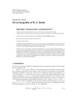
Figure 1: The unified flowgraph of fast transform algorithms: (a) flowgraph structure; (b) the basic (butterfly) operation.
can formally be an arbitrary positive integer, the efficiency
of the corresponding fast algorithm is not high for numbers
presented with a small number of prime factors. In partic-
ular, if N is a prime number, the corresponding “fast” algo-
rithm becomes, in fact, the direct matrix-vector multiplica-
tion method with the computational complexity of O(N
2
).
Here we define a class of parametric t ransforms of arbi-
trary order N such that the efficiency of the corresponding
fast algorithm does not depend on the number of factors of
N.
Definition 1. Define the class Ω of discrete orthogonal trans-
forms such that their matrices may be presented in the form
of (3), where P
( j)
, j = 1, , m +1,are(N ×N)permutation
matrices, and H
( j)
, j = 1, , m,are(N × N) block-diagonal
matrices of the form
H
( j)
=
k
s=0
V
( j,s)
⊕
I
N mod2
⊕
N/2
s=k+1
V
j,s
,(4)
where k ∈{0, 1, , N/2−1}, V
( j,s)
are (2 × 2) matrices
called spectral kernels, I
p
is either an identity matrix of order
1ifp
= 1oranemptymatrixifp = 0, the sign ⊕ stands for
the direct sum of matrices, and the sign
a for the smallest
integer larger or equal to a.
Obviously, the transform matrix presented in the for m
(3) is orthogonal if the spectral kernels in (4) are orthogonal.
It should be noted that the spectral kernels and the permuta-
tion matrices as well as the numbers m and k play the role of
parameters varying which different transforms from Ω may
be synthesized. In other words, by choosing various sets of
permutation matrices and spectral kernels, it is possible to
synthesize various orthogonal bases H
N
produced from (3).
Transforms from Ω can be computed with a fast algo-
rithm in m iterative stages:
x
0
= x; x
j
= H
( j)
·
P
( j)
x
j−1
, j = 1, , m;
y
= P
(m+1)
x
m
.
(5)
At the stage j
= 1, , m; the input vector x
j−1
to that stage
is first permuted according to P
( j)
and then the result is mul-
tiplied by the block diagonal matrix H
( j)
, which is equiva-
lent to multiplying the corresponding (2
×2) spectr al kernels
to corresponding (2
× 1) subvectors of the permuted vec-
tor. Since the matrix H
( j)
, j = 1, , m, contains at most
4
N/2≈2N nonzero entries, the complexity of the algo-
rithm (5) is estimated as O(mN) operations at the most in-
stead of O(N
2
) in the direct method. Thus, the transforms
from Ω possess fast algorithms.
The fast transform algorithm (5) may nicely be pre-
sented by the flowgraph, generically illustrated in Figure 1.
The nodes of the flowgraph (bold dotes) are divided into
m + 1 levels, the jth level representing the vector x
j
,
j
= 0, , m,from(5). There are directed edges only
between nodes of adjacent levels. Sets of edges denoted
Γ
(1)
, Γ
(2)
, , Γ
(m+1)
in Figure 1 correspond to permutation
matrices P
(1)
, P
(2)
, , P
(m+1)
so that the outputs of the Γ
( j)
block (which are marked with small circles), represent the
vector x
j
= (P
( j)
x
j−1
). Blocks V
( j,s)
, j = 1, , m, s =
0, , N
j
− 1, on Figure 1, represent executions of the ba-
sic operations, which are simple 2-point discrete orthogonal
transforms (multiplication of a 2
×2 orthogonal matrix by a
2-point vector or “butterfly”). Recall that the general form of
an orthogonal 2
× 2matrixis
V
=
uv
v
−u
,(6)
where u
2
+ v
2
= 1 and the “minus” sign may float to any of
the four entries.
Let us now consider two families of transforms within
Ω, the families of Hadamard-like and Haar-like transforms,
which are of a particular interest since they are generaliza-
tions of the classical Hadamard and Haar transforms.
Definition 2. Within the class Ω consider the family
Ω of
Hadamard-like orthogonal transforms such that all the spec-
tral kernels are orthogonal with all nonzero entries.
4 EURASIP Journal on Advances in Signal Processing
x
0
x
1
x
10
V
(1,0)
V
(1,1)
V
(1,2)
V
(1,3)
V
(1,4)
H
(1)
P
(2)
V
(2,0)
V
(2,1)
V
(2,2)
V
(2,3)
V
(2,4)
H
(2)
P
(3)
V
(3,0)
V
(3,1)
V
(3,2)
V
(3,3)
V
(3,4)
H
(3)
P
(4)
V
(4,0)
V
(4,1)
V
(4,2)
V
(4,3)
V
(4,4)
H
(4)
y
0
y
1
y
10
x
1
x
2
x
3
x
0
= xy= x
4
H
(j)
= I
1
4
s=0
V
(j,s)
, j = 1,3 H
(2)
=
4
s=0
V
(2,s)
I
1
P
(1)
= P
(5)
= I
11
H
(4)
=
2
s=0
V
(4,s)
I
1
4
s=3
V
(4,s)
P
(2)
= P
(4)
= I
1
P
sh
(10) P
(3)
= P
sh
(10)
I
1
Figure 2: The fast Hadamard-like transform of order N = 11.
The classical Hadamard transform belongs to the family
Ω of Hadamard-like transforms and corresponds to the fol-
lowing choice of the parameters: m
= log
2
N, N = 2
m
, k ≡ 0,
P
( j)
, j = 1, , m, are all the perfect shuffle permutation ma-
trices,
2
and
V
( j,s)
=
1
√
2
·
11
1
−1
,(7)
j
= 1, , m, s = 0, , N/2 − 1.Letusnotethatmulti-
plications with the coefficient 1/
√
2maybecollectedfrom
stage to stage to be pre- or post-performed before or after the
fast Hadamard transform algorithm. Therefore, only addi-
tions/subtractions will be performed during this algorithm.
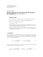
An example of a new Hadamard-like fast transform flow-
graph of order N
= 11 is shown in Figure 2.
Note that for transforms from
Ω,everymatrixH
( j)
,
j
= 1, , m, contains exactly 4N/2≈2N nonzero entries.
Therefore, the complexity of the algorithm (5)isestimated
as O(mN) for transforms from
Ω.
Definition 3. Within the class Ω consider the family Ω
of
Haar-like orthogonal transforms such that all the spectral
kernelsareorthogonaland
(1) all the entries of the spectral kernels V
( j,s)
, j =
1, , m, are nonzero for s = 0, , N
j
− 1, where
N
j
=
j times
···
N/2/2/ ···/2;
(2) V
( j,s)
= I
2
for s = N
j
, , N/2−1, j = 1, , m;
(3) P
( j)
= P
( j)
1
⊕I
N−N
j
,whereP
( j)
1
is a permutation ma-
trix of order N
j
.
2
The perfect shuffleoperatoroforder2N collects all N even components
onto the first half and the N odd components onto the second half of the
output vector.
x
0
x
1
x
10
V
(1,0)
V
(1,1)
V
(1,2)
V
(1,3)
V
(1,4)
H
(1)
P
(2)
V
(2,0)
V
(2,1)
V
(2,2)
H
(2)
P
(3)
V
(3,0)
H
(3)
V
(4,0)
H
(4)
y
0
y
1
y
10
x
1
x
2
x
3
x
0
= xy= x
4
H
(1)
= I
1
4
s=0
V
(1,s)
H
(2)
=
2
s=0
V
(2,s)
I
5
H
(3)
= I
1
V
(3,0)
I
8
H
(4)
= V
(4,0)
I
9
P
(1)
= P
(4)
= P
(5)
= I
11
P
(2)
= I
1
P
sh
(10) P
(3)
= P
sh
(6)
I
5
Figure 3: The fast Haar-like transform of order N = 11.
Haar transform is the classical representative of Ω.Itisob-
tained by taking m
= log
2
N, k ≡ 0, P
( j)
1
, j = 1, , m, is the
perfect shuffle permutation matrix of order N
j
=N/2
j
,
and V
( j,s)
= (1/
√
2)[
11
1
−1
], j = 1, , m, s = 0, , N/2
j
− 1.
Again, multiplications to the coefficient 1/
√
2maybecol-
lected from stage to stage to be pre- or post-performed.
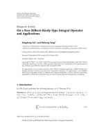
An example of a Haar-like fast transform flowgraph of
order N
= 11 is shown in Figure 3.
Note that for transforms from Ω
, the matrix H
( j)
, j =
1, , m, contains only 4N
j
≈ N/2
j−3
nonzero entries. There-
fore, the complexity of the algorithm of (5)isestimated
as O(N). Thus, the transforms from Ω
possess fast algo-
rithms, which are even faster than those for the family
Ω, for which the complexity is O(mN). This can also be
noted from the structures of the flowgraphs. While the flow-
graphs of Hadamard-like transforms all have a “semirectan-
gular” structure (equal number of nodes (butterflies) at every
stage), the flowgraphs of Haar-like transforms all have “semi-
triangular” structure (approximately twice reduced number
of nodes from a stage to the next).
2.2. Synthesis of fast Haar-like and Hadamard-like
transforms with a predefined basis functions
We now present an algorithm for synthesizing a transform
from Ω, the matrix H
N
of which has an arbitrary predefined
normalized vector h (
h=1) on its first row. Since H
N
should be orthogonal the latter condition means
H
N
h
T
= [1, 0, ,0]
T
. (8)
Therefore, the problem is reduced to defining the sets of
edges and spectral kernels in a flowgraph of the structure
shown on Figure 1 so that the first output y
0
of the flowgraph
is unity and all the others are zero provided that the vector h
was the input to the flowgraph. This may be achieved by the
following algorithm, which iteratively approximately halves
Susanna Minasyan et al. 5
the number of nonzero input components at each of the m
stages until only one nonzero component is left.
Algorithm 1 (synthesis of H
N
∈ Ω with h in the first row).
Step 1. Assume that the desired normalized vector h is the
input to a flowgraph of a fast transform that has at least
log
2
N stages, the jth stage, j = 1, , m, consisting of at
least N
j
=N/2
j
butterflies.
Step 2. For the first stage do the following.
Step 2.1. Arbitrarily define the set of edges Γ
(1)
(or equiva-
lently, arbitrarily define the permutation matrix P
(1)
).
Step 2.2. Define spectral kernels
V
(1,s)
=
1
u
1,s
2
+
v
1,s
2
u
1,s
v
1,s
v
1,s
−u
1,s
, s = 0, , N
1
− 1
(9)
by assigning to the pair [u
1,s
, v
1,s
] the values of the corre-
sponding two components of the vector h that are input to
the sth operation of the first stage of the flowgraph. If, how-
ever, both of these components are equal to zero, then arbi-
trar ily define the corresponding spectral kernel. If only one
of these components is nonzero, then define the correspond-
ing spec tral kernel to be an identity matrix of size 2
×2. Note
that this definition of spectral kernels implies that the second
outputs of all butterflies are always zeros.
Step 2.3. Apply the first stage of the flowgraph to the input
vector h and obtain vector x
1
.
Step 3. For every stage j
= 2, , m do the following.
Step 3.1. Define the set of edges Γ
( j)
so that it passes the first
(nonzero) outputs of butterflies of the previous stage to the
inputs of uppermost butterflies of the current stage. Note
that al l the
N/2
j
nonzero outputs of the previous stage will
be distributed among N
j
=N/2
j
butterflies of the previous
stage.
Step 3.2. Define the spectral kernels
V
( j,s)
=
1
u
j,s
2
+
v
j,s
2
u
j,s
v
j,s
v
1,s
−u
j,s
, (10)
where [u
j,s
, v
j,s
] are the corresponding two components of
the vector x
j−1
that are passed to the sth operation of the
current stage of the flowgraph. Again if both of these com-
ponents are equal to zero, then arbitrarily define the corre-
sponding orthogonal kernel, and if only one of these com-
ponents is nonzero, then define the corresponding spectral
kernel to be an identity 2
× 2matrix.
Step 3.3. Apply the jth stage of the flowgraph to the vector
x
j−1
, and obtain vector x
j
.
Step 4. Arbitrarily define the set of edges Γ
m+1
butsothatit
does not change the position of the first component.
Since the number of nonzero components approximately
halves from stage to stage and since the number of stages is
m
≥ log
2
N, only the first output of the flowgraph will be
nonzero and equal to unity (the input h was normalized).
Thus, the corresponding transform: (a) will have an orthog-
onal matrix (spectral kernels were selected orthogonal); (b)
may be computed with a fast algorithm; (c) will contain the
desired predefined vector h in its first row.
Let us consider an example of synthesizing a Haar-like
transform of order N
= 8 with the generating vector h =
(1/
√
204) · [1,2,3,4,5,6,7,8] asitsfirstrow.The matrixH
8
of the desired transform can be presented as
H
8
= P
(4)
H
(3)
P
(3)
H
(2)
P
(2)
H
(1)
P
(1)
, (11)
wherewedefineP
(1)
= P
(4)
= I
8
. Then, according to Step 2.2
of Algorithm 1 we define
H
(1)
=
1
√
5
12
2
−1
⊕
1
5
34
4
−3
⊕
1
√
61
56
6
−5
⊕
1
√
113
78
8
−7
.
(12)
With this matrix we obtain the result of the first stage:
x
1
= H
(1)
h =
1
√
204
√
5, 0, 5,0,
√
61, 0,
√
113, 0
T
.
(13)
We then define the permutation matrix P
(2)
= P
sh
(8) to be
the perfect shuffle of order 8. Applying P
(2)
to x
1
results in
P
(2)
x
1
=
1
√
204
·
√
5, 5,
√
61,
√
113,0,0,0,0
T
.
(14)
Now, according to Step 3.2,wedefineH
(2)
as
H
(2)
=
1
√
30
√
55
5
−
√
5
⊕
1
√
174
√
61
√
113
√
113 −
√
61
⊕
I
4
.
(15)
Applying this matrix to P
(2)
x
1
yields
x
2
= H
(2)
P
(2)
x
1
=
1
√
204
·
√
30, 0,
√
174,0,0,0,0
T
.
(16)
Taking P
(3)
= P
(sh)
(4) ⊕ I
4
and defining
H
(3)
=
1
√
204
√
30
√
174
√
174 −
√
30
⊕
I
6
, (17)
we will find
x
3
= H
(3)
P
(3)
x
2
= [1,0,0,0,0,0,0,0]
T
. (18)
6 EURASIP Journal on Advances in Signal Processing
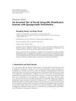
Afixed
transform
Quantization
and hard
threshold
Lossless
coding
Channel/
storage
Lossless
decoding
Dequantization
Inverse
transform
Figure 4: Generic transform-based image compression/decom-
pression system.
Substituting the defined matrices into the factorization
(11)ofH
8
we obtain the desired transform matrix
H
8
≈
1
√
204
·
⎡
⎢
⎢
⎢
⎢
⎢
⎢
⎢
⎢
⎢
⎢
⎢
⎢
⎣
12345678
2.44.87.29.6
−2.1 −2.5 −2.9 −3.3
5.811.7
−3.5 −4.70 0 0 0
00007.48.8
−5.6 −6.4
12.8
−6.4000000
0011.4
−8.60 0 0 0
000010.9
−9.10 0
00000010.7
−9.4
⎤
⎥
⎥
⎥
⎥
⎥
⎥
⎥
⎥
⎥
⎥
⎥
⎥
⎦
.
(19)
Note that the obtained matrix has a structure similar to
that of classical Haar transform matrix in the sense of dis-
tribution of positive, neg a tive, and zero entries. At the same
time it has the desired generating vector as its first row.
2.3. Fast Haar-slant and Hadamard-slant transforms
In this section, we further develop Algorithm 1 and con-
struct orthogonal N
× N matrices (arbitrary N) having
the representations (3), (4) and involving more than one
given orthogonal vectors as rows. In particular, one can
consider the case of slant-like transforms wherein the first
row of the matrix is the normalized constant vector e
=
(1/
√
N) · [1, 1, ,1] of length N, and the second row is
a normalized slant (monotonically decreasing) vector a
=
[α
0
, α
1
, , α
N−1
] of arbitrary slanting angle γ = tan
−1
(α
i+1
−
α
i
), i = 0, , N −2 and orthogonal to the first row. The ma-
trix H
N
of the desired Haar-slant (or Hadamard-slant) trans-
form may be found as the product
H
N
=
I
1
⊕ H
N−1
H
N
, (20)
where H
N
∈ Ω (or H
N
∈ Ω) is a matrix having e at its first
row , and H
N−1
∈ Ω (or H
N−1
∈ Ω)isan(N −1) × (N − 1)
matrix having the last N
−1 components of the vector H
N
a
T
atitsfirstrow.BothmatricesH
N
and H
N
may be obtained
by Algorithm 1 with corresponding input vectors. Similarly
more than two predefined vectors, orthogonal to each other,
may be involved into the transform matrix.
3. IMAGE COMPRESSION ALGORITHMS
A traditional block transform-based image compression
scheme (see Figure 4) applies a fixed transform to every
subimage (8
× 8 block) and implements the actual compres-
sion in the transform domain by quantizing the transform
coefficients followed by lossless encoding of the quantized
values. Obtained bitstream is sent to the decoder, which im-
plements inverse procedures to obtain an estimate of the en-
coded image. This scheme is motivated by the fact that, for
most of natural images, content within small blocks is rather
flat meaning high correlation between image pixels. When
a proper transform (typically 2D separable DCT) is applied
to such a flat block the largest portion of energy tends to be
concentrated within relatively small number of transform co-
efficients. The better the transform concentrates the energy,
the better is the performance of the compression scheme
meaning closeness of the estimate on the decoder output to
the original image on the encoder input at given compres-
sion ratio (ratio between the number of bits representing
the original i mage and the number of bits representing the
compressed image). The known fixed transforms, including
DCT, perform rather well for flat image blocks but typically
fail for act ive blocks with low correlation between pixels. The
performance of the block-based image compression scheme
could potentially be improved by possibility to use several
transforms each specifically synthesized for a certain type of
blocks. Parametric transforms of Section 2 and the method
of synthesizing them may offer such an opportunity.
Based on (8), it is clear that parametric transforms are
able to concentrate arbitrary image block energy into just
one transform coefficient, which would be the ideal energy
concentration. For this, however, a transform should be syn-
thesized per each column and per each row of an image
block used as generating vectors of these transforms. Apply-
ing these transforms to the image block so that each of them
is applied to its generating vector would result into a matrix
with only nonzero entry at the up-left corner. However, there
is also maximally large overhead in such an approach since all
the generating vectors, that is whole the original input image
block, should also be sent to the decoder.
Theoverheadmayandshouldbereducedbycompro-
mising the energy concentration property. There are differ-
ent opportunities for such a tradeoff.Inaprioriresearch
we have compared several approaches with extensive simula-
tions. Currently the following approaches described in Algo-
rithms 2 and 3 were considered being suitable ones. In both
approaches, parametric transforms are synthesized accord-
ing to generating vectors that are obtained as averages of dif-
ferently formed image subvectors (block rows and columns).
The basic (experimentally confirmed) assumption here is
that average of several vectors (say x
i
, i = 1, , n) having
similar properties tends to preserve shapes of these vectors.
Therefore, the parametric transform synthesized according
to the generating vector being an average of several vectors,
say x
i
, i = 1, , n, would still efficiently concentrate energy
of each of the vectors x
i
, i = 1, , n. In order to classify
image subvectors (block rows and columns) the efficiency of
DCT-based compression could be used.
Below, two image compression schemes are proposed
[24, 25]. In both schemes, the fixed classical DCT is used in
combination with different parametric Haar-like transforms,
Susanna Minasyan et al. 7
Input
image
8 × 8subimages
Transfo r m 0
(DCT)
Parametric
transform 1
Parametric
transform 2
Parametric
transform k
Generating
vectors
Adaptive
transforms that
are synthesized
until
improvement
may be
achieved in the
compression
quality
Selection
(for every subimage
the transformed
block with the best
compression quality
is selected)
Quantization and/or thresholding
Form a matrix
CLASS, indicating
the numbers of
selected transforms
for every subimage
Lossless encoding
Bitstream
Figure 5: Image coder of proposed compression algorithm.
each synthesized and adapted to a certain type of blocks. The
proposed compression schemes have performance that can-
not be worse than a DCT-based scheme.
3.1. Iterative image compression scheme (IICS)
The first proposed scheme is iterative one where the classical
DCT is used at the first iteration and iteratively synthesized
Haar-like transforms are used at the following iterations. The
main idea of the algorithm is to apply few parametric Haar-
like transforms, each specifically designed for a specific class
of blocks. Transforms are iteratively synthesized based on the
blocks for which lowest compression efficiency was achieved
with the previous transform (DCT being the initial one). The
iterative process is continued as long as a worth-while over-
all compression efficiency improvement is observed for the
whole image. The diagr am of the image coder is depicted
by Figure 5. A more detailed, step-by-step description of the
proposed scheme follows.
Algorithm 2 (IICS).
Step 1. Apply the traditional image compression scheme as
shown in Figure 4. In our current implementation, the in-
put N
× M image is partitioned into 8 × 8 blocks, which are
DCT transformed, uniformly quantized, and hard thresh-
olded. Then, zig-zag scanning followed by lossless encoding
is applied to form the output bitstream.
Step 2. Initialize an n
×m matrix CLASS (n = N/8, M = m/8)
with all the zero entries. The matrix CLASS will iteratively
be updated to contain the indices of transforms assigned to
the blocks. The DCT is indexed by zero and the transforms
synthesized at the following iterations are indexed by the
numbers of corresponding iterations.
Step 3. Measure the compression efficiency for every block
and collect blocks with worst compression efficiency values.
To measure the compression efficiency for a block B we used
the following functional:
CE(B)
=
1
c
1
· SE(B)+c
2
· NB(B)
, (21)
where c1, c2 are parameters that control the relative signifi-
cance between the compression ratio and the distortion; NB
is the number of bits representing the block after coding
(DCT, quantization and lossless encoding); SE is the absolute
difference between the original and the reconstructed image
block. Higher CE value indicates better compression. The re-
lation between parameters c1andc2 is such that
c
1
=
c
max
all B
SE
DCT
(B)
, c
2
=
1 − c
max
all B
NB
DCT
(B)
,
(22)
where 0 <c<1, SE
DCT
(B)andNB
DCT
(B) are corresponding
characteristics obtained by DCT coding the block B.Note
that larger value of c means more significance of achieving
less distortion rather than achieving higher compression.
To collect blocks with the worst coding efficiency we use
the condition
CE(B) <α
· mean
all B
CE(B)
, (23)
where α is a parameter. Blocks satisfying this condition were
collected.
Step 4. Synthesize a new 2D parametric transform adapted
for the blocks collected at Step 3. In current implementation,
a separable 2D transform is synthesized such that each block
is multiplied by a matrix H
(1)
from the left-hand side, and
by another matrix H
(2)
from the right-hand side. The para-
metric transform H
(1)
is generated by the transposed mean
column and the transform H
(2)
is generated by the mean row
of the collected worst blocks.
Step 5. Apply the new synthesized transform to every block
of the image. For every block, if the current transform gives
asmallervalueofCE(B) than the previous transform, assign
the current transform to the given block. Update the matrix
CLASS correspondingly. Note that in calculation of CE(B)
the overhead bits for presenting the generating vectors and
the CLASS matrix must be taken into account.
Step 6. Lossless encode the generating vectors and the CLASS
matrix. Compare the compression efficiency for the whole
image (taking into account the overhead) to the compression
efficiency obtained at previous iteration. If there is enough
improvement, then go to Step 3. Otherwise, send the re-
sults of the previous iteration (the compressed blocks, loss-
less coded generating vectors-and lossless-coded CLASS ma-
trix) to the storage or channel.
8 EURASIP Journal on Advances in Signal Processing
Bitstream
Lossless
decoder
and IQ
Optimally
decoded
blocks
Generating
vectors
Matix
CLASS
Block
distribution
to transforms
according to
matrix
0
1
k
IDCT
IPT 1
.
.
.
IPT k
Synthesis of inverse
parametric transforms
Rec.
image
Figure 6: General scheme of an image decoder for two proposed
compression algorithms.
Decoder performs the reconstruction of the blocks ac-
cording to the matrix CLASS, elements of which show to de-
coder the number of the received generating vector based on
which decoder constr ucts inverse transform and implements
the reconstruction of the image. The decoder of the proposed
scheme is illustrated in Figure 6.
3.2. Multiple transform-based image compression
(MTIC) algorithm
The idea of the second proposed scheme is to apply multi-
ple transforms to each image block and to select the best one
according to a quality functional. Multiple transform-based
image coder diagram is shown in Figure 7. The decoder in
this algorithm performs the same procedure as in the pre-
vious scheme (see Figure 6). A more detailed, step-by-step
description of the proposed scheme follows.
Algorithm 3 (MTIC).
Step 1. At this step a JPEG-like or DCT-based image com-
pression scheme is applied to the given N
× M image.
Step 2. For each nonoverlapping 8
× 8imageblockB of the
input image the quality functional CE(B) according to (21)is
calculated. The values of the quality functional for all blocks
are collected in a CEM matrix of order (N/8)
×(M/8) which
is then scaled to contain entries between zero and one. Thus,
the matrix QM contains coding efficiency information ob-
tained after the DCT-based compression of the original im-
age.
Step 3. This is the block classification stage. At first, the range
[min, max] is determined, where min and max indicate the
minimal and maximal values of the QM matrix, respectively.
Then, a series of subdivisions is applied to the range such that
at each time the left half of previous division is selected for
the following subdivision. Currently we a pply only three sub-
divisions since the more the number of subranges, the more
overhead and the complexity of the algorithm. Blocks corre-
sponding to one subrange are collected together. Therefore,
after classification we will have four types of blocks corre-
sponding to four sequential subranges. Note that, on the av-
erage, smoother image blocks will fall into the subranges on
the right side of the original range and less smooth blocks to
the left subranges.
Step 4. Three new parametric 2D transforms are synthesized
based on blocks collected to the lefter subranges. For every
separable parametric 2D transform H(i), i
= 1, 2, 3, a matrix
H
(1)
i
, that is multiplied to a block from the left-hand side and
another matrix H
(2)
i
that is multiplied from the right-hand
side are synthesized. The parametric transform H
(1)
i
is gener-
ated by the transposed mean column and the transform H
(2)
i
is generated by the mean row of the collected blocks within
ith subrange. Therefore, three parametric 2D transforms are
synthesized which correspond to three subranges.
Step 5. Initialize n
× m matrix CLASS (n = N/8, m = M/8)
that will contain the indices of transforms assigned to the
blocks. DCT is indexed by zero and the three newly synthe-
sized transforms are indexed from 1 to 3.
Step 6. Every 8
× 8 block is processed by four transforms,
that is, 2D DCT and the three new synthesized parametr ic 2D
transforms, are applied to every image block. Then, all trans-
formed blocks are quantized, hard thresholded, and entropy
encoded. Here the best transform out of four is selected for
each block according to the quality functional CE (see (21)).
Step 7. Image blocks which are compressed with the “best”
selected transforms are collected in a separate matrix. Since
there is an overhead due to u sing parametric transforms, the
question of “benefit” and “cost” of the parametric transforms
becomes crucial. To solve this problem we need to verify the
following condition: if the total “benefit” from using certain
parametric transform over all blocks where it was selected
is less than the cost of using that transform, it is not used.
Every block where this tr a nsform was selected as the “best”
is replaced with the DCT processed block. Otherwise, if the
“benefit” is more than the cost, the corresponding transform
is used.
Step 8. Update the block classification matrix CLASS corre-
spondingly.
Step 9. The optimally coded blocks, the lossless-coded gener-
ating vectors, and the lossless-coded CLASS matrix represent
the information, which is sent to the storage or channel.
Note that the DCT transform was indexed by 0 and the
parametric transforms synthesized at Step 5 were indexed by
the numbers from 1 to 3. Therefore, the elements of CLASS
matrix were 0, 1, 2, 3. One can see that the larger number
of fragmentations was used in synthesizing Haar-like trans-
forms, the larger number of bits is needed to represent the
CLASS matrix resulting in a larger overhead. However, at
Step 7 transforms whose benefit could not cover this over-
head were removed and the CLASS matrix was accordingly
Susanna Minasyan et al. 9
Input image
Image block classification according to compression quality q
of DCT coding
Class 0
blocks with
best CE
Class 1
blocks with
2nd best CE
Class 2
blocks with
3rd best CE
Class 3
blocks with
worst CE
Generating
vector pair
1
Generating
vector pair
2
Generating
vector pair
3
DCT
Synthesize
parametric
transform
1
Synthesize
parametric
transform
2
Synthesize
parametric
transform
3
Input image
blocks
Spectrum 0 Spectrum 1 Spectrum 2 Spectrum 3
Form the matrix
CLASS containing
indices of best
transforms for all
blocks
Correcting the
matrix CLASS
Generating vectors
of remained tr-s
Post analysis of benefits and costs of every synthesized transform.
Remove transforms with cost exceeding the benefit.
Reassign blocks corresponding to removed transforms to DCT
Best spectrum selection according to compression qualities.
Collecting best spectra for all image blocks
Lossless encoding
Output bitstream
Figure 7: Multiple transform-based image coder.
updated at Step 8. Therefore, the overhead’s influence to the
overall coding quality can never be larger than the improve-
ment due to using the final set of parametric transforms,
that is, the performance of the proposed algorithm cannot
be worse than that of the pure DCT-based algorithm.
4. SIMULATIONS
Both parametric transform-based image compression
schemes were experimented on different test images and
compared to the similar image compression scheme based
on fixed DCT.
Some results obtained by the iterative compression
scheme (Algorithm 2)arepresentedinTable 1. In this ta-
ble, the results of the first iteration (presented in first rows
for each image) correspond to the DCT-based compression
scheme. Next iterations correspond to the case where para-
metric Haar-like transforms are also used. The last column in
Tab le 1 presents parameters used in the experiments where
c is the constant used in compression efficiency functional
calculation (see (21), (22)), α is the constant used to check
“compressability” of the given block according to (23), and
Q is the quantization step that controls the bitrate in com-
Table 1: Simulation results of Algorithm 2 (IICS).
Image Iterat.
Comp.
ratio
PSNR Parameters
Cameraman
1 6.29 38.17 c = 0.05
2 6.30 38.52 α = 1
3 6.28 38.54 Q = 12.8
Medicalim
1 4.35 45.78 c = 0.9
2 4.39 46.14 α = 0.8
3 4.35 46.19 Q = 4
Kidney
1 20.15 41.67 c = 0.6
2 20.74 42.05 α = 1.2
3 20.28 42.09 Q = 12
Oesoph
1 20.93 42.87 c = 0.8
2 24.09 43.60 α = 0.9
3 24.09 43.60 Q = 13.6
pressed images. Steps 1 to 6 of the proposed algorithm are it-
erated while the compression efficiency is increased by a pre-
defined value of 0.2 at least. Iteration process is terminated
when there is no enough increase in compression efficiency at
10 EURASIP Journal on Advances in Signal Processing
Table 2: Simulation results of Algorithm 3 (MTIC).
Image Tran sf o rm
Comp.
ratio
PSNR Parameters
Compound
DCT
8.3
38.86
c = 0.67, Q = 20
q1
= 12
q2
= 10
q3
= 8
Proposed 44.43
Lena
DCT
8.7
34.73
c = 0.58, Q = 19.2
q1
= 24.96
q2
= 23.04
q3
= 7.68
Proposed 35.58
Cameraman
DCT
7.3
36.66
c = 0.37, Q = 16
q1
= 16
q2
= 14.4
q3
= 12.8
Proposed 38.34
Mandril
DCT
8.4
28.38
c = 0.1, Q = 36
q1
= 43.2
q2
= 39.6
q3
= 36
Proposed 28.41
current iteration. Therefore, the final (the best) result of the
proposed algorithm corresponds to the result of the penul-
timate iteration (highlighted with bold font type). One can
see from Ta ble 1 that, for approximately the same compres-
sion ratios, PSNR is increased up to penultimate iteration for
all the images.
To analyze the performance of Algorithm 2,PSNRver-
sus bitrate (bpp) plots were also obtained for several im-
ages. In these experiments, the values of parameters c and
α were fixed for ever y image and the parameter Q was varied
to achieve different bitrates. Figure 8 shows plots for several
images. One can see that essential performance is achieved
especially for the image “Compound.”
Tab le 2 presents some results of experiments for
Algorithm 3 in comparison with the DCT-based scheme. The
last column indicates the parameter values used in the cor-
responding experiments. Here c is the same as in Table 1
(see (21), (22)), Q is the quantization step used in DCT-
based coding (both at the first step of Algorithm 3 and in
the reference DCT-based scheme), and q1, q2, q3arequan-
tization steps used in association with corresponding three
parametric t ransforms synthesized according to Algorithm 3.
Tab le 2 illustrates the essential performance improvement
for all the test images. Figure 9 shows PSNR versus bitrate
plots of Algorithm 3 for different images.
To visualize the performance of the parametric-trans-
form-based image compression schemes, Figure 10 illus-
trates comparative performance of Algorithms 2 and 3 with
that of the DCT-based scheme for the medical image “kid-
ney” (as known in [15], visual quality is the most important
characteristic of medical image compression schemes).
It should also be noted that both Algorithms 2 and 3
do not only perform image compression but also implement
block classification. Such classification is an important prop-
40
42
44
46
48
50
52
PSNR
0.20.40.60.81 1.21.41.61.82
bpp
DCT based
Algorithm 2
(a) Kidney image: Algorithm 2 versus DCT-based compression
32
34
36
38
40
42
44
46
48
PSNR
0.50.60.70.80.911.11.21.31.41.5
bpp
DCT based
Algorithm 2
(b) Compound image: Algorithm 2 versus DCT-based compression
Figure 8: PSNR versus bitrate plots for images: (a) “Kidney” (c =
0.9, α = 1); (b) “Compound” (c = 0.5, α = 1).
erty, especially for images composed of subimages of several
types. Figure 11 presents plots of the matrices CLASS ob-
tained by Algorithms 2 and 3 for the Compound image. The
black pixels in this plot correspond to the use of DCT, while
white pixels correspond to the use of parametric Haar-like
transforms.
As can be seen from Figure 11, DCT is associated with flat
regions of the image, while new transforms perform around
nonflat regions, which is the expected result.
Susanna Minasyan et al. 11
26
28
30
32
34
36
38
40
42
44
46
PSNR
0.20.40.60.811.21.41.61.82 2.2
bpp
DCT based
Algorithm 3
(a) Cameraman image: Algorithm 3 versus DCT-based com-
pression
26
28
30
32
34
36
38
40
42
44
PSNR
00.511.522.5
bpp
DCT based
Algorithm 3
(b) Lena image: Algorithm 3 versus DCT-based compression
40
42
44
46
48
50
52
54
PSNR
0.20.40.60.811.21.41.61.82
bpp
DCT based
Algorithm 3
(c) Kidney image: Algorithm 3 versus DCT compression
Figure 9: PSNR versus bitrate plots for images: (a) “Cameraman;”
(b) “Lena;” (c) “Compound.” For all images c
= 0.5, Q = 8 ···80,
q1
= Q, q2 = 0.9Q, q3 = 08Q.
(a) (b)
(c) (d)
Figure 10: Medical image “Kidney”: (a) the original image; (b)
6.53 times DCT compressed image; ( c) 6.67 times compressed
image with Algorithm 2; (d) 6.72 times compressed image with
Algorithm 3.
(a)
(b) (c)
Figure 11: Results for “Compound” image: (a) original image; (b)
matrix CLASS obtained by Algorithm 2; (c) matrix CLASS obtained
by Algorithm 3.
5. UNIFIED ARCHITECTURE FOR SYNTHESIS AND
IMPLEMENTATION OF PARAMETRIC TRANSFORMS
Many different architectures for fixed transforms and few ar-
chitectures for families of transforms have been proposed in
12 EURASIP Journal on Advances in Signal Processing
MUX
MUX
u
v
x
x
c
1
c
2
c
1
c
2
c
1
c
1
TG
TG
+/
−
X
−1/2
Shift
registers
Shift
registers
Figure 12: The structure of the generic PE for unified architectures
for parametric transform synthesis and implementation.
the literature. However, to the best of our knowledge, no uni-
fied architecture that may synthesize a transform according
to a set of parameters and then implement the synthesized
transform is know n. In this section, we propose architectures
that operate in two modes: synthesis mode and implemen-
tation mode. In the synthesis mode, the architecture has a
desired vector h in its input and computes the parameters
(spectral kernels) that correspond to an orthogonal trans-
form of a given type (Haar-like, Hadamard-like, etc.). These
parameters are stored in registers and then are used in the im-
plementation mode where the synthesized transform is ap-
plied to an arbitrary input vector.
Most of the architectures for fixed transforms or trans-
form families are designed by mapping the flowgraph of the
corresponding fast transform algorithm into architectures of
one or another type (pipelined, iterative, parallel pipelined,
folded, etc.). Vertical projections of the flowgraph to chains
of processing elements (PEs) that implement the “butter-
flies” lead to pipelined designs. In pipelined designs, stages
of the flowgraph are performed in parallel while the butter-
flies of a stage are performed sequentially. Typically, shift reg-
isters, delays, and multiplexers are used to implement per-
mutations according to the sets of edges of the correspond-
ing flowgraph. Horizontal projections to arrays of PEs lead
to iterative processors. Permutations according to the sets of
edges are implemented within the interconnection network
between PEs. Actually, the flowgraph itself where the blocks
corresponding to spectral kernels are replaced by PEs may, in
principle, be considered as a parallel-pipelined (or stream)
architecture. To reduce the size of the architectures, usually
folding is applied where the number of PEs is used, so that
each PE implements a number of “butterflies.”
Here, we will not go into deeper architectural details but
will concentrate on a generic PE structure that, when used
in any architecture for a fast transform algorithm involving
“butterflies,” allows synthesizing new transforms based on
Algorithm 1 and at the same time efficiently implements the
“butterflies.” The generic PE structure is shown on Figure 12.
It operates in two modes. In synthesis mode, the control
signal c
1
c
2
to multiplexers is first set to c
1
c
2
= 00 so that its
every input is multiplied to itself. The results of multiplica-
tions (squarings) are added within the adder and the sum is
then inverted within the “Inv (1/x)” block. Then the control
signal to the multiplexers is set to c
1
c
2
= 01 so that the result
(1/(u
2
+ v
2
)) is sent to the two multipliers which obtain the
two desired parameters u/(u
2
+ v
2
)andv/(u
2
+ v
2
) w hich are
stored in the shift register file (at this point the transmitter
gate “TG” is open). In the shift register file there are as many
registers as many “butterflies” the PE will be implementing
in the implementation mode. When parameters for all but-
terflies assigned to the given PE are computed, the control
signal is set to c
1
c
2
= 10 which switches PE to the implemen-
tation mode. The parameters from shift registers are sent to
multipliers so that the first row of the spectral kernel is mul-
tiplied to the input vector. At the next step the control signal
is set to c
1
c
2
= 11 so that the second row of the spectral ker-
nel is multiplied with the input pair. The results are sent to
the next, within the given architecture, PE for computing the
parameters of butterflies that correspond to that PE.
Note that the square root divider block within the PE is
the most complicated block. Its complexity is approximately
the same as of the divider (see, e.g., [26]). However, this block
is out of the critical path in the implementation mode so that
the speed of the proposed PE in this mode is a pproximately
the same as if it was designed only to implement a fixed trans-
form. It is much slower in the synthesis mode. In most of
the applications synthesizing is applied much less frequently
compared to the implementation of the transforms (see Al-
gorithms 2 and 3). One way to exclude the square root di-
vider block from the PE could be creating a look-up table
(LUT) outside of the PE and reuse this LUT for every PE
within the architecture for transforms. Efficiency of this ap-
proach depends on the working precision of the architec-
ture and the size of the transforms being implemented. An-
other way to exclude this complex block could be based on
computing the parameters of the transform outside of the
hardware architecture for the transform and then “manually”
tuning the PE to the desired transform by directly loading
computed parameters to the shift registers. However, the al-
ternative presented on Figure 12 allows also automatic gen-
eration of transform parameters meaning that the transform
may automatically be adapted to the input signal or image.
6. CONCLUSION
A new class of parametric transforms was investigated in two
new image compression schemes. Experimental results illus-
trated a moderate performance improvement for natural im-
ages and significant performance improvement for images
of certain types such as medical images and complex im-
ages consisting of fragments of essentially different types. A
methodology for developing VLSI architectures for synthe-
sizing and implementation of the parametric transforms was
also proposed.
Susanna Minasyan et al. 13
REFERENCES
[1] W. B. Pennebaker and J. L. Mitchell, JPEG Still Image Data
Compression Standard, Van Nostrand Reinhold, New York, NY,
USA, 1993.
[2] S. S. Agaian, “Optimal algorithms of fast orthogonal trans-
forms and their implementation on computers,” in Kiber-
netika I Vichislitelnaya Tekhnika, issue 2, pp. 231–319, Nauka,
Moscow, Russia, 1986.
[3] S. S. Agaian, J. Astola, and K. Egiazarian, Binary Polynomial
Transforms and Non-linear Digital Filters, Marcel Dekker, New
York, NY, USA, 1995.
[4] S. S. Agaian and A. K. Matevosian, “Generalized Haar trans-
forms and automation systems for testing quality of circuits,”
Acta Cybernetica, vol. 5, pp. 345–362, 1981.
[5] N.U.AhmedandK.R.Rao,Orthogonal Transforms for Digital
Signal Processing, Springer, Secaucus, NJ, USA, 1975.
[6]O.K.Ersoy,“Acomparativereviewofrealandcomplex
Fourier-related transforms,” Proceedings of the IEEE, vol. 82,
no. 3, pp. 429–447, 1994.
[7] A. K. Jain, Fundamentals of Digital Image Processing, Prentice-
Hall, Englewood Cliffs, NJ, USA, 1989.
[8] A. D. Poularikas, Ed., The Transforms and Applications Hand-
book, CRC Press, Boca Raton, Fla, USA, 1996.
[9] H. S. Malvar, Signal Processing with Lapped Transforms,Artech
House, Norwood, Mass, USA, 1992.
[10] M. V. Wickerhauser, Adapted Wavelet Analysis from Theory to
Software, IEEE Press, A. K. Peters, Wellesley, Mass, USA, 1994.
[11] V. G. Labunets, “A unified approach to fast transfor-
mation algorithms,” in Primeneniye Ortogonalnix Metodov
pri Obrabotke Signalov i Analize System, pp. 4–14, UPI,
Sverdlovsk, Russia, 1980.
[12] M. Traxtman and V. A. Traxtman, Osnovi Teorii Discretnix
Signalov na Konechnix Intervalax,SovetskoyeRadio,Moscow,
Russia, 1975.
[13] L. P. Yaroslavskiy, “Some questions of the theory of discrete
orthogonal transforms of signals,” in Cifrovaya Obrabotka Sig-
nalov I ee Primeneniya, pp. 33–71, Nauka, Moscow, Russia,
1981.
[14] C. Christopoulos, A. Skodras, and T. Ebrahimi, “The JPEG
2000 still image coding system: an overview,” IEEE Transac-
tions on Consumer Electronics, vol. 46, no. 4, pp. 1103–1127,
2000.
[15] D. H. Foos, E. Muka, R. M. Slone, et al., “JPEG 2000 compres-
sion of medical imagery,” in Medical Imaging 2000: PACS De-
sign and Evaluation: Engineering and Clinical Issues, vol. 3980
of Proceedings of SPIE, pp. 85–96, San Diego, Calif, USA,
February 2000.
[16] N. Ponomarenko, V. Lukin, K. Egiazarian, and J. Astola, “DCT
based high quality image compression,” in Proceedings of the
14th Scandinavian Conference on Image Analysis (SCIA ’05),
pp. 1177–1185, Joensuu, Finland, June 2005.
[17] A. I. Solodovnikov, I. I. Kanatov, and A. M. Spivakovskii, “Syn-
thesis of orthogonal bases from a generalized spectral kernel,”
in Voprosy Teorii Sistem Avtomaticheskogo Upravleniya, vol. 2,
pp. 99–112, LGU, Leningrad, Russia, 1978.
[18] A. I. Solodovnikov, “Synthesis of complete orthonormal sys-
tems of functions having fast transform algorithm,” in Vo -
prosy Teorii System Avtomaticheskogo Upravleniya, vol. 4, pp.
94–105, LGU, Leningrad, Russia, 1978.
[19] H. C. Andrews and K. L. Caspary, “A generalized technique
for spectral analysis,” IEEE Transactions on Computers, vol. 19,
no. 1, pp. 16–25, 1970.
[20] S. S. Agaian and D. Z. Gevorkian, “Complexity and parallel
algorithms of discrete orthogonal transforms,” in Kibernetika I
Vichislitelnaya Tekhnika, issue 4, pp. 124–169, Nauka, Moscow,
Russia, 1988.
[21] S. S. Agaian and D. Gevorkian, “Synthesis of a class of orthogo-
nal transforms: parallel SIMD-algorithms and specialized pro-
cessors,” Pattern Recognition and Image Analysis,vol.2,no.4,
pp. 394–408, 1992.
[22] S. Minasyan, D. Guevorkian, and H. Sarukhanyan, “On pa-
rameterized fast Haar- and Hadamard-like transforms of arbi-
trary order,” in Proceedings of the 3rd International Conference
on Computer Science and Information Technologies (CSIT ’01),
pp. 294–298, Yerevan, Armenia, September 2001.
[23] S. Minasyan, D. Guevorkian, S. S. Agaian, and H.
Sarukhanyan, “On “slant-like” fast orthogonal trans-
forms of arbitrary order,” in Proceedings of the 4th EURASIP
IEEE Region and International Symposium on Video/Image
Processing and Multimedia Communications (VIPromCom
’02), pp. 309–314, Zadar, Croatia, June 2002.
[24] S. Minasyan, J. Astola, and D. Guevorkian, “An image com-
pression scheme based on parametric Haar-like transform,” in
Proceedings of IEEE International Symposium on Circuits and
Systems (ISCAS ’05), vol. 3, pp. 2088–2091, Kobe, Japan, May
2005.
[25] J. Astola, S. Minasyan, and D. Guevorkian, “Multiple trans-
form based image compression technique,” in Pro ceedings
of the 5th IASTED International Conference on Visualization,
Imaging, and Image Processing, Benidorm, Spain, September
2005.
[26] P. Soderquist and M. Leeser, “Division and square root: choos-
ing the right implementation,” IEEE Micro, vol. 17, no. 4, pp.
56–66, 1997.
Susanna Minasyan graduated from Yerevan
State Engineering University of Armenia
(SEUA) where in 1996 she got her Diploma
with honors in the field of automated sys-
tems of information processing and man-
agement and in 1998 she received her M.S.
degree in mathematics. From 1998 to 2001
she worked as a lecturer at the Department
of Mathematics, SEUA. From 2001 to 2004,
she was with Institute for Informatics and
Automation Problems, National Academy of Sciences of Arme-
nia. In 2004, she moved to Tampere University of Technology
(TUT), Finland, first as a Visiting Researcher at Tampere Interna-
tional Center of Sign al Processing and then as a Ph.D. student and
researcher. Her research areas include adaptive transform-based
methods in signal and image processing, and spectr al techniques.
Jaakko Astola received his Ph.D. degree in
mathematics from Turku University, Fin-
land, in 1978. From 1976 to 1977 he was
with the Research Institute for Mathemat-
ical Sciences of Kyoto University, Kyoto,
Japan. Between 1979 and 1987 he was with
theDepartmentofInformationTechnol-
ogy, Lappeenranta University of Technol-
ogy, Lappeenranta, Finland. In 1984 he
worked as a Visiting Scientist in Eindhoven
University of Technology, The Netherlands. From 1987 to 1992 he
was Associate Professor in applied mathematics at Tampere Univer-
sity, Tampere, Finland. From 1993 he has been Professor of signal
14 EURASIP Journal on Advances in Signal Processing
processing at Tampere University of Technology and is currently
Head of Academy of Finland Centre of Excellence in Signal Pro-
cessing leading a group of about 80 scientists. His research interests
include signal processing, coding theory, spectral techniques, and
statistics.
David Guevorkian received his M.S. de-
gree (with honors) in applied mathemat-
ics from Yerevan State University, Arme-
nia, in 1983, his Ph.D. degree in cybernetics
and computational mathematics from Kiev
State University, Ukraine, in 1987, and his
Dr. Tech. degree in signal and image pro-
cessing from Tampere University of Tech-
nology, Finland, in 1997. He was with the
Institute for Problems of Informatics and
Automation (IPIA), National Academy of Sciences of Armenia, in
1983–1993. From 1993 to 2000 he worked at Signal Processing Lab-
oratory, Tampere University of Technology, Finland. Since 2000, he
has been with Nokia Research Center, where he is currently a Prin-
cipal Scientist. He is an author or coauthor of more than 100 sci-
entific publications and patents in the field of computational meth-
ods, signal and image processing, communications, and implemen-
tations.