Báo cáo hóa học: " Experimental investigation on the bi-directional growing mechanism of the foils laminate approach in AAO fabrication" pptx
Bạn đang xem bản rút gọn của tài liệu. Xem và tải ngay bản đầy đủ của tài liệu tại đây (228.5 KB, 5 trang )
NANO EXPRESS
Experimental investigation on the bi-directional
growing mechanism of the foils laminate approach
in AAO fabrication
Jen-Yi Fan Æ Ming-Chun Chien Æ Gou-Jen Wang
Received: 4 August 2006 / Accepted: 23 October 2006 / Published online: 28 November 2006
Ó to the authors 2006
Abstract The foils laminate approach can be imple-
mented to grow bi-directional porous pattern from both
the top and bottom surfaces of an aluminum foil. It was
intuitively inferred that leakage of etchant from the
clamped area can be a feasible cause to have the upward
pores grow in the notches of the unpolished surface. This
leakage hypothesis has been disproved by the leakage
blocking and triple layers laminate experiments. It is
further inferred that the non-uniformity of the thickness
or material properties of the aluminum foil causes non-
uniformed anodization rate along the sample surface.
The fast oxidized areas create a pathway for leakage
such that a shorter porous array from the back side is
observed. Experiments with the process time being
reduced by two hours validate this inference
Keywords Anodic aluminum oxide Á Foils laminate
approach Á Non-uniformed anodization
Introduction
Anodic aluminum oxide (AAO) membrane, having
nano-size porous array of regular hexagonal-shaped
cells with straight columnar channels, has been widely
used as the template in fabricating one-dimensional
nano materials which have controllable orientation
[1–5]. However, applications of an unpatterned AAO
membrane are restricted due to its densely packed
pores. The recent focuses of the AAO techniques have
been on growing desired patterns on the porous array
[6–10]. Wang and Peng [11] developed a laminate foils
approach to bi-directionally grow pores from both the
top and the bottom surfaces of an aluminum foil.
Ideally, the bottom surface was tightly clamped
together with the top surface of the lower aluminum
sheet; therefore, there should be no pore at the bottom
surface of the upper aluminum sheet. It was intuitively
deduced that leakage of etchant between the foils may
be a feasible cause to have the upward pores grow in
the notches of the unpolished surface. However, the
leakage hypothesis needs to be further confirmed.
The purpose of this research is conducting experi-
ments to verify the leakage hypothesis and have deeper
investigations on the bi-directional growing mechanisms.
Foils laminate method [11]
The foils laminate procedures include aluminum foil
preparation, electropolishing, aluminum foils clamp-
ing, anodization, and aluminum foils separation.
(1) Aluminum foils preparation The aluminum is
annealed at 400 °C for 3 h, vibrated by a super-
sonic vibrator for 1 min, then was cleansed with
ethanol to degrease the surfaces.
(2) Electrolytic polishing The aluminum foil is
dipped into a bath solution in which the alumi-
num metal is electrically anodic.
(3) Aluminum foils clamping The polished alumi-
num foil is vibrated with a supersonic vibrator for
1 min, and then is cleansed with ethanol to
J Y. Fan Á G J. Wang (&)
Department of Mechanical Engineering, National
Chung-Hsing University, Taichung 40227, Taiwan
e-mail:
M C. Chien
Department of Electronic Engineering, Chung Chou
Institute of Technology, Yuan-lin 510, Taiwan
Nanoscale Res Lett (2007) 2:49–53
DOI 10.1007/s11671-006-9029-1
123
degrease the surfaces. Clamp two aluminum foils
tightly together with a Teflon clamper as sche-
matically illustrated in Fig. 1.
(4) Anodization Anodization is carried out under
conditions of constant voltage 60 V in a 0.3 M
oxalic acid solution at 0 °C for 7 h and being
stirred by a magnet. After anodization (Fig. 2),
the sample is rinsed again with DI water, and then
is dried with ethanol.
(5) Aluminum foils separation Take apart the lower
foil to obtain a patterned nanopore alumina
(Fig. 3). Figure 4 depicts the cross section SEM
image of the upper foil. It can be observed that a
bi-directional porous pattern growing from both
the top and bottom surfaces. The top porous array
that grows down from the surface directly con-
tacting with the echant are much longer than the
bottom one that is likely to grow upward from the
laminating interface. It was intuitively assumed
that leakage of etchant from the clamped areas
into the laminating interface induced the upward
pores. However, this leakage hypothesis requires
more severe evidence to confirm.
Experimental investigation of the leakage hypothesis
Two approaches, leakage blocking and triplex foils
laminate, are proposed to effectively investigate the
leakage hypothesis.
Leakage blocking experiment
If the etchant can be completely blocked from contact
with the laminate foils except the anodic surface, there
should be no upward pores according to the leakage
hypothesis. The leakage blocking can be ensured by
inserting an elastic gasket between the foils and
thoroughly sealing the anodizing fixture.
Figure 5 schematically illustrates the gasket insert-
ing scheme. The negative photoresist JSR that is spin-
coated and photolithographic patterned on one of the
aluminum foils (Fig. 6) serves as the gasket. The other
aluminum foil is electrolytically polished to assure the
flatness of the contact surface. Since the JSR is an
elastic polymer, it can tightly adhere with the alumi-
num foils when the fixture is closely fastened such that
the etchant can be prevented from leaking in between
the laminate foils.
Upper aluminum foil
Lower aluminum foil
Fig. 1 Schematic illustration of the aluminum foils clamping
Pores Alumina
Barrier
layer
Lower foil
Fig. 2 Anodized aluminum foils
Fig. 4 Bi-directional porous pattern growing from both the top
and bottom surfaces
Fig. 3 Aluminum foils separation
Al
JSR
gasket
Al
Leakage
blocking
Tightly clamping
Fig. 5 Schematic illustration of the gasket inserting scheme
JSR gasket
Al
Al
JSR
Fig. 6 Spin-coated and photolithographic patterned JSR gasket
123
50 Nanoscale Res Lett (2007) 2:49–53
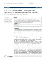
Figure 7 depicts the fixture sealing arrangements to
thoroughly block the etchant. Firstly, the screw threads
of the fixture are wound around using Teflon sealing
tape. Following, the gasket inserting foils laminate is
placed in the fixture. The fixture is then tightly locked.
Finally, all contact surfaces are completely sealed with
AB glue.
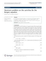
Figure 8 is the cross section SEM image of the upper
aluminum foil under the leakage blocking experiment.
The bi-directional porous array still can be observed.
It conflicts with the leakage hypothesis.
Triplex foils laminate experiment
Figure 9 shows the setting up of the triplex laminate
foils. Under the leakage hypothesis, the etchant should
leak into both the interfacing surfaces between foils.
Therefore, the porous array should be observed on
both the middle and bottom foils. The SEM images of
the top surfaces of the middle and bottom foils are
presented in Fig. 10a and b, respectively. It is observed
that the porous array only grew on the middle foil
(Fig. 10a). No pore appears on the bottom foil.
The triplex laminate foils experiment once again
contradicts the leakage hypothesis.
The bi-directional growing mechanism
Both the leakage blocking and triplex foils laminate
experiments disprove our intuitive leakage hypothesis
of the bi-directional grown of pores, which was
reported elsewhere [11]. Therefore, the upward porous
by the laminate foils approach should be caused by
another mechanism. We greatly appreciate one of
reviewers’ comments that the bi-directional growth
results from the non-uniform anodization along the
sample surface. Fast anodization of selected areas
results in the formation of leakage pathway.
During anodization, the electrochemical reaction
(oxidation of Al into Al
2
O
3
) occurs on the aluminum/
Fig. 8 The cross section SEM
image of the top aluminum
foil under the leakage
blocking experiment
-
Gasket inserting
foils laminate
AB glue
Oring
Cu stick
To anode
AB glue
Al
Front view
Side view
Cross section view
(a)
(a)
(b)
(b)
(c)
(c)
Fig. 7 Schematic illustration
of the fixture sealing
arrangements
To anode
Etchant
Etchant
leaking
Triplex
foils laminate
Etchant
leaking
Fig. 9 Triplex foils laminate
123
Nanoscale Res Lett (2007) 2:49–53 51
barrier layer interface, pushing the barrier layer
downward. When the rate of alumina dissolution on
the electrolyte side equals to the rate of alumina
production on the metal side, the thickness of the
barrier layer remains constant. It can be further
inferred from the experimental results that the
anodization process along the sample surface is
non-uniformed. Due to the nonuniformity of the
thickness or material properties of the original alumi-
num foil, some areas are anodized fast than the rest of
the areas. The fast oxidized areas create a pathway for
leakage, allowing porous-type anodization from the
back side.
Closely examining on the interpore distance on both
the front and back sides may provide further evidence
to the above inference. There is a relatively linear
relationship between the interpore distance and anod-
ization voltage. The high resistance of the leakage
pathway results in a small anodization voltage from the
back side and small interpore distance.
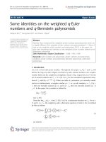
Based on the non-uniformed anodization inference,
the bottom porous array may possesses capsule-like
structure before it reaches the laminate interface. To
further verify this inference, the processing duration is
reduced from eight hours to six hours. The remaining
aluminum is then etched off with etchant CuCl
2
Á HCl.
Figure 11 is the cross section SEM image of the
processing time reducing anodization. The expected
capsule-like structure confirms the non-uniformed
anodization inference.
Conclusion
A bi-directional porous array in an alumina membrane
can be produces by the laminate foils approach. It was
intuitively inferred that leakage of etchant between the
foils may be a feasible cause to have the upward pores
grow in the notches of the unpolished surface. The
intuitive leakage hypothesis is disproved by the leak-
age blocking and triplex laminate foils experiments
being conducted in this research.
It is further inferred that the nonuniformity of the
thickness or material properties of the aluminum foil
induces unequal anodization rate along the sample
surface. The fast oxidized areas produce a pathway for
leakage, allowing porous-type anodization from the
back side.
This non-uniformed anodization inference has been
verified by the anodization time reducing experiment.
Acknowledgements The authors would like to express their
gratitude to the reviewers for their valuable comments and
suggestions. The authors also would like to thank the National
Science Council of Taiwan, for financially supporting this work
under Contract No. NSC-94–2212-E-005–010. The Center of
Nanoscience and Nanotechnology at National Chung-Hsing
University, Taiwan, is appreciated for use of its facilities.
References
1. S.K. Hwang, J. Lee, S.H. Jeong, P.S. Lee, K.H. Lee,
Nanotechnology 16, 850–858 (2005)
2. W.J. Yu, Y.S. Cho, G.S. Choi, D. Kim, Nanotechnology 16,
S291–S295 (2005)
Fig. 11 The cross section SEM image of the nano-capsule array
Fig. 10 SEM images of the
triplex foils laminate
experiment (a) Middle foil (b)
Bottom foil
123
52 Nanoscale Res Lett (2007) 2:49–53
3. T. Yanagishita, K. Nishio, H. Masuda, Adv. Mater. 17(18),
2241–2243 (2005)
4. L. Kim, S.M. Yoon, J. Kim, J.S. Suh, Synthetic Met. 140,
135–138 (2004)
5. E.J. Bae, W.B. Choi, K.S. Jeong, J.U. Chu, G.S. Park, S.
Song, I.K. Yoo, Adv. Mater. 14(4), 277–279 (2002)
6. A.P. Li, F. Miller, A. Birner, K. Nielsch, U. Go
¨
sele, Adv.
Mater. 11(6), 483–486 (1999)
7. R. Krishnan, H.Q. Nguyen, C.V. Thompson, W.K. Choi,
Y.L. Foo, Nanotechnology 16, 841–845 (2005)
8. S.H. Jeong, K.H. Lee, Synthetic Met. 139, 385–390 (2003)
9. J. Yan, G.V. Rao, M. Barela, D.A. Brevnov, Y. Jiang, H. Xu,
G.P. Lopez, P.B. Atanassov, Adv. Mater. 15(23), 2015–2018
(2003)
10. Z. Sun, H.K. Kim, Appl. Phys. Lett. 81(18), 3458–3460 (2002)
11. G.J. Wang, C.S. Peng, J. Nanosci. Nanotechnol. 6(4), 1004–
1008 (2006)
123
Nanoscale Res Lett (2007) 2:49–53 53