Báo cáo hóa học: "Customizing Multiprocessor Implementation of an Automated Video Surveillance System" potx
Bạn đang xem bản rút gọn của tài liệu. Xem và tải ngay bản đầy đủ của tài liệu tại đây (835.29 KB, 12 trang )
Hindawi Publishing Corporation
EURASIP Journal on Embedded Systems
Volume 2006, Article ID 45758, Pages 1–12
DOI 10.1155/ES/2006/45758
Customizing Multiprocessor Implementation of
an Automated Video Surveillance System
Gary Wang, Zoran Salcic, and Morteza Biglari-Abhari
Department of Electrical and Computer Engineering, University of Auckland, Private Bag 92019, Auckland 1142, New Zealand
Received 11 December 2005; Revised 4 July 2006; Accepted 12 July 2006
Recommended for Publication by Leonel Sousa
This paper reports on the development of an automated embedded video surveillance system using two customized embedded
RISC processors. The application is partitioned into object tracking and video stream encoding subsystems. The real-time ob-
ject tracker is able to detect and track moving objects by video images of scenes taken by stationary cameras. It is based on the
block-matching algorithm. The video stream encoding involves the optimization of an international telecommunications union
(ITU)-T H.263 baseline video encoder for quarter common intermediate format (QCIF) and common intermediate format (CIF)
resolution images. The two subsystems running on two processor cores were integrated and a simple protocol was added to realize
the automated video surveillance system. The experimental results show that the system is capable of detecting, tracking, and en-
coding QCIF and CIF resolution images with object movements in them in real-time. With low cycle-count, low-transistor count,
and low-power consumption requirements, the system is ideal for deployment in remote locations.
Copyright © 2006 Gary Wang et al. This is an open access article distributed under the Creative Commons Attribution License,
which permits unrestricted use, distribution, and reproduction in any medium, provided the original work is properly cited.
1. INTRODUCTION
Recent advances of computer technology have made real-
time automated video surveillance possible. Automated
video surveillance can monitor large areas with complex
scenes and can be employed to increase the probability of
specific incident detection and at the same time can reduce
the volume of data presented to security personnel.
Such a system consists of an object detection/tracking
component and a video compression component. Detection
of moving objects in the visible range of a video camera
forms the first stage in automated video sur veillance systems,
and the detection results are used for further processing, such
as object tracking. Video compression is applied to reduce
the storage and communication channel bandwidth require-
ments of the scenes captured.
Various real-time tracking methods such as the differ-
ence technique and block-matching algorithms have been
employed in [1] for real-time object tracking. Although a
parallel hardware implementation of the tracking algorithm
has been proposed in [2], to the best of our knowledge,
there is no performance figure available for the hardware-
implemented object tracker.
Despite the tremendous progress that has been made
in the area of video compression, it remains a challenging
problem due to its computational requirements, especially in
real-time embedded systems. To meet those computational
requirements, various approaches that use dedicated hard-
ware acceleration units, parallel processing, and configurable
processors have been proposed.
Several real-time H.263/MPEG-4 video encoder imple-
mentations have been reported in the past. The real-time
encoding speed of 30 fps for CIF (352
× 288) pictures has
been achieved in [3] using multiple TMS320C6201 DSPs.
H.263/MPEG-4 is suited for parallel processing as it con-
tains both fine-grained and coarse-grained parallelism. Al-
though the use of hardware acceleration units as reported in
[4, 5] can achieve high encoding performance, hardware is
also less flexible and unsuitable for frequent updates when
compared with software only implementations. Recent work
by [6] has achieved real-time M PEG-4 video encoding of the
15 fps QCIF size images requiring 65.7 MCycles using the
same RISC embedded processor as we use in our case. Our
video encoder is able to encode not only 15 fps QCIF but also
CIF images, with lower cycle-count at the cost of extra hard-
ware. It also consumes less power making it more suitable for
low-power applications.
The task of our automated video surveillance system is
essentially to warn an operator when it detects events which
2 EURASIP Journal on Embedded Systems
may require human intervention and compress the captured
video sequence for transmission and storage. In order to re-
duce the amount of video information that is actually trans-
mitted and stored, and to further reduce the power con-
sumption of the system, only bit streams with object move-
ments in them are compressed and stored.
The main contribution of this paper is a fast automated
video surveillance system that is capable of detecting, track-
ing, and encoding QCIF and CIF resolution images in real
time. The system consists of two customized and optimized
processors that will be described in Section 3. Section 2 pro-
vides an overview of the overall surveillance system, which
includes algorithms for object detection/tracking and imple-
mentation of the video compression standard. Section 3 pro-
vides description of implementation of its two major subsys-
tems. The methodology to customize the processor cores to
meet performance requirements is also presented. Section 4
describes building of a multiprocessor solution, simulator for
the multiple processor system-on-chip (MPSoC) system and
its software application. Section 5 presents the results and
discussions followed by conclusions.
2. AUTOMATED VIDEO SURVEILLANCE
The techniques used for object detection and tracking, the
algorithms employed in the video compression task, and the
architectural decisions made in building our video surveil-
lance system are outlined in this section.
2.1. Object detection and object tracking
Detection of moving objects in video sequences can either
be achieved by comparing each new frame with a represen-
tation of the scene background, a process called background
subtraction, or by comparing it with the previous frame us-
ing a block-matching algorithm. Then object tracking is ap-
plied to track the position of a moving object from the video
sequence.
Techniques which use a background model have the ad-
vantage of not being susceptible to textures that do not
move, but have the disadvantage of not being able to de-
tect foreground objects which have similar intensity to the
background. Background modeling techniques can be clas-
sified into two broad categories [7]: nonrecursive and recur-
sive. Nonrecursive techniques require the previous N video
frames to be buffered, and then estimate the background im-
age based on the temporal variation of each pixel within the
buffer. Storage space is required to buffer the frames. Some of
the commonly used nonrecursive techniques include frame
differencing, median filter [8, 9], and nonparametric back-
ground model [10]. Recursive techniques do not need to
buffer a set of frames for background estimation as those
techniques recursively update a single backg round model
based on each input frame. Recursive techniques are mem-
ory efficient, but input frames from distant past could have
an effect on the current background model. So any error in
the background model can linger for a longer period of time.
Some of the commonly used recursive techniques include ap-
Video frames DCT
+
Quantizer
Entropy
encoder
Inv. qu antizer
IDCT
+
+
Frame store
Motion
compensation
Motion estimation
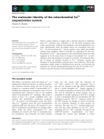
Figure 1: Schematic of the H.263 encoder.
proximated median filter [11], Kalman filter [12, 13], and
adaptive mixture of Gaussians [14, 15].
Block-matching motion estimation algorithms widely
used in video compression applications have also been used
for moving object detection. The determined motion vectors
can be used for object tracking by grouping or associating
some of the motion vectors into a meaningful scene repre-
sentation. Some real-time tracking methods based on block-
matching algorithms have been proposed [1, 16, 17].
2.2. The H.263 encoder overview
The H.263 video compression standard was defined by the
ITU [18] for use in a range of low bit-rate video applica-
tions over wireless and public-switched telephone networks.
A generic H.263/MPEG-4 encoder showing transform and
predictive coding is depicted in Figure 1.Themainopera-
tions that bring about compression include discrete cosine
transform (DCT), inverse discrete cosine transform (IDCT),
quantization (Q), inverse quantization (IQ), var iable length
coding (VLC), and motion estimation (ME).
A compressed video sequence is made up of a series of
INTRA- and INTER-fr ames. An INTRA-frame is used as a
reference frame for INTER-frame encoding. It is coded us-
ing the DCT, Q, and VLC. INTER-frames are coded using
the ME, and built-on INTRA-frames (or previous INTER-
frames) with motion vectors. Thus an INTER-frame is not
viewable on its own. In situations where the video sequence
features a scene change, motion vectors will not generate a
valid image. Thus to improve error resilience, H.263 coding
standard calls for at least one INTRA-coded frame every 132
frames [19] or when a scene change takes place.
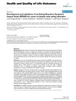
2.3. Overall flow of the automated video
surveillance system
Object tracking using both the background subtraction and
block-matching-based approaches have been modeled and
evaluated to determine which one is the most appropriate
for the implementation platform. Flow diagrams of the video
surveillance system using the background subtraction ap-
proach and the block-matching-based approach integrated
Gar y Wang et al. 3
Video
frame
Preprocessing
Background
subtraction
Postprocessing
No. of
objects > 0
Video encoder
False
True
(a)
Video
frame
Motion
estimation
Postprocessing
No. of
objects > 0
Video encoder
False
True
(b)
Figure 2: Flow diagram of the automated video surveillance system (a) using the background subtraction approach, ( b) using the block-
matching-based approach.
with the video encoder are shown in Figures 2(a) and 2(b),
respectively.
In both cases, the video encoder blocks will only execute
if at least one object has been detected in the scene.
The video surveillance system using the background sub-
tract ion approach works as follows. The video frame cap-
tured and stored in a temporary buffer is preprocessed to
remove noise which enables more accurate object detection.
The background model is then updated using one of the non-
recursive or recursive techniques before subtraction of the
current v ideo frame with the background model, followed
by thresholding of the result to create a binary image. Post-
processing is carried out on the segmented objects to reject
false positives. If an object of interest has been detected in
the frame, the video encoder starts executing by reading the
same video frame from the buffer; otherwise the content in
the buffer can be replaced by the next video frame. The only
data common to both applications is the input video frame.
This method of implementing the object tracker does not al-
low the benefits offered by the SIMD DSP architecture, which
is available as configuration feature of the used customizable
processor, to be fully utilized due to the fact that it operates
at the pixel level across different frames and it requires more
frames to be buffered for nonrecursive techniques.
The flow diagram of the video surveillance system us-
ing the block-matching-based approach integrated with the
video encoder is shown in Figure 2(b). The reference frame
for the object tracker is simply the previous frame, whereas
the reference frame for the video sequence encoder is the re-
constructed frame stored in the frame store. Since the object
tracker processes every frame and the video encoder runs
only when an object is detected, their reference frames are
likely to be different most of the time; so two motion estima-
tion blocks (one for the object tracker and the other in the
video encoder) are required.
3. IMPLEMENTATION
This section describes briefly the processor core that has
been used in our application and the implementation
through processor c ustomization of individual components
that comprise the automated video surveillance application.
3.1. Xtensa configurable processor core
Tensilica’s Xtensa processor [20] is a configurable, extensi-
ble, and synthesizable processor core which can be easily
customized and integrated into system-on-chip (SoC) de-
signs. The Xtensa base architecture includes a 32-bit ALU,
as many as 64- and 32-bit general-purpose registers, and 80-
base instructions, including 16- and 24-bit RISC instruction
encoding with combined branch instructions, such as com-
bined compare-and-branch and zero-overhead loops. SoC
designers can add application-specific instructions to define
new registers, register files, execution units, and custom data
types using the Tensilica Instruction Extension (TIE) lan-
guage. Using the Xtensa processor generator; designers can
also add Vectra DSP engine extensions. Xtensa is supported
with five main development tools, including a GNU-based
software-development suite, the XCC (Xtensa C/C++ com-
piler), the instruction set simulator (ISS) and Xtensa model-
ing protocol (XTMP) API, the TIE compiler, and the mentor
graphics X ray debugger. The ISS provides information on
the contents of the registers in use and the output available
at the processor interface, and the profiling tool measures the
number of clock cycles spent performing specific tasks.
4 EURASIP Journal on Embedded Systems
Table 1: Comparison of performance with and without software optimizations.
Function
Unoptimized (GCC-o0) Optimized (GCC-o3) Speed-up
Cycle-count (MCycles) Percentage Cycle-count (MCycles) Percentage ratio
DCT 1129.09 55.90% 20.31 7.15% 55.60
IDCT
271.06 13.42% 6.92 2.44% 39.17
ME
465.14 23.03% 105.44 37.11% 4.41
Q
54.93 2.72% 55.36 19.48% 0.99
IQ
2.61 10.13% 2.79 0.98% 0.94
VLC
10.41 0.52% 6.55 2.30% 1.59
Others
86.59 4.29% 86.77 30.54% 1.00
Encoder
2019.84 100.00% 284.14 100.00% 7.11
3.2. Implementation of the H.263 video encoder
Our methodology consists of optimizing the most computa-
tionally intensive software functions with more efficient algo-
rithms, selecting the Xtensa processor with different config-
urable coprocessor core options, and adding new specific in-
structions to improve the performance. This is done through
estimating the performance of the encoder after each cus-
tomization (such as adding new instruction to the ISA) is
implemented. The software encoder to be optimized is ver-
sion 1.7 of the TMN (test model near-term) encoder from
Telenor R&D [21] which is compliant with the ITU-T H.263
baseline recommendation, with motion vector not allowed
to point outside image borders. PB-frames (bidirectionally
predicted frames) are not used.
Table 1 shows the profile information of the H.263 en-
coder for the container video sequence [22]inQCIFreso-
lution at bit rate of 64 kbps and frame rate of 15 frames per
second (fps) without any optimizations using the Xtensa V
base processor. The results are collected by the Xtensa ISS.
It is evident that the most computationally intensive func-
tions are DCT and IDCT. The application was compiled by
the GNU C compiler (GCC) and the highest compiler opti-
mization level (-o3) was used to improve the performance.
This resulted in approximately 43% performance improve-
ment compared with no compiler optimization.
Optimization techniques used to reduce the computa-
tional requirements of the H.263 video encoder can be clas-
sified into two classes: software optimizations such as using
more efficient algorithms coded in programming language C,
and architectural optimizations specific to the Xtensa proces-
sor core that is being used for the encoder implementation.
3.2.1. Software optimizations
The profile information shown in Tabl e 1 has identified DCT
and IDCT as the most compute intensive func tions as both
functions operated on floating-point number variables. DCT
and IDCT funct ions are optimized with a fast algorithm
[23]basedon[24, 25] that carry out operations by using
fixed-point numbers. Fixed-point operations along with a
fast DCT algorithm have improved DCT and IDCT perfor-
mance by ratios of 55.6and39.2, respectively, as shown in
Table 1.Thetradeoff in using the new DCT/IDCT algorithm
is that Q and IQ functions take slightly longer, as the DCT
algorithm generates fewer zero valued DCT coefficients. As
a result, more nonzero coefficients need to be quantized and
dequantized, and fewer runs of zeros enter the VLC. How-
ever, the impact on performance is insignificant as the mod-
ulus 64 operations in the VLC function were replaced with a
faster in-lined function which subtracts 64’s to compute the
remainder. The new VLC function executes 1.59 times faster
than the original one.
For motion estimation we selected an in-house devel-
oped algorithm [19] which uses two-step search (2SS) on
12
× 12 pixel blocks to determine motion vectors w ithout
compromising performance. This can lower the contribution
of the ME function by up to five times when compared to full
search algor ithms.
Besides the algorithmic optimizations, efforts were made
to reduce copying large amounts of data around (which con-
stitutes the major part of “Others” row in Tabl e 1). Instead of
copying arrays of data, whenever possible they were replaced
with pointers, which are more efficient in terms of speed and
memory usage.
3.2.2. Processor configuration
The Xtensa processor’s configuration options include mul-
tipliers and multiply-accumulate units (MACs), a floating-
point unit, variable processor-interface (PIF) width (32, 64,
or 128 bit), big- and little-endian byte ordering, DSP en-
gines, memory-management options, local data and instruc-
tion caches, and separate ROM and RAM areas.
In our design, the video encoding processor has been
configured with the Vectra V1620-8 DSP engine, which uses
an 8-way single instruction multiple data (SIMD) architec-
ture and has four 16
× 16 multiply, and 40-bit accumulate
MAC units. The core was also configured with a 128-bit PIF,
which is critical for the memory interface performance.
Gar y Wang et al. 5
3.2.3. Machine-specific optimizations with TIE
Processor extensions created with the TIE language utilize
two basic code-optimization methods: reduce execution cy-
cles by combining multiple operations into one TIE instruc-
tion and reduce execution cycles by operating on multiple
data elements simultaneously (SIMD). A substantial reduc-
tion in the required number of operations can be made by
using the combination of TIE and the Xtensa processors 128-
bit maximum bus width. The encoder which requires many
data reads and writes from memory between various blocks
shown in the diagram in Figure 1. By configuring the proces-
sor with a 128-bit bus width, time spent on copying arrays of
data between the main func tions can be reduced as it is able
to load or store 128 bits at a time.
The addition of TIE instructions can lead to higher per-
formance of the application; however, adding TIE instruc-
tions may incur an increase in the latency of the processor,
which reduces clock frequency. Since the simulator only con-
siders cycle-count as the performance measurement of an ap-
plication, thus care was taken to ensure that instr uctions that
require more than one clock cycle to complete execution are
defined as multicycle TIE instructions.
DCT and IDCT coefficients are computed using the DSP,
which is capable of carrying out additions on eight pixels
or multiplications on four pixels simultaneously. The Vec tra
DSP engine’s architecture allows data, coefficients, and in-
termediate results of the DCT and IDCT algorithms to be
maintained in the vector registers. For both DCT and IDCT
computations, once all 64 input values have been loaded into
the DSP engine over the Xtensa 128-bit data bus, the data
required for the computation are kept in the vector regis-
ters until the output values have been computed and are
ready to be written into memory, thus reducing memory
bandwidth requirements, which improves a pplication per-
formance. A significant number of clock cycles are spent per-
forming zigzag scanning of DCT coefficients. Performance of
reordering data in arrays has been improved by carrying out
the operation in hardware. The new TIE instruction is able
to reorder 8 elements in 11 clock cycles.
Two separate functions for quantization and coded block
pattern (CBP) bitmask calculation were merged into one.
Since the function for CBP calculation uses quantized DCT
coefficients as input, computation time can be reduced by
eliminating store and load operations when the two func-
tions are merged as the input data required for the CBP func-
tion are already in the DSP’s registers.
The division operation is very costly for fixed-point pro-
cessors. During the quantization process, one division for ev-
ery pixel has to be performed. The division operations have
been replaced with shift operations taking place in the Vec-
tra DSP to reduce the computational complexity. This means
that the quantization factor is limited to values of 2
x
such as
2, 4, 8, or 16.
Motion estimation is performed on only luminance mac-
roblocks and uses sum of absolute difference (SAD) as the er-
ror measure. SIMD SAD hardware capable of executing three
SAD component operations on 16 pixels every clock cycle us-
ing TIE and Xtensa processor’s 128-bit maximum bus width
was added.
When calculating SAD, data from within the search win-
dow is not always aligned on 16-byte boundaries. Since the
Xtensa processor treats an unaligned address as if it was
aligned by ignor ing the least-significant address bits, two TIE
instructions have been added to support unaligned 128-bit
memory references.
Other instructions implemented and a brief description
of each instruction for both the video encoder and the object
tracker can be found in [26].
3.3. Implementation of the object detector/tracker
The pur pose of the object tracker is to identify pixels that
are associated with moving objects from a video sequence.
The implementation should be able to track road vehicles
(i.e., cars, trucks, and motorcycles), but should also be gen-
eral enough to be applied for tracking people or other mov-
ing objects. It is assumed that the video sequences to be pro-
cessed for object tracking are captured by motionless cam-
eras. The object tracker needs to be able to process video
sequences at 15 fps (CIF images) since it is a limitation im-
posed by the video encoder. Two different approaches were
explored during the development of the object tracker: back-
ground subtraction and block matching.
3.3.1. Background subtraction
The first approach taken for object detection is based on
a background modeling and subtraction approach which
uses luminance information only. Although it is argued by
[8, 27] that color is better than luminance at identifying ob-
jects in low-contrast areas and suppressing shadow cast by
moving objects, the increase in complexity is significant as
background modeling techniques maintain an independent
model for each pixel and thus real-time processing may not
be achieved if Y, Cb, and Cr components al l need to be pro-
cessed.
The effectiveness of different noise removal techniques,
background modeling techniques and foreground object ex-
traction techniques were evaluated visually by comparing
output binary images with input images. The criterion for
evaluating different methods is based on the goodness of the
segmented binary image. Meaning that in the segmented bi-
nary image there are no more objects than those present in
the input image, and objects’ size are as close as possible to
their size in the input image.
Spatial noise is reduced in the preprocessing stage using
the Gaussian filtering technique. The 3
×3 Gaussian filter ker-
nel was selected to smooth/blur the luminance component
of the video sequences. The median filtering background
modeling technique was chosen despite its high memory re-
quirement as other techniques mentioned in Section 2 (other
than adaptive mixture of Gaussians which was not tested
due to concerns about its computational complexity) did not
provide satisfactory results. The downside of this method
aroused when it came to optimizing its performance for
6 EURASIP Journal on Embedded Systems
the Vectra DSP. The DSP may not provide much increase
in performance as medians need to be calculated for pix-
els located across several buffers for all the spatial locations.
Thus, it would take considerably longer to update the back-
ground using the median filter than the other two methods.
Foreground objects are then separated from the background
and segmented using local adaptive thresholding technique
[28] and a sequential two-pass, nonrecursive connected
components algorithm [29]. Object sizes obtained during the
component labeling process are used to remove noise in bi-
nary images by applying a size filter.
A problem that the background subtraction techniques
suffer from is the slow speed of object tracking. Profiling re-
sults obtained using the Xtensa ISS showed that real-time ob-
ject tracking cannot be achieved using the background sub-
traction approach as it only delivers performance of 2 fps
when simulated using a 200 MHz Xtensa V base processor.
There are no performance figures for embedded platform
implementations of pixelwise backg round subtraction object
trackers from the literature surveyed. The implementation of
a stationary vehicle detection algorithm [30], which is sim-
ilar to the object tracker as it also maintains a background
model of the observed scene, uses a 600 MHz TMS320C6416
DSP platform and obtained performance of only 2.4fps.The
performance figure provides evidence supporting the suspi-
cion that real-time object tracking cannot be achieved even
with the addition of application-specific extensions. Thus no
machine-specific optimizations with TIE were carried out
and another approach was explored and adopted to track ob-
jects in real-time.
3.3.2. Block-matching-based object tracker
By using this method, real-time visual processing can be
achieved as working at the macroblock level can significantly
reduce the number of operations. Block matching, which is
adopted by many current video coding standards, is the most
popular method among other approaches for motion analy-
sis. The block-matching-based method relies on the assump-
tion that the variation of illumination is slow compared to
the intensity var iations caused by moving objects and that
the fast variations in the spatio-temporal intensity are due to
local motion.
The block-matching algorithm used is the two-step
search algorithm [8]. A structure MotionVector is defined to
store each motion vector and its SAD. A 2-dimensional array
of the MotionVector structure was created to hold motion
vector information for each block from the current frame,
9
× 11 of MotionVector structures for QCIF images, and
18
× 22 MotionVector structures for CIF images. This infor-
mation needs to be stored for analysis of object movements
later.
Two binary images are required: one for the previous
frame, and one for the current frame. Both binary images
have the same dimensions a s the array of MotionVector
structures, and they can only have values 0 or 1. In a single
pass, every MotionVector structure’s SAD value is compared
to an experimentally determined threshold. If a block’s SAD
value is greater than or equal to the threshold and the mo-
tion vector’s x and y components are not equal to zero, then
the block is considered to have motion in it and the corre-
sponding position of the binary image for the current frame
is assigned the value 1, otherwise it is assigned the value 0.
Another pass through the MotionVector array is required
to detect slow moving objects and objects that have become
stationary. This is accomplished with the assistance of pre-
vious frame’s binary image. It looks for the value 1 in the
previous frame’s binary image, and every time the value 1 is
found, it checks the SAD value of the corresponding position
in the MotionVector array. During this pass, the threshold
used for classify ing whether motion exists in the block or not
has been lowered substantially in order to detect slow mov ing
objects and objects that have come to a halt. It works based
on the assumption that if there was an object in the specific
position in the previous frame and it has not been detected
in the current frame during the first pass through the Mo-
tionVector array, then the object would have slowed down or
stopped moving; thus causing the SAD value computed to be
below the first threshold used. The binary image of the cur-
rent image is updated after thresholding in the same manner
as in the first pass. However, this only detects stationary ob-
jects for one frame after it stops moving.
A pass through the binary image of the current frame is
performed to resolve the aperture problem. It assumes that
blocks at an object’s boundary have been detected in earlier
steps and only the interior of the object is missing. Every
block of the binary image of the current frame is scanned,
and the number of neighbors with the value 1 is counted. A
block w ith the value 0 is considered to be the interior block
and assigned the value 1 if four or more of its neighboring
blocks have the value 1.
The same sequential two-pass, nonrecursive connected
components algorithm used in the background subtraction
design is used in this case. This time, instead of finding con-
nected components from 101376 pixels in the binary images
(number of pixels for the luminance component) of CIF im-
ages, only 242 pixels (number of macroblocks) need to be
processed using the block-matching-based object tracking
method. Once the objects have been segmented, the centroid
coordinates of the objects are calculated.
3.3.3. Optimization of the real-time object tracker
Theobjecttrackeronlyneedstobeabletoprocessvideose-
quences at 15 fps (CIF resolution) as the video encoder is ca-
pable of encoding 15 fps. Therefore, the object tracker only
needs to finish processing the current frame before the video
encoder fi nishes encoding the previous frame.
Table 2 shows the profile information of the object
tracker processing 15 frames of a typical CIF resolution video
sequence. From Ta ble 2, it is evident that the most computa-
tionally intensive function is the motion estimation function,
which takes up 94.2% of the processing time required. The
real-time tracking method is based on the block-matching
algorithm, thus some of the optimizations made to the
video encoder can also be applied to the object tracker. The
Gar y Wang et al. 7
Table 2: Performance of object t racker without optimizations.
Function
Unoptimized (GCC-o0)
(MCycles) Percentage
Block matching 561.79 94.15%
Connected component
labeling
4.43 0.74%
Read input image 2.39 0.40%
E valuation of motion
within macroblocks
1.51 0.25%
Others 26.59 4.46%
Object tracker 596.70 100.00%
two-step search motion estimation algorithm was already
used when the application was developed in the Microsoft vi-
sual C++ 6.0 development environment, no further software
optimizations were considered to be necessary as there are
no other compute intensive functions. Machine-specific op-
timizations were made by adding TIE instructions to speed
up the motion estimation function. The TIE instructions that
have been added are 128-bit load and store, and 128-bit un-
aligned load for motion estimation.
Minimal Xtensa processor extensions have been used to
minimize the hardware cost and p ower consumption while
providing sufficient performance. Only the 128-bit PIF has
been configured for the 128-bit memory load and store in-
structions.
4. MULTIPROCESSOR SYSTEM
The previous section described the implementation of the
individual components that comprise the automated video
surveillance application. In this section we discuss the in-
tegration of two heterogeneous processors, building of a
simulator for the MPSoC system, synchronization mecha-
nism adopted, and simulation of a system composed of these
application-specific processors and their applications.
4.1. Xtensa modeling protocol
The Xtensa ISS is an instruction-cycle accurate instruction
set simulation model which is appropriate for simulating and
verifying the behavior of a single Xtensa processor connected
to simple memories. The Xtensa modeling protocol (XTMP)
extends the ISS application progr amming interface (API) to
allow for simulation of designs with multiple processors or
custom hardware devices.
XTMP models communication between cores and de-
vices as transactions, not as sig nals, with a positive effect
on the simulation speed and ease of de velopment of the
model, but it affects the accuracy of the developed model.
The XTMP simulator runs faster than a hardware descrip-
tion language (HDL) simulator as the simulator and device
models written in C do not need to model every signal tr an-
sition for every gate and register.
4.2. System memory map
The automated video surveillance application has two tasks
that are executed on two processors, the object detec-
tion/tracking application runs on core 1 (called u1
s1) while
the video encoding application runs on core 2 (u1
s2). A
shared memory module of 64 kB was created as data is shared
between the processors. When an object has been detected by
the object tracking processor, the raw input pixels need to be
shared w ith the video encoding processor. In the system a
single global address space does not exist; instead two sepa-
rate memor y maps are established and each processor has its
own address space. Each processor has its own pr ivate system
ROM and RAM, and the processors share a common mem-
ory module which appears at different addresses of individ-
ual processors.
The processors and memory modules are connected
via an intermediary object called a connector using the
XTMP
connect() function. The connector is connected to
the cores via the cores’ PIF, and allows multiple cores and
multiple devices to be attached to it. It routes processor
read/write transactions to memories and provides an address
mapping capability. The XTMP
multiAddressMapConnect-
or has been used to define a processor-specific address space
so that each processor can use the same address to access a
different memory module as well as allowing each processor
to use a different address to access a shared memory module.
4.3. Synchronization mechanism
Synchronization is needed to ensure that data and control
dependencies are correctly enforced before a processor per-
forms the next task assigned to it. All synchronization in-
volves waiting, and the two schemes that can be used to wait
are busy wait and block.
The two processors only need to communicate when an
object has been detected by the object tr acking processor as
the video encoding processor will be operating on shared
data; otherwise the object detection processor could over-
write the data before the video encoding processor is finished
with it. Raw pixels of the input video frame are written to the
shared memory by core 1 if an object has been detected in
the scene. The pixels stored in the shared memory are then
read by core 2 into its private memory before encoding it
into an H.263 bit-stream. Core 1 may only proceed to write
to the shared memory if it is informed by core 2 that it has
finished reading data from it. Since it does not take long for
core 2 to complete the read operation, core 1 is expected to
wait for short durations of time so busy wait is the appro-
priate wait scheme for core 1. On the other hand, the block-
ing wait scheme is more appropriate for core 2 as it spends
long periods of time waiting for core 1 to determine whether
there are any moving objects in the scene. As the video en-
coder only encodes video scenes with object movements, de-
pending on the system ’s placement, a considerable amount
8 EURASIP Journal on Embedded Systems
Table 3: Number of bytes of shared data for QCIF and CIF resolu-
tion images.
Video Image resolution
Component
QCIF CIF
Y 25.344 101.376
Cb
6.336 25.344
Cr
6.336 25.344
Tot al (by tes )
38.016 152.064
of time could be spent waiting. It is beneficial for the video
encoding processor to stall while waiting for a considerable
amount of time as the processor could be transited into low-
power mode and energy saving can be made with little im-
pact on performance. A dual-FIFO device connected to the
processors’ Xtensa local memory interface (XLMI) ports that
supports both wait schemes from [31] has been added to fa-
cilitate synchronization.
The 64 kB shared memory is sufficient for QCIF resolu-
tion images as the raw pixels require 38.016 bytes of mem-
ory per frame as shown in Tab le 3. The 64 kB shared mem-
ory is not sufficient to store an entire CIF resolution image
(152 064 bytes) in one transfer, but to reduce hardware costs
a CIF fr ame can be transferred through the 64 kB shared
memory by breaking it into three parts as time taken for syn-
chronization is negligible compared to the time required to
process an entire frame by the object tracker. Data from the
shared memory is accessed using the 128-bit load and store
TIE instructions in the same way as accessing private mem-
ories. The addresses are passed to the 128-bit memory refer-
ence functions when they are called, and the address is auto-
matically updated once an access is complete.
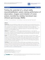
Figure 3 shows the control flow diagr ams of the object
tracker and the video encoder. The flow control used is simi-
lar to the stop-and-wait protocol used in the data-link level of
the open systems interconnect (OSI) model, which requires
the receiver to send an acknowledgment in return for the data
received. Every time the object tracker writes new data to the
shared memory, it waits for an acknowledgment from the
video encoder before writing new data to the shared mem-
ory again. The order over all of the synchronization actions
of an execution for CIF resolution images is as follows.
(1) Core 2 sends the symbol 9 via FIFO1 to inform core 1
that it may write to the shared memory and then stalls.
(2) Core 1 waits until it receives the symbol 9 via FIFO1.
Then, it proceeds to write 64 kB of Y pixels to the
shared memory and sends the symbol 0 via FIFO2 to
notify core 2 that 64 kB of Y pixels is ready to be read.
(3) When core 2 receives the symbol 0 via FIFO2, it reads
64 kB of Y pixels from the shared memory to its private
memory before sending acknowledgment symbol 0 to
core 1 via FIFO1.
(4) After the acknowledgment symbol 0 is received by core
1, it writes 35 kB of Y, 24.75 kB of Cb, and 4.25 kB of
Cr pixels to the shared memory and notifies core 2 by
sending the symbol 1 via FIFO2.
Object tracker
(core 1)
Video encoder
(core 2)
Start
Process frame for
object tracking
Start
FIFO 1
= 9
No. of
objects > 0
False
Encode previous frame
stored in private
memory (if any)
True
False
FIFO 1
= 9
False
FIFO 2
= 0
True
Write 64 kB of Y to
shared memory
FIFO 2
= 0
True
Read 64 kB of Y
from shared memory
FIFO 1
= 0
False
FIFO 1
= 0
False
FIFO 2
= 1
True
Write35kBofY,24.75 kB of
Cb & 4.25 kB of Cr to shared
memory FIFO 2
= 1
True
Read 35kB of Y, 24.75 kB
of Cb & 4.25 kB of Cr from
shared memory FIFO 1
= 1
False
FIFO 1
= 1
True
False
FIFO 2
= 2
Write 20.5kBofCr
to shared memory
FIFO 2
= 2
False
FIFO 1
= 2
True
True
Read 20.5kBofCr
from shared memory
FIFO 1
= 2
Figure 3: Control flow charts of the object tracker and the video
encoder.
(5) When core 2 receives the symbol 1, it reads 35 kB of
Y, 2 4.75 kB of Cb, and 4.25 kB of Cr pixels from the
shared memory to its private memory before sending
acknowledgment symbol 1 to core 1.
(6) After the acknowledgment symbol 1 is received by core
1, it writes 20.5 kB of Cr pixels to the shared memory
and notifies core 2 by sending sy mbol 2 via FIFO2.
(7) When core 2 receives symbol 2, it reads 20.5kBof Cr
pixels from the shared memory to its private memory
before sending the acknowledgment symbol 2 to core
1. Core 2 sends symbol 9 via FIFO1 to inform core 1
that the data in the shared memory is no longer re-
quired and core 2 starts encoding the received frame.
(8) Core 1 waits for acknowledgment from core 2 to con-
firm that the entire frame has been sent before pro-
ceeding to process the next frame.
Gar y Wang et al. 9
Table 4: Comparison of performance without and with TIE optimizations.
Function
Without TIE (GCC-o3) With TIE (XCC-o3)
Speed-up
Cycle-count
Percentage
Cycle-count
Percentage
ratio
(MCycles) (MCycles)
DCT 20.31 7.15% 3.23 6.60% 6.29
IDCT
6.92 2.44% 1.96 4.00% 3.53
ME
105.44 37.11% 20.56 41.99% 5.13
Q
55.36 19.48% 1.20 2.45% 46.13
IQ
2.79 0.98% 0.46 0.94% 6.07
VLC
6.55 2.30% 1.57 3.21% 4.17
Others
86.77 30.54% 19.99 40.82% 4.34
Encoder
284.14 100.00% 48.97 100.00% 5.80
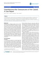
Xtensa V
(core 2)
Video encoding
extensions
PIF
XLMI
Dual-FIFO
device
Xtensa V
(core 1)
Block matching
extensions
PIF
XLMI
Connector
System
RAM 1
System
ROM 1
Shared
memory
System
RAM 2
System
ROM 2
Figure 4: Structure of the multiprocessor system.
The multiprocessor system configuration is show n in Figure
4.
5. RESULTS AND DISCUSSION
The cache explorer has been used to analyze different possi-
ble cache configurations and determine which of them is op-
timal for the application. The H.263 video encoder core was
configured with a direct-mapped, 16 KB instruction cache
with cache line size of 64 bytes and a 2-way set associa-
tive 32 KB data cache with cache line size of 64 bytes. Cache
configuration for the object tracker is not as crucial as the
video encoder is the limiting factor in terms of performance.
Therefore, the object tracker was configured with 8 KB direct
mapped instruction cache with line size of 64 bytes, and 8 KB
2-way set associative data cache with line size of 64 by tes.
The software optimizations and addition of video
compression-specific TIE instructions to the customized
processor core resulted in performance improvement of 41.2
times over the original TMN encoder version 1.7. This im-
provement has allowed real-time H.263 video encoding of
Table 5: Profile information of video encoder compressing QCIF
video sequences with little (first three columns) and substantial (last
three columns) motion (MCycles).
Function
Bridge Bridge
Grandma
Car
Foreman Highway
close far phone
DCT 3.23 3.23 3.23 3.23 3.23 3.23
IDCT
2.94 1.16 0.45 4.23 5.34 3.41
ME
19.79 22.67 19.94 21.11 22.37 22.21
Q
1.20 1.20 1.20 1.20 1.20 1.20
IQ
0.67 0.27 0.10 0.96 1.17 0.77
VLC
1.87 0.73 0.62 3.99 6.53 2.43
Others
19.95 19.31 19.06 20.43 20.94 20.12
Encoder
49.65 48.58 44.61 55.16 60.79 53.37
15 fps QCIF and CIF size images requiring 49 and 205 mil-
lion clock cycles, respectively. Ta ble 4 shows the performance
results for both the software optimized and TIE optimized
encoders. The Xtensa C and C++ compiler (XCC) provides
better execution performance and smaller size of the com-
piled code when compared with the GCC compiler. Among
the slowest operations in ANSI C are copying arrays of data.
These are shown in Ta ble 4 under the “Others” category.
Further results which illustrate performance of the opti-
mized processor for video encoding of some standard video
sequences [22] are shown in Ta ble 5, for QCIF video se-
quences, and in Ta ble 6, for CIF video sequences.
The results shown in Table 7 were obtained using the
standalone Xtensa ISS built for the object tracking proces-
sor. The video sequences with internal names kwbB, rhein-
hafen, taxi, bad,anddtneu-nebel were downloaded from [32]
and resized to 352
× 288 using VirtualDub version 1.65 [33].
Table 5 shows that 15 CIF resolution images can be processed
in 128 million clock cycles for all video sequences tested,
10 EURASIP Journal on Embedded Systems
Table 6: Profile information of video encoder compressing CIF res-
olution sequences (MCycles).
Function Bridge close Bridge far Highway Hall Monitor
DCT 12.95 12.96 12.95 12.95
IDCT
10.18 6.00 12.83 10.02
ME
82.23 98.67 95.01 82.78
Q
4.95 4.95 4.94 4.95
IQ
2.29 1.36 2.87 2.26
VLC
7.89 3.44 8.72 5.18
Others
77.56 75.96 78.51 77.44
Encoder
198.05 203.34 215.83 195.58
Table 7: Profile information of object tracker processing 15 CIF
resolution frames (MCycles).
Function kwbB Rheinhafen Taxi Bad Dtneu nebel
Block matching 84.62 81.09 84.51 95.30 91.59
Connected
component
labeling
0.68 0.55 0.46 0.83 0.35
Output file
generation
(evaluation)
3.04 4.20 4.20 4.62 2.99
Finding motion
within
macroblocks
0.30 0.32 0.66 0.33 0.30
Others 26.88 26.26 26.61 26.56 27.11
Object tracker
115.52 112.42 116.44 127.64 122.34
significantly less than the number of clock cycles required by
the video encoder to encode 15 CIF resolution frames.
The final processor core configurations of both the video
encoder and the object tracker are shown in Tabl e 8.The
200 MHz processor core configured for object tracking has
lower gate count and power dissipation compared to the
205 MHz processor core. This is due to the V1620-8 DSP
configured for the video encoder processor core, which
added approximately 75.000 to the gate count and 34 mW to
power dissipation. The power consumption is an estimation
provided by Xtensa Xplorer tool. It is based on the synthe-
sis results of placed and routed units from library of com-
ponents used in Xtensa processor. An accurate estimation of
power consumption should be done after the physical syn-
thesis of the processor core and running the target applica-
tion.
More TIE instructions also had to be added to the video
encoder application to achieve real-time performance of 15
CIF frames per second. The video encoding core has been
configured with larger instruc tion and data caches, thus ex-
plaining the big difference in area (including caches/local
memories).
Table 8: Video encoding and object tracking processor configura-
tion specifications for standard EDA flow.
Processor Parameter
Core 1 Core 2
Object tracker Video encoder
Process 0.13 µm0.13 µm
Frequency of operation
200 MHz 205MHz
Power dissipation
20 mW 57 mW
Configured processor gate count
40,420 122,900
TIE instruction gate count
13,700 28,042
Area (core only)
0.36 mm
2
1.75 mm
2
Area (including
Caches/Local memories)
1.55 mm
2
4.01 mm
2
Table 9: Clock cycles required by the automated video surveillance
system to process 15 CIF resolution frames (MCycles).
kwbB Rheinhafen Taxi Bad Dtneu nebel
Video encoder 200.19 195.83 198.28 227.27 205.02
Object tracker
187.55 183.09 185.48 212.67 191.61
Entire
application
200.19 195.83 198.28 227.27 205.02
Table 9 shows that the object tracker system requires
more clock cycles to process the frames when it is integrated
with the video encoder. Additional clock cycles are spent by
the processors for synchronization and reading/writing from
the shared memory. With the exception of the bad sequence
which contains a large number of objects, Tabl e 7 shows
that all the sequences can be encoded in less than 205 mil-
lion clock cycles. Calculating an average of the results (some
of which are not shown in Tabl e 7), the automated video
surveillance system requires 195 MCycles to process 15 CIF
resolution frames.
The specification of H.263/MPEG-4 video encoder and
its comparison with the solution from [6] are shown in
Table 10. Our design has a higher gate count figure which
is contributed by the use of the Vectra DSP. Also, it should
be noted that at this processor speed our encoder can handle
CIF images too.
6. CONCLUSIONS
The design of a reactive real-time automated visual surveil-
lance application using the Xtensa platform was presented.
The application is partitioned into object tracking and video
stream encoding subsystems and is executed on two separate
processors.
The video stream encoding subsystem has been real-
ized by optimizing a software H.263 video encoder using
the Xtensa configurable and extensible embedded processor
to provide real-time QCIF and CIF encoding. Experimen-
tal results have shown that performance improvement af-
ter software optimizations and Xtensa-specific optimizations
are 7.1and41.2 times, respectively, when compared with the
Gar y Wang et al. 11
Table 10: Optimized encoder hardware cost.
Our encoder Kim and Kuo [6]
Speed (MHz) 205 MHz 188 MHz
Configured processor gate
count
122,900
+
59,970
∗
TIE instruction gate count 27,000 Not stated
Power consumption
57 mW 98 mW
Area (core only)
1.75 mm
2
1.37 mm
2
Area (including caches/local
memories)
4.01 mm
2
3.17 mm
2
Cycle-count (to encode 15
QCIF frames)
49.0MCycles 65.7Mcycles
+
Cache memories are not included.
∗
Gate count includes TIE instructions but does not include cache
memories.
original TMN encoder. The i mprovement allows encoding
of 15 fps QCIF and CIF while requiring 49 and 205 million
clock cycles, respectively.
The fast and accurate object tracker based on a block-
matching algorithm was successfully tested for different ob-
jects using video sequences taken by motionless cameras.
Some TIE instructions designed for the video compression
application were reused to allow moving objects to be tracked
in real time. The object tracker is able to process 15 CIF reso-
lution frames of the test video sequences in 130 mill ion clock
cycles.
The automated video surveillance application was im-
plemented using two Xtensa cores communicating through
shared memory and synchronized through a dual FIFO. A
multiprocessor simulator program was developed using the
instruction-set simulator API provided by Tensilica for sim-
ulation of the automated video surveillance application on
the multiprocessor system-on-chip architecture. The object
tracking and video stream encoding subsystems’ processor
cores are operating at 200 MHz and 205 MHz, respectively.
The experimental results show that the fast parameter-
ized automated video surveillance system is capable of de-
tecting, tracking, and encoding QCIF and CIF resolution im-
ages in real time.
REFERENCES
[1] S.A.El-Azim,I.Ismail,andH.A.El-Latiff,“Anefficient object
tracking technique using block-matching algorithm,” in Pro-
ceedings of the 9th National Radio Science Conference (NRSC
’02), pp. 427–433, Alexandria, Egypt, March 2002.
[2] I. I. Mahmoud, H. A. Abd El-Halym, and S. E D. Habib,
“Hardware development and implementation of an object
tracking algorithm,” in Proceedings of the 15th International
Conference on Microelectronics (ICM ’03), pp. 330–334, Cairo,
Egypt, December 2003.
[3] O. Lehtoranta, T. H
¨
am
¨
al
¨
ainen, and J. Saarinen, “Parallel im-
plementation of H.263 encoder for CIF-sized images on quad
DSP system,” in Proceedings of IEEE International Symposium
on Circuits and Systems (ISCAS ’01), vol. 2, pp. 209–212, Syd-
ney, Australia, May 2001.
[4] Y C. Chang, W M. Chao, and L G. Chen, “LSI design for
MPEG-4 coding system,” in Proceedings of 47th Midwest Sym-
posium on Circuits and Systems (MWSCAS ’04), vol. 2, pp. 453–
456, Hiroshima, Japan, July 2004.
[5] M.J.Garrido,C.Sanz,M.Jim
´
enez, and J. M. Meneses, “A flex-
ible architecture for H.263 video coding,” Journal of Syste ms
Architecture, vol. 49, no. 12–15, pp. 641–661, 2003.
[6] J G. Kim and C C. Jay Kuo, “MPEG-4 video codec IP de-
sign with a configurable embedded processor,” in Proceedings
of IEEE International Symposium on Circuits and Systems (IS-
CAS ’03), vol. 2, pp. 776–779, Bangkok, Thailand, May 2003.
[7] S C. S. Cheung and C. Kamath, “Robust techniques for back-
ground subtraction in ur ban traffic video,” in Visual Commu-
nications and Image Processing, vol. 5308 of Proceedings of SPIE,
pp. 881–892, San Jose, Calif, USA, January 2004.
[8] R. Cucchiara, C. Grana, M. Piccardi, and A. Prati, “Detect-
ing moving objects, ghosts, and shadows in video streams,”
IEEE Transactions on Pattern Analysis and Machine Intelligence,
vol. 25, no. 10, pp. 1337–1342, 2003.
[9] R. Cutler and L. S. Davis, “View-based detection and anal-
ysis of periodic motion,” in Proceedings of the 14th Interna-
tional Conference on Pattern Recognition (ICPR ’98), vol. 1,
pp. 495–500, IEEE Computer Society Press, Brisbane, Queens-
land, Australia, August 1998.
[10] A. Elgammal, R. Duraiswami, D. Harwood, and L. S. Davis,
“Background and foreground modeling using nonparametric
kernel density estimation for visual surveillance,” Proceedings
of the IEEE, vol. 90, no. 7, pp. 1151–1163, 2002.
[11] N. J. B. McFarlane and C. P. Schofield, “Segmentation and
tracking of piglets in images,” Machine Vision and Applications,
vol. 8, no. 3, pp. 187–193, 1995.
[12] C. R. Wren, A. Azarbayejani, T. Darrell, and A. P. Pentland,
“Pfinder: real-time t racking of the human body,” IEEE Trans-
actions on Pattern Analysis and Machine Intelligence, vol. 19,
no. 7, pp. 780–785, 1997.
[13] J. Heikkila and O. Silven, “A real-time system for monitoring of
cyclists and pedestrians,” in Proceedings of the 2nd IEEE Work-
shop on Visual Surve illance (VS ’99), pp. 74–81, Collins, Colo,
USA, July 1999.
[14] C. Stauffer and W. E. L. Grimson, “Learning patterns of ac-
tivity using real-time tracking,” IEEE Transactions on Pattern
Analysis and Machine Intelligence, vol. 22, no. 8, pp. 747–757,
2000.
[15] C. Stau
fferandW.E.L.Grimson,“Adaptivebackgroundmix-
ture models for real-time tracking,” in Proceedings of the IEEE
Computer Society Conference on Computer Vision and Pattern
Recognition (CVPR ’99), vol. 2, pp. 246–252, Fort Collins,
Colo, USA, June 1999.
[16] K. Hariharakrishnan, D. Schonfeld, P. Raffy, and F. Yassa,
“Video tracking using block matching,” in Proceedings of IEEE
International Conference on Image Processing (ICIP ’03), vol. 3,
pp. 945–948, Barcelona, Spain, September 2003.
[17] K. Hariharakrishnan, D. Schonfeld, P. Raffy,andF.Yassa,“Ob-
ject tracking using adaptive block matching,” in Proceedings of
the International Conference on Multimedia and Expo (ICME
’03), vol. 3, pp. 65–68, Baltimore, Md, USA, July 2003.
[18] ITU-T experts group on very bitrate visual telephony, ITU-T
Recommendation H.263 version 2: video coding for low bi-
trate communication, January 1998.
[19] N. Yu, K. Kim, and Z. Salcic, “A new motion estimation algo-
rithm for mobile real-time video and its FPGA implementa-
tion,” in Proceedings of IEEE Region 10 International Conference
12 EURASIP Journal on Embedded Systems
on Electr ical and Electronic Technology (TENCON ’04), vol. A,
pp. 383–386, Chiang Mai, Thailand, November 2004.
[20] R. E. Gonzalez, “Xtensa: a configurable and extensible proces-
sor,” IEEE Micro, vol. 20, no. 2, pp. 60–70, 2000.
[21] R. Aalmoes, “Roalt’s H.263 Page,” October 2003, http://www
.xs4all.nl/
∼roalt/h263.html.
[22] Arizona State University, “YUV 4:2:0 video sequences,” nd;
/>[23] P. Massimino, “Implementing a Fast D CT/IDCT with SIMD
Instructions,” July 2002.
[24] C. Loeffer, A. Ligtenberg, and G. S. Moschytz, “Practical fast 1-
D DCT algorithms with 11 multiplications,” in Proceedings of
IEEEInternationalConferenceonAcoustics,SpeechandSignal
Processing (ICASSP ’89), vol. 2, pp. 988–991, Glasgow, Scot-
land, May 1989.
[25] Y. Arai, T. Agui, and M. Nakajima, “A fast DCT-SQ scheme for
images,” Transactions of the Institute of Electronics, Information
and Communication Engineers E, vol. E71, no. 11, pp. 1095–
1097, 1988.
[26] G. Wang, “Real-time multiprocessor implementation of an au-
tomated video surveillance application,” ME thesis, The Uni-
versity of Auckland, Auckland, New Zealand, July 2005.
[27]C.R.Wren,A.Azarbayejani,T.Darrell,andA.P.Pentland,
“Pfinder: real-time t racking of the human body,” IEEE Trans-
actions on Pattern Analysis and Machine Intelligence, vol. 19,
no. 7, pp. 780–785, 1997.
[28]B.Fisher,S.Perkins,A.Walker,andE.Wolfart,“Adaptive
Thresholding,” 1994, />thrsh.html.
[29] A. Rosenfeld and J. L. Pfaltz, “Sequential operations in digital
picture processing,” Journal of the ACM, vol. 13, no. 4, pp. 471–
494, 1966.
[30] M. Bramberger, J. Brunner, B. Rinner, and H. Schwabach,
“Real-time video analysis on an embedded smart camera for
traffic surveillance,” in Proceedings of 10th IEEE Real-Time and
Embedded Technology and Applications Symposium (RTAS ’04),
vol. 10, pp. 174–181, Toronto, Canada, May 2004.
[31] Tensilica Inc, Xtensa Instruction Set Simulator (ISS) User’s
Guide (For Xtensa T1050.2 Processor Cores), 2003.
[32] H. H. Nagel, “Institut f
¨
ur Algorithmen und Kognitive Sys-
teme,” nd; />sequences/.
[33] A. Lee, “virtualdub.org,” nd; .
Gary Wang completed his B.E. and M.E.
degrees in computer systems engineering
at the University of Auckland in 2003 and
2005, respectively. His research interests are
in the areas of embedded and real-time sys-
tems and single and multiple processor cus-
tom computing machines.
Zoran Salcic is a Professor of computer sys-
tems engineering at the University of Auck-
land, New Zealand. He holds the B.E., M.E.,
and Ph.D. degrees in electrical and com-
puter engineering from the University of
Sarajevo received in 1972, 1974, and 1976,
respectively. He did most of the Ph.D. re-
search at the City University New York
in 1974 and 1975. He has been with the
academia since 1972, with the exception of
years 1985–1990 when he took the posts in the industrial estab-
lishment, leading a major industrial enterprise institute in the area
of computer engineering. His expertise spans the whole range of
disciplines within computer systems engineering: complex digital
systems design, custom-computing machines, reconfigurable sys-
tems, field-programmable gate arrays, processor and computer sys-
tems architecture, embedded systems and their implementation,
design automation tools for embedded systems, hardware/software
co-design, new computing architectures and models of computa-
tion for heterogeneous embedded systems, and related areas. He
has published more than 180 refereed journal and conference pa-
pers and numerous technical reports.
Morteza Biglari-Abhari received the B.S.
degree from Iran University of Science and
Technology, M.S. degree from Sharif Uni-
versity of Technology in Tehr an, and Ph.D.
degree from The University of Adelaide in
Australia. Currently, he is a Senior Lecturer
intheDepartmentofElectricalandCom-
puter Engineering, the University of Auck-
land in New Zealand. His main research
interests are computer architecture, mul-
tiprocessor system-on-chips, compiler optimizations, and hard-
ware/software codesign of low-power embedded systems. He is also
a Member of t he steering committee of Polymer Electronic Re-
search Centre (PERC) at the University of Auckland. He is also a
Member of IEEE and IEEE Computer Society and Reviewer of sev-
eral technical journals and conferences (such as Journal of Micro-
processors and MicroSystems, EURASIP Journal of Applied Signal
Processing,andonEmbeddedSystems,FPL,VLSI,ISSPA,andEU-
SIPCO conferences).