Báo cáo hóa học: " Using MEMS Capacitive Switches in Tunable RF Amplifiers" ppt
Bạn đang xem bản rút gọn của tài liệu. Xem và tải ngay bản đầy đủ của tài liệu tại đây (1.15 MB, 9 trang )
Hindawi Publishing Corporation
EURASIP Journal on Wireless Communications and Networking
Volume 2006, Article ID 16518, Pages 1–9
DOI 10.1155/WCN/2006/16518
Using MEMS Capacitive Switches in Tunable RF Amplifiers
John Danson, Calvin Plett, and Niall Tait
Department of Electronics, Carleton University Ottawa, ON, Canada K1S 5B6
Received 15 October 2005; Revised 27 February 2006; Accepted 14 March 2006
A MEMS capacitive switch suitable for use in tunable RF amplifiers is described. A MEMS switch is designed, fabricated, and
characterized with physical and RF measurements for inclusion in simulations. Using the MEMS switch models, a dual-band low-
noise amplifier (LNA) operating at 2.4GHzand5.2 GHz, and a tunable power amplifier (PA) at 5.2 GHz are simulated in 0.18 μm
CMOS. MEMS switches allow the LNA to operate with 11 dB of isolation between the two bands while maintaining 11.6dBofgain
and sub-4.5 dB noise figure. MEMS switches are used to implement a variable matching network that allows the PA to realize up
to 37% PAE improvement at low input powers.
Copyright © 2006 John Danson et al. This is an open access article distr ibuted under the Creative Commons Attribution License,
which permits unrestricted use, distribution, and reproduction in any medium, provided the original work is properly cited.
1. INTRODUCTION
The current push towards smaller devices in wireless tech-
nologies is driving the development of more highly inte-
grated, low-power radios. The desire for interoperability be-
tween different networks requires that multiple-standard ra-
dios be implemented in a single product.
There are obvious advantages to having a product that
operates in both bands. However, this presents a challenge to
designers seeking to reduce chip area. Many radios use sep-
arate receive and transmit chains, duplicating circuitry for
each band of operation. Unfortunately, there are few alterna-
tives using tr aditional circuit techniques.
Micro-electrical-mechanical systems (MEMS) offer the
circuit designer new possibilities for including high-per-
formance tuning and switching elements in their designs.
MEMS are mechanical structures built directly on a substrate
using processes similar to those used in IC fabrication.
RF MEMS devices find applications in a variety of areas,
including filter tuning, phase shifters, reconfigurable match-
ing networks, receive/transmit switches, and duplexers. De-
vices range from tunable capacitors and integrated inductors
to mechanical and acoustical resonators [1].
OnetypeofMEMSdeviceisacapacitiveswitch.Thispa-
per outlines the operation of the switch and describes a de-
sign procedure for the switch, with emphasis on integrating
the device into a standard IC design from a circuit designer’s
point of view. A MEMS switch is designed and character-
ized for use in simulations of a dual-band low-noise amplifier
(LNA)andatunablepoweramplifier.
2. MEMS CAPACITIVE SWITCHES
2.1. Device overview
There are many different types of MEMS switches in both se-
ries and shunt configurations [2].TheseswitchescanbeDC
contact switches, where there is direct metal contact between
the two plates or capacitive switches as discussed below.
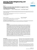
MEMS capacitive switches are fabricated with a metal-
dielectric-air gap-metal cross section as shown in Figure 1.
The upper metal plate (also known as a bridge) can be ac-
tuated from an up state to a down state. In the up state, the
plate is relaxed and the air gap is present between the dielec-
tric and the upper plate. In the down state, an electrostatic
force is applied by an external control voltage to the upper
plate causing it to collapse and eliminating the air gap be-
tween the dielectric and upper plate. Capacitance ratios be-
tween the two states of 600 : 1 are attainable [3] although
30–40 : 1 is more typical.
Due to the mechanical nature of the switches, the fre-
quency response of the bridge follows a lowpass charac ter-
istic with a mechanical resonance in the range of 10–200 kHz
[4]. Although the switching speed of MEMS sw itches is rela-
tively low compared with active devices, they offer the advan-
tage of very low static power dissipation. MEMS switches still
face challenges in the areas of reliability and packaging to be
competitive, however their wide tuning range allows for new
circuit topologies.
The actuation voltage of a MEMS switch is determined by
equating the electrostatic force of the applied voltage to the
mechanical restoring force of the beam. This is dependent
2 EURASIP Journal on Wireless Communications and Networking
Substrate
l
2
l
2
w
c
Lower plate
Dielectric
g
0
t
ox
t
Air gap
Upper plate
Figure 1: MEMS capacitive switch cross section.
on the spring constant, k, for a fixed-fixed bridge as shown
in Figure 1
k
=
32Et
3
w
l
3
,(1)
where E is Young’s modulus, t is the bridge thickness, w is
the bridge width, and l is the bridge length over which the
electrostatic force is applied. In the case of the switch shown
in Figure 1, the electrostatic force is applied over the two
ground planes on either side of the center conductor, denoted
by l/2. The actuation voltage is g iven by [4]
V
sw
=
2k
0
A
g
2
g
0
− g
,(2)
where g
0
is the bridge height in the up state (at 0 V bias), g
is the current beam height, and A
= wl is the area of the
bridge that overlaps the lower-ground plane. Equation (2)
shows that there are two possible voltages for ever y bridge
height. This is due to the instability that occurs when the
electrostatic force exceeds the restoring force. At this point,
the bridge pulls down. This instability occurs at a bridge
height of [4]
g
=
2
3
g
0
. (3)
Knowing the bridge height, and substituting for k and A,
the pull-down voltage can be determined [4]:
V
p
= V
sw|
(2/3)
g
0
=
256Eg
3
0
t
3
27
0
l
4
. (4)
The pull-down voltage must not exceed the breakdown
voltage of the dielectric layer, therefore limiting the thickness
and type of the dielectric material. The pull-down voltage is
also important to circuit designers as it determines what type
of actuation circuitry is required. The dielectric thickness
previously set to avoid breakdown imposes a maximum ca-
pacitance density. This allows the circuit designer to deter-
mine the maximum practical capacitance given the standard
die area trade-offs of large on-chip passives such as MIM caps
and spiral induc tors.
A further consideration is the potential for nonlinearity
in the switch. Two RF tones separated by a frequency below
the resonant frequency of the switch create an envelope effect
that act s to modulate the air gap in the switch, hence chang-
ing the capacitance. Careful design to increase the bridge
spring constant can mitigate this problem. It should be noted
that MEMS switches are still more linear than diode or FET-
based devices [5].
2.2. Switch design procedure
Given the main parameters of interest to the circuit designer,
a typical design procedure can be proposed for a MEMS ca-
pacitive switch. The primary goal of the design procedure is
to provide the circuit designer with a simple set of param-
eters, while avoiding the level of detail that is generally the
domain of the device engineer. Along with this simple set of
parameters, an accurate RF model of the device, such as those
in [6, 7], is clearly required.
2.2.1. Identify type of implementation
Ideally, the devices would be postprocessed on the die con-
taining the active devices. This may not be practical due to
die handling limitations, particularly for prototype designs.
For proof-of-concept designs, the MEMS switches may be lo-
cated on a separate die, then wire bonded to the active device
die. However, the effect of the bond wire inductance must be
included and it may constrain circuit topologies.
2.2.2. Determine size ratios
Size ratios between the two capacitances are determined in
conjunction with the circuit design. Although the typical ca-
pacitance ratio for a MEMS switch is in the 30–40 : 1 range,
this may be too high. In cases where a smaller ratio is desired,
the switch dimensions can be adjusted or a fixed capacitance
can be added in parallel w ith the switch.
2.2.3. Size capacitor and allocate chip area
The circuit designer must determine how much chip area
can be devoted to the switch. Given the maximum pull-down
voltage that can be implemented by the control circuitry, the
maximum capacitance density can be found from the min-
imum dielectric thickness that will not break down. Along
with the chip area, the maximum capacitance density limits
the size of capacitor that can be realized.
2.2.4. Adjust switch for linearity
Finally, the bridge width must be adjusted for adequate lin-
earity. By substituting the spring constant, shown in (1), into
the expression for actuation voltage, it can be seen that while
spring constant is proportional to bridge width, actuation
voltage is independent of bridge width. Since the capacitance
between the bridge and the signal conductor dominates the
device capacitance, the conductor w idth can be adjusted to
compensate for any change in capacitance caused by chang-
ing the bridge width.
A spring constant k>10 N/m was determined in [5]to
be practical for most designs, however it may be higher than
necessary for a given circuit. A more complete device model
for the MEMS switch that includes dynamic response would
allow the circuit designer to adjust the bridge width as neces-
sary. The dynamic model would incorporate the mechanical
force balance equations, the high-frequency electrical re-
sponse, and the low-frequency interaction between the two.
John Danson et al. 3
Actuation contact
Ground
Signal
Ground
Bridge
Figure 2: Die photo of a MEMS capacitive switch.
2.3. Experimental results
Using the design procedure above, a set of MEMS capacitive
switches has been designed for use in the dual-band LNA de-
scribed in Section 3. A die photo is shown in Figure 2.
As shown in the die photo, the switches are designed in
a coplanar waveguide configuration to facilitate testing and
integration with the active circuitry. The switch geometry is
based on a common fixed-fixed bridge as reported in the lit-
erature. The upper plate, or bridge, at center is controlled
through the actuation voltage contact at the top of the figure.
Signal and ground lines form the lower plate. The bridge is
perforated with a grid of holes to allow the sacrificial spacer
material to be etched away.
TheMEMSswitchesarebasedonaprocessdeveloped
at Carleton University and built in Carleton’s Microelectron-
ics Fabrication Lab [8]. The switches use aluminum metal-
lization and an organic sacrificial spacer (Shipley S1811 pho-
toresist) in a 4-mask process. Both the metallization and di-
electric deposition are performed at low temperature, and
the sacrificial spacer does not require an aggressive release
etch (solvent or oxygen plasma only). Hence, the MEMS pro-
cess is adaptable to postprocessing on most substrates, so the
switches would ideally be postprocessed directly on the RF
wafer.
Due to die handling constraints, the MEMS switches for
the circuits described in Section 3 are designed to be built on
a separate die, then wire-bonded to the active circuitry using
chip-on-board. Although one of the motivations for this re-
search is to reduce chip area, building the switches on a sep-
arate die actually increases area because of the extra bond-
pads required to connect the dice. Dimensions of the MEMS
switch are listed in Tabl e 1.
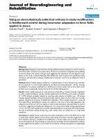
The switches are examined under a WYCO MHT-III op-
tical profiler to check for any anomalies from fabrication. A
plot of a switch in the down state is shown in Figure 3.The
small deformity along the center of the bridge indicates some
residual stress from fabrication.
The switches have a pull-down voltage of 3.8V,whichis
higher than the 1 .8 V CMOS supply voltage. A separate sup-
ply would be required to actuate these part icular switches,
however there are alternate design techniques that allow the
pull-down voltage to be lowered. For the proof-of-concept
designs presented in Section 3, this pull-down voltage was
deemed to be acceptable.
Table 1: Dimensions of the MEMS switch.
Parameter Dimension
Bridge thickness, t (μm) 1
Bridge width, w (μm)
310
Bridge length where force is applied, l (μm)
370
Bridge height at 0 V bias, g
0
(μm) 1.7
Dielectric thickness, t
ox
(μm) 100
Signal conductor width, w
c
(μm) 100
−1
0
1
×10
−5
800
600
400
200
0
1000
800
600
400
200
0
Z (m)
X (um)
Y (um)
Figure 3: 3D surface plot of a MEMS sw itch in the down state.
The switches use silicon nitride (
r
= 7.5) for the dielec-
tric layer. The physical dimensions were selected to provide
a capacitance ratio of 8 : 1, however bond wire inductance
reduced the effective capacitance ratio to 6 : 1. This is less
than optimal for the LNA, but still produces acceptable in-
band gain. The bridge width meets the condition for linear-
ity with a spring constant of 13.7 N/m. Capacitance measure-
ments are shown in Figure 4. At the frequencies of interest
for the LNA design, the switches have a Q of 25 at 2.4GHzin
the down state and a Q of 77 at 5.2 GHz in the up state. This
was incorporated in two simple series R-L-C lumped element
models (one at 2.4 GHz and the other at 5.2 GHz) fitted to
the measurements for inclusion in the LNA simulations.
3. APPLICATIONS
This section describes two circuits that use MEMS capacitive
switches and are designed using the design procedure out-
lined above. The first is a dual-band LNA that operates in the
2.4GHz and 5.2 GHz wireless LAN bands. The second is a
tunable power amplifier at 5.2GHz for improved efficiency
at lower input power.
3.1. Dual-band low-noise amplifier
A proposed dual-band LNA circuit is shown in Figure 5.The
LNAistooperateat2.4GHzand5.2 GHz and to be built in
a0.18 μm CMOS process using MEMS capacitive switches.
4 EURASIP Journal on Wireless Communications and Networking
1234567 8910
280
290
300
310
320
330
Capacitance (fF)
Frequency (GHz)
Measured
Fitted model
C
up
1234567 8910
1
2
3
4
5
Capacitance (pF)
Frequency (GHz)
Measured
Fitted model
C
down
Figure 4: RF measurements and fitted data for a MEMS switch.
In +
L
g1
C
g
L
g2
L
s
M1
In
−
Out+
MEMS capacitive
switches
V
DD
L
tank
C
MEMS
Out−
M2
V
CTRL
Figure 5: Simplified LNA schematic (bond pads/wires, ESD, and biasing are not shown).
Tunable LNAs have some distinct advantages over their
fixed counterparts. They offer the ability to change the oper-
ating frequency of the amplifier by adjusting matching and
resonant tank circuits.
There are different methods to tune LNAs, all of which
have limitations. Multiple FETs can be used to select between
fixed capacitors to increase or decrease the capacitance on
a particular node. The disadvantage with this approach is
that the FETs introduce noise into the circuit [9]. The added
channel resistance also limits the range of capacitances that
can be switched into the circuit. Varactors are a different
method of tuning the circuit. The range of capacitance that
can be achieved is limited to the tuning range of the varactor.
These methods are better suited to narrowband tuning of an
LNA as in [10].
For wider-band operation, a different approach is neces-
sary. Several dual-band LNAs are presented in [11–13] that
use a separate LNA circuit for each band. Va rious meth-
ods are used to select the desired band. Although this topol-
ogy does simplify the task of input matching and the tuned
load, it requires twice the number of components. Since on-
chip inductors consume large amounts of chip area, it is de-
sirable to find new topologies that reduce the number of
components.
A concurrent dual-band LNA for operation at 2.45 GHz
and 5.25GHzispresentedin[14]. This LNA uses dual-tuned
circuits for the input match and load to achieve simultaneous
operation at both frequencies. Since the LNA amplifies both
bands concurrently, there is the potential for cross-band
compression and intermodulation.
In the proposed design, a cascode topology is used to
achieve the desired gain at both frequencies and for isola-
tion between the input matching and the tuned tank. This is
important since switching the tuned tank of a simple com-
mon source amplifier would present a significantly different
impedance at the amplifier input. The differential design lim-
its packaging effects from bond wire inductance.
There are several different circuits that yield a good in-
put match at both frequencies, some using MEMS switches
and some using dual-tuned circuits. With the switches being
fabricated on a separate die, many of the switched matching
circuits are not practical. For this reason a dual-tuned cir-
cuit as in [14] is selected for the input matching. With low-
quality factor on-chip inductors, the input matching net-
work contributes to higher noise figure. Postprocessing the
MEMS components offers the advantage that higher Q in-
ductors, not available in the CMOS process, could be in-
cluded.
Inductive degeneration is used to improve linearity, lower
noise figure, and boost the input impedance as discussed in
[15, 16]. The width of the input transistor is increased to
match a 50 Ω source impedance with the dual-tuned circuit.
The cascoding device is made the same width as the input
transistor to allow drain-source sharing, minimizing its noise
contribution.
The cross-band distortion problems are considerably
reduced by using a tuned tank realized with an on-chip
symmetrical inductor and MEMS switches. Since the LNA
only amplifies one band at a time, there is greater isolation
between the two bands.
John Danson et al. 5
11.522.533.54 4.555.56
Frequency (GHz)
−40
−30
−20
−10
0
10
20
S
21
(dB)
11.7 dB
19.5 dB
5.2GHz
2.4GHz
11.522.533.54 4.555.56
Frequency (GHz)
−35
−30
−25
−20
−15
−10
−5
0
S
11
(dB)
5.2GHz
2.4GHz
11.522.533.54 4.555.56
Frequency (GHz)
0
5
10
15
20
25
30
35
NF (dB)
5.2GHz
2.4GHz
Figure 6: Extracted simulations of the LNA showing gain and cross-band isolation, input return loss, and noise figure.
Table 2: Performance comparison with other dual-band LNAS.
Technology
[14] [17] [18] This work
0.35 μmCMOS 0.18 μmCMOS 0.18 μmCMOS 0.18 μmCMOS
Operating bands (GHz) 2.45 5.25 2.45 2.45.2 2.45.2
Gain, S
21
(dB) 14 15.5 11.610.8 10.110.9 12.211.6
Noise figure (dB)
2.34.5 2.32.9 2.93.4 4.54.2
Input return loss, S
11
(dB) −25 −15 −5.1 −26.3 −10.1 −11 −27.6 −8.5
Input P
1 dB
compression (dBm) −8.5 −1.5 −7.9 −7.1 −7 −16 −4.9 −7.6
Cross-band isolation (dB)
1.5 12.517 No data 11.719.5
Input IP3 (dBm)
0.05.6 No data 4 −5 3.13.9
Supply voltage (V)
2.5 1 1.8 1.8
Power consumption (mW)
10 14.2 11.75.7 16.7
Area (mm
2
) 0.64 0.9 No data 1.58
Notes
Concurrent design, FET-switched FET-switched MEMS capacitive
input matching off-chip inductor capacitor switches
Due to parasitic capacitances in the layout from
bondpads and interconnect, the circuit requires a switch ca-
pacitance of C
up
= 200 fF at 5.2 GHz and C
down
= 1.7pF
at 2.4 GHz. This means for optimal performance the MEMS
switch must have an up-down capacitance ratio of 8 : 1.
At 6 : 1, as is the case with the measured switches, opti-
mal gain in the 5.2 GHz band is shifted down in frequency to
4.7 GHz. In the case where the MEMS switches are postpro-
cessed on the CMOS wafer, the bond pad parasitics would
not be present and the capacitance change could be lower
than the optimal 8 : 1 ratio.
Extracted simulations of the LNA, shown in Figure 6,
predict forward gain greater than 11.6 dB for both bands with
sub-4.5 dB noise figure. The forward gain plot in Figure 6
shows a minimum cross-band isolation of 11.7dB for both
bands. The measured model of the MEMS switch is included
in these simulations, along with bond pads, bond wires, ESD
structures, and capacitive parasitics from interconnect. Sim-
ulations show that the LNA is stable a cross frequency. This is
achieved with a power consumption of 16.7mWfroma1.8V
supply. The results are compared with other dual-band LNAs
in Table 2.
3.2. Tunable power amplifier
Theoutputstageofa20dBm,5.2 GHz class AB tunable
poweramplifieristobedesignedina0.18 μmCMOSprocess
6 EURASIP Journal on Wireless Communications and Networking
V
in
L
g
C
g
RFC
RFC
L
match
M1
M2
C
DC
C
DC
R
L
C
MEMS2
C
MEMS1
C
1
L
1
V
GG
V
DD
L
bond wire
Figure 7: Class AB tunable PA.
Z
o
B
2
B
3
B
1
Y
L
= G
L
+ jB
L
Figure 8: Variable matching network represented by susceptances.
using MEMS capacitive switches with a goal of increasing ef-
ficiency over a range of power levels.
ThemaingoalofthisPAistoincreaseefficiency at lower
power levels where the output stage is typically inefficient.
Other methods for increasing efficiency at low power include
dynamically adjusting the power supply voltage [19, 20]or
using parallel amplifiers (such as the Doherty configuration)
[21]. This design is loosely based on a 500 MHz, 100 W PA in
[22]. In that amplifier, PIN diodes are used as switches in an
L matching network to adjust a capacitor bank. This design
uses a similar approach, but tailored for MEMS capacitors.
The proposed PA is shown in Figure 7. The input tran-
sistor, M1, is matched with a lowpass network formed by L
g
and C
g
to limit harmonic content. The source bond wire in-
ductance is modeled with L
bondwire
.Thisisactuallyformed
of several bond wires in parallel to lower the induc tance and
to provide h eat sinking to the die. DC blocking is provided
by the bypass capacitors, C
DC
.Afilter,formedbyL
1
and C
1
,
helps increase efficiency by shunting harmonic power at the
drain to ground. The π network formed by C
MEMS1
, C
MEMS2
,
and L
match
is a variable m atching network that adjusts the
50 Ω load, R
L
, to the optimal load impedance, Γ
opt
, to in-
crease efficiency at lower power.
Since the variable matching network must match to two
different impedances, equations are derived for a π net-
work implemented with a fixed inductor and two variable
capacitors, shown by susceptances B
1
, B
2
,andB
3
in Figure 8.
The equations to relate B
1
, B
2
,andB
3
back to C
MEMS1
,
C
MEMS2
,andL
match
are as follows:
L
match
=
1
2πf
high
B
3
≤
Z
o
R
small
2πf
high
,
C
MEMS1
· 2πf = B
1
=−B
L
− B
3
±
G
L
B
2
3
Z
o
− G
2
L
,
C
MEMS2
· 2πf = B
2
=−B
3
±
1
Z
o
G
L
G
L
B
2
3
Z
o
− G
2
L
,
(5)
where R
small
is the smallest of the two load resistances, and
f
high
is the highest frequency (in the case that the matching
network is being used at two different frequencies). Z
o
is the
load resistance, typically 50 Ω,andY
L
is the complex conju-
gate of Γ
opt
.
To design the amplifier, a series of load pull simulations
are performed over increasing input powers. Due to am-
plifier nonlinearities, optimal output power cannot be ob-
tained by matching to the conjugate of the small-signal out-
put impedance. The load pull simulation sweeps all possible
values of output impedance, then plots contours of constant
power on the Smith chart. An example at 0 dBm is shown in
Figure 9.
As shown in Figure 10, at high input power levels (and
hence higher output power), the optimal load impedance is
mostly resistive with a small inductive component. As the
input power drops, the optimal load becomes more induc-
tive, acting to cancel the drain capacitance as would happen
in the conjugate match of a small-signal amplifier. Based on
the range of optimal loads, two impedances are chosen to
be presented by the variable matching network. The variable
matching network adjusts the load to be more inductive as
the input power decreases by switching the MEMS capaci-
tors. Although there are four possible impedances that can
be presented by the switched network, only two a re used as
shown by the triangles in Figure 10.
Simulations compare the performance of the class AB PA
with a fixed and variable matching network. The P
out
graph
in Figure 11 shows minimal difference between the two net-
works.Thedesigngoalof20dBmoutputpowerisachieved
at an input power of 12.5dBmforagainof7.5dB.
The power added efficiency (PAE) graph shows the ex-
pected increase in efficiency. At P
in
= 0 dBm, there is a
37% increase in PAE over the fixed match. Even at P
in
=
10 dBm, there is still an 8% improvement. There is no
John Danson et al. 7
−0.3
−0.5 −0.7 −1 −1.5 −1.95
−0.2 −1
−3−0.1
0
00.10.5
1
25
0.1
0.2
−0.10.3
3
−0.2
0.50.7
1.5
1.95
−1−0.2
−0.2
−0.1
−10
10
10
Figure 9: A load pull simulation showing constant power contours at 0 dBm input power.
Z
o
= 50 Ohms
− j1
− j2
− j0.5
− j0.2
00.20.512
j0.2
j0.5
j1
j2
P
in
= 12.5dBm
P
in
= 0dBm
Figure 10: Γ
opt
plotted for increasing input power (circles) overlaid with the two chosen loads presented by the variable output matching
network (triangles).
difference in PAE at high input powers where the two match-
ing networks effectively have the same values. The PA is
operating in a strong ly nonlinear mode with an input re-
ferred 1 dB compression point of 4.3 dBm and an input IP3
of 13.9 dBm. Power consumption for P
out
= 15 dBm is
153 mW.
4. CONCLUSION
A design procedure for a MEMS capacitive switch, emphasiz-
ing integration in a standard IC design, has been presented.
The procedure focuses on the circuit designer’ s requirements
for inclusion in new circuit topologies. The design procedure
8 EURASIP Journal on Wireless Communications and Networking
0 5 10 15
P
in
(dBm)
10
12
14
16
18
20
22
P
out
(dBm)
Fixed match
Variabl e match
0 5 10 15
P
in
(dBm)
20
30
40
50
60
70
PAE (%)
Fixed match
Variabl e match
Figure 11: P
out
and PAE for the fixed (optimized for high power only) and variable (optimized for high and low power) matching networks.
is applied to create a MEMS switch for use in a dual-band
LNA. RF and physical measurements characterize the device
for simulation. The LNA is designed in 0.18 μmCMOSto
operate at 2.4GHzand5.2 GHz with for ward gain of 11.6dB
and sub-4.5 dB noise figure for both bands, and with im-
proved isolation between bands. A tunable power amplifier
at 5.2 GHz is also designed in 0.18 μm CMOS using MEMS
switches and realizes a 37% improvement in PAE at lower in-
put powers.
ACKNOWLEDGMENTS
This work is supported in part by the National Sciences
and Engineering Research Council of Canada and Micronet.
CMOS fabrication access was provided by CMC Microsys-
tems.
REFERENCES
[1] J. J. Yao, “RF MEMS from a device perspective,” Journal of Mi-
cromechanics and Microengineering, vol. 10, no. 4, pp. R9–R38,
2000.
[2] G. M. Rebeiz and J. B. Muldavin, “RF MEMS switches and
switch circuits,” IEEE Microwave Magazine,vol.2,no.4,pp.
59–71, 2001.
[3] J. Y. Park, G. H. Kim, K. W. Chung, and J. U. Bu, “Fully in-
tegrated micromachined capacitive switches for RF applica-
tions,” in Proceedings of IEEE MTT-S International Microwave
Symposium Digest, vol. 1, pp. 283–286, Boston, Mass, USA,
June 2000.
[4] G.M.Rebeiz,RF MEMS: Theory, Design, and Technology,John
Wiley & Sons, Hoboken, NJ, USA, 2003.
[5] L. Dussopt and G. M. Rebeiz, “Intermodulation distortion and
power handling in RF MEMS switches, varactors, and tun-
able filters,” IEEE Transactions on Microwave Theory and Tech-
niques, vol. 51, no. 4, part 1, pp. 1247–1256, 2003.
[6] J. B. Muldavin and G. M. Rebeiz, “High-isolation CPW MEMS
shunt switches - par t 1: modeling,” IEEE Transactions on Mi-
crowave Theory and Techniques, vol. 48, no. 6, pp. 1045–1052,
2000.
[7] J. Y. Qian, G. P. Li, and F. De Flaviis, “Parametric model of
MEMS capacitive switch operating at microwave frequencies,”
in Proceedings of IEEE MTT-S Internati onal Microwave Sym-
posium Digest, vol. 2, pp. 1229–1232, Boston, Mass, USA, June
2000.
[8] J. Rose, L. Roy, and N. Tait, “Development of a MEMS
microwave switch and application to adaptive integrated
antennas,” in Proceedings of the IEEE Canadian Conference on
Electrical and Computer Engineering (CCECE ’03), vol. 3, pp.
1901–1904, Montreal, Canada, May 2003.
[9] Z. Li and K. O. Kenneth, “A low-phase-noise and low-power
multiband CMOS voltage-controlled oscillator,” IEEE Jour-
nal of Solid-State Circuits, vol. 40, no. 6, pp. 1296–1302,
2005.
[10] W S. Wuen and K A. Wen, “Dual-band switchable low noise
amplifier for 5-GHz wireless LAN radio receivers,” in Proceed-
ings of the 45th IEEE Midwest Symposium on Circuits and Sys-
tems (MWSCAS ’02), vol. 2, pp. 258–261, Tulsa, Okla, USA,
August 2002.
[11] K. L. Fong, “Dual-band high-linearity variable-gain low-noise
amplifiers for wireless applications,” in Proceedings of the IEEE
International Solid-State Circuits Conference (ISSCC ’99),pp.
224–225, San Francisco, Calif, USA, February 1999.
[12] A. Schmidt and S. Catala, “A universal dual band LNA imple-
mentation in SiGe technology for wireless applications,” IEEE
Journal of Solid-State Circuits, vol. 36, no. 7, pp. 1127–1131,
2001.
[13] M Y. Wang, R. R B. Sheen, O. T C. Chen, and R. Y. J. Tsen, “A
dualband RF front-end for WCDMA and GPS applications,”
in Proceedings of IEEE International Symposium on Circuits
and Systems (ISCAS ’02), vol. 4, pp. 113–116, Scottsdale, Ariz,
USA, May 2002.
[14] H. Hashemi and A. Hajimiri, “Concurrent dual-band CMOS
low noise amplifiers and receiver architectures,” in Proceedings
of the IEEE Symposium on VLSI Circuits, pp. 247–250, Kyoto,
Japan, June 2001.
[15] D. K. ShaefferandT.H.Lee,“A1.5V,1.5GHzCMOSlow
noise amplifier,” in Proceedings of the IEEE Symposium on VLSI
Circuits, pp. 32–33, Honolulu, Hawaii, USA, June 1996.
[16] D. K. Shaeffer and T. H. Lee, “Erratum: a 1.5 V, 1.5 GHz
CMOS low noise amplifier,” IEEE Journal of Solid-State Cir-
cuits, vol. 40, no. 6, pp. 1397–1398, 2005.
[17] T. K. K. Tsang and M. N. El-Gamal, “Dual-band sub-1V
CMOS LNA for 802.11A/B WLAN applications,” in Pro ceed-
ings of IEEE International Symposium on Circuits and Systems
(ISCAS ’03), vol. 1, pp. 217–220, Bangkok, Thailand, May
2003.
[18] L H. Lu, H H. Hsieh, and Y S. Wang, “A compact 2.4/5.2-
GHz CMOS dual-band low-noise amplifier,” IEEE Microwave
Wireless Components Letters, vol. 15, no. 10, pp. 685–687,
2005.
[19] G. Hanington, P F. Chen, P. M. Asbeck, and L. E. Lar-
son, “High-efficiency power amplifier using dynamic power-
supply voltage for CDMA applications,” IEEE Transactions on
Microwave Theory and Techniques, vol. 47, no. 8, pp. 1471–
1476, 1999.
John Danson et al. 9
[20] B. Sahu and G. A. Rincon-Mora, “A high-efficiency linear RF
power amplifier with a power-tracking dynamically adaptive
buck-boost supply,” IEEE Transactions on Microwave Theory
and Techniques, vol. 52, no. 1, part 1, pp. 112–120, 2004.
[21] N. Srirattana, A. Raghavan, D. Heo, P. E. Allen, and J. Laskar,
“Analysis and design of a high-efficiency multistage Doherty
power amplifier for wireless communications,” IEEE Transac-
tions on Microwave Theory and Techniques,vol.53,no.3,pp.
852–859, 2005.
[22] A. C. Cotler and E. R. Brown, “The feasibility of a variable
output matching circuit in a high-power SSPA,” in Proceedings
of IEEE Radio and Wireless Conference, pp. 189–191, Boston,
Mass, USA, August 2002.
John Danson received his B.Eng. and
M.A.Sc. degrees in electrical engineering
from Carleton University, Ottawa, Ontar io,
Canada in 2002 and 2005, respectively. He
has worked with several companies on RF
projects including Nautel, Research In Mo-
tion, and TransCore. As a Member of the
IEEE, his research interests include appli-
cations for MEMS devices in RF integrated
circuits.
Calvin Plett has been with Carleton Univer-
sity, Ottawa, Canada since 1989 and is now
an Associate Professor. Prior to 1982, he
worked for a number of companies includ-
ing nearly four years with Atomic Energy
of Canada, and shorter periods with Xerox,
Valcom, Central Dynamics, and Philips.
From 1982 to 1984, he worked with Bell-
Northern Research doing analog circuit de-
sign. For some years he did consulting work
for Nortel Networks in RFIC design. For the last number of years he
has been involved in collaborative research, with numerous grad-
uate and undergraduate students and various companies includ-
ing Nortel Networks, SiGe Semiconductor, Philsar, Conexant, Sky-
works, IBM, and Gennum. He has authored or coauthored more
than 60 technical papers which have appeared in international jour-
nals and conferences. He is a coauthor of Radio Frequency Inte-
grated Circuit Design and a coauthor for Integrated Circuit De-
sign for High-Speed Frequency Synthesis. His research interests in-
clude the design of analog and radio-frequency integrated circuits,
including filter design, and communications applications. He is a
Member of AES, the PEO, and a Senior Member of the IEEE. He
was the coauthor of papers that won the Best Student Paper Awards
at BCTM 1999 and at RFIC 2002.
Niall Tait received a B.S. degree in engineer-
ing physics from the University of Alberta,
M.A.Sc. degree in physics from University
of British Columbia, and Ph.D. degree in
electrical engineering from the University
of Alberta. In 1992 he joined the Alberta
Microelectronic Center as a Research Scien-
tist working on silicon MEMS and thin film
technology. Since 1997 he has been a faculty
member in the Department of Electronics
at Carleton University working on MEMS and thin film technol-
ogy for RF and microwave applications, sensors, photonics, and
microfluidics.