Báo cáo hóa học: " Multipass Channel Estimation and Joint Multiuser Detection and Equalization for MIMO Long-Code DS/CDMA Systems" potx
Bạn đang xem bản rút gọn của tài liệu. Xem và tải ngay bản đầy đủ của tài liệu tại đây (1.02 MB, 13 trang )
Hindawi Publishing Corporation
EURASIP Journal on Wireless Communications and Networking
Volume 2006, Article ID 24132, Pages 1–13
DOI 10.1155/WCN/2006/24132
Multipass Channel Estimation and Joint Multiuser Detection
and Equalization for MIMO Long-Code DS/CDMA Systems
Stefano Buzzi
DAEIMI, Universit
`
a degli Studi di Cassino, Via G. Di Biasio 43, 03043 Cassino, Italy
Received 8 April 2005; Revised 16 October 2005; Accepted 28 November 2005
Recommended for Publication by Wolfgang Gerstacker
The problem of joint channel estimation, equalization, and multiuser detection for a multiantenna DS/CDMA system operating
over a frequency-selective fading channel and adopting long aperiodic spreading codes is considered in this paper. First of all,
we present several channel estimation and multiuser data detection schemes suited for multiantenna long-code DS/CDMA
systems. Then, a multipass strategy, wherein the data detection and the channel estimation procedures exchange information in
a recursive fashion, is introduced and analyzed for the proposed scenario. Remarkably, this strategy provides, at the price of some
attendant computational complexity increase, excellent performance even when very short training sequences are transmitted,
and thus couples together the conflicting advantages of both trained and blind systems, that is, good performance and no wasted
bandwidth, respectively. Space-time coded systems are also considered, and it is shown that the multipass strategy provides
excellent results for such systems also. Likewise, it is also shown that excellent performance is achieved also when each user
adopts the same spreading code for all of its transmit antennas. The validity of the proposed procedure is corroborated by both
simulation results and analytical findings. In particular, it is shown that adopting the multipass strategy results in a remarkable
reduction of the channel estimation mean-square error and of the optimal length of the training sequence.
Copyright © 2006 Stefano Buzzi. This is an open access article distributed under the Creative Commons Attribution License,
which permits unrestricted use, distribution, and reproduction in any medium, provided the original work is properly cited.
1. INTRODUCTION
Direct-sequence code-division multiple-access (DS/CDMA)
techniques are of considerable interest, since they are among
the basic technologies for the realization of the air inter-
face of current and future wireless networks [1]. One of the
salient features of the emerging CDMA-based wireless net-
works standards is the adoption of long (aperiodic) spread-
ing codes. Even though the use of long codes ensures that
all the users achieve “on the average” the same performance
in a frequency-flat channel with perfect power control, it
destroys the bit-interval cyclostationarity properties of the
CDMA signals and thus renders ineffective many of the ad-
vanced signal processing techniques that have been devel-
oped for blind multiuser detection and adaptive channel esti-
mation in short-code CDMA systems [2, 3]. The design of in-
telligent signal processing techniques for DS/CDMA systems
with aperiodic spreading codes is thus a challenging research
topic.
While most contributions in this area (e.g., [4–7]) ei-
ther propose detection and estimation algorithms with heavy
computational complexity or rely on prior knowledge of the
propagation delay of the user of interest and of the interfering
signature waveforms, in [8] a least-squares channel estima-
tion procedure has been introduced. This procedure relies
on the transmission of known pilot symbols, and it may
be implemented with a computational complexity which is
quadratic in the processing gain, and is suited for both the
uplink and the downlink. The channel estimation procedures
presented in [8] have been also used in [9], wherein a recur-
sive algorithm, based on an iterative exchange of information
between the data detector and the channel estimator, is pro-
posed in order to improve the system performance.
So far, the problem of devising effective channel estima-
tion algorithms for long-code CDMA systems has mainly fo-
cused on the case that the transmitter and the receiver are
equipped with a single antenna, and indeed all the papers
so far cited refer to this scenario. On the other hand, of late
there has been a growing interest in the design and the anal-
ysis of communication systems employing multiple transmit
and receive antennas, also known as multiple-input multiple-
output (MIMO) systems. Indeed, recent results from infor-
mation theory have shown that in a rich scattering environ-
ment the capacity of multiantenna communication systems
2 EURASIP Journal on Wireless Communications and Networking
grows with a law approximately linear in the minimum be-
tween the number of transmit and receive antennas [10–12 ].
In general, the use of multiple antennas has a complicated
impact on the performance of a wireless communication sys-
tem. The use of multiple antennas at the transmitter, in un-
coded systems, permits attaining a wireless communication
link with large spectral efficiency. Otherwise stated, having
N
t
antennas at the transmitter and a ser ial to parallel con-
verter with N
t
outputs, permits transmitting a given symbol
stream with a bandwidth N
t
times smaller than the one re-
quired by a system using the same modulation format and
having only one transmit antenna. In a space-time coded sys-
tem, instead, part of the increase in the spec tral efficiency
may be sacrificed for transmit diversity, which provides in-
creased performance and resistance to fading. The use of
multiple antennas at the receiver, instead, provides a receiver
diversity advantage, since the receiving multiple antennas
provide multiple independently faded replicas of the trans-
mitted signals. This helps to improve performance and, also,
to separate the symbols transmitted by different antennas
through suitable signal processing techniques. Several mul-
tiantenna communication architectures have been thus pro-
posed, formerly for single-user systems [13, 14], and then for
multiuser systems [15, 16]. In particular, the paper [16]de-
velops subspace-based blind adaptive multiuser detectors for
short-code DS/CDMA systems with transceivers equipped
with multiple antennas. Since these subspace-based tech-
niques rely on the symbol-interval cyclostationarity of the
observed data, they are not applicable to CDMA systems em-
ploying long codes.
Following on this track, in this paper we consider the
problem of channel estimation for multiantenna DS/CDMA
systems employing long codes. The contributions of this pa-
per can be summarized as follows.
(i) We extend the iterative channel estimation and data
detection procedure in [9] to the case where each user is
equipped with multiple transmit and receive antennas. It is
thus shown that the iterative strategy permits achieving, at
the price of little attendant computational complexity in-
crease, excellent performance in MIMO systems also for very
short lengths of the training sequence.
(ii) With regard to the problem of channel estimation,
we extend the least-squares channel estimation procedures
of [8] to the case of a multiantenna transceiver.
(iii) We provide a theoretical performance analysis of the
proposed iterative strategy, which leads to a closed-form for-
mula relating the mean square channel estimation error at
each iteration with the error probability achieved by the data
detector at the previous iteration.
(iv) We show that the proposed iterative strategy provides
excellent results also in the case that each user is assigned only
one spreading code, which is thus used to spread the data
symbols on all of its transmit antennas.
(v) The problem of how to set the length of the training
sequence is considered. Indeed, this length should be cho-
sen as a compromise between the conflicting requirements
of achieving a reliable channel estimate and of not reducing
too much the system throughput, that is, the fraction of in-
formation bits in each data packet. A cost function is thus
introduced, whose minimization can be used to set the op-
timal training length. Through our analysis, it is thus shown
that the proposed multipass strategy permits achiev ing, in
the region of interest of moderately small and small error
probabilities, lower values of the cost function with lower
values of the training sequence length (i.e., with a larger
throughput).
(vi) It is shown that the proposed iterative channel es-
timation and data detection scheme can be extended to or-
thogonal space-time coded system with moderate efforts. In
particular, simulation results for the Alamouti space-time
code [17]areprovided.
The rest of this paper is organized as follows. Section 2
contains the signal model for the considered multiuser long-
code CDMA MIMO system. Sections 3 and 4 are devoted to
the synthesis of multiuser MIMO channel estimation tech-
niques and of MIMO multiuser detection algorithms, respec-
tively. In Section 5 the basic idea of the multipass strategy is
presented along with a thorough performance analysis show-
ing its merits. In particular, we present both theoretical find-
ings and numerical simulation results, demonstrating the ac-
curacy of the theoretical analysis. In Section 6 space-time
coded long-code CDMA systems are briefly examined, and
it is shown that the proposed multipass approach can be ap-
plied to such systems too with excellent performance. Finally,
concluding remarks are given in Section 7.
2. MULTIANTENNA DS/CDMA SIGNAL MODEL
Consider an asynchronous DS/CDMA system with K active
users employing long (aperiodic) codes. We assume that ev-
ery transceiver is equipped with N
t
transmit antennas and
N
r
receive antennas;
1
the information stream of the kth user
(at r ate R) is demultiplexed into N
t
information substreams
at rate R
b
= R/N
t
; each substream is independently trans-
mitted by only one transmit antenna.
2
Denote by T
b
= 1/R
b
the symbol interval, by N the processing gain, by T
c
= T
b
/N
the chip interval, and assume that
{β
(n),n
t
k,p
}
N−1
n
=0
is the kth user
spreading sequence in the pth symbol interval for the n
t
th
transmit antenna.
3
Denoting by u
T
c
(t) a unit-height rect-
angular pulse supported in [0, T
c
], the signature waveform
transmitted by the n
t
th transmit antenna of the kth user in
the pth symbol interval is w ritten as
4
s
n
t
k,p
(t) =
N−1
n=0
β
(n),n
t
k,p
u
T
c
t − nT
c
. (1)
In keeping with [4–8], we consider the case of slow
frequency-selective fading channels, and denote by c
n
t
,n
r
k
(t)
the impulse response of the channel linking the kth user n
t
th
1
It is usually assumed that N
r
≥ N
t
; however, this hypothesis is not needed
here.
2
A block scheme of the considered system is depicted in Figure 1.
3
Note that, for the moment, we are assuming that each user is assigned N
t
different spreading codes, one for each transmit antenna.
4
For t he sake of simplicity, we consider here the use of rectangular chip
pulses. Note, however, that all of the subsequent derivations can be ex-
tended in a straightforward manner to bandlimited chip pulses.
Stefano Buzzi 3
S
R(bit/s)
S/P
R
b
(bit/s)
R
b
(bit/s)
S
N
t
K−1, p
(t)
S
1
K
−1,p
(t)
×
×
Tx
Tx
.
.
.
.
.
.
N
t
1 N
r
n
r
1
Rx
.
.
.
.
.
.
S
R(bit/s)
S/P
R
b
(bit/s)
R
b
(bit/s)
S
1
0,p
(t)
S
N
t
0,p
(t)
×
×
Tx
Tx
.
.
.
N
t
1
Figure 1: A multiantenna multiuser communication system.
transmit antenna with the n
r
th receive antenna; it is here as-
sumed that the scattering environment is “rich” and that the
antenna elements are sufficiently spaced so that the channel
impulse responses are independent for all k, n
t
, n
r
.Basedon
the above assumptions, the complex envelope of the signal
observed at the n
r
th receive antenna is written as
r
n
r
(t) =
B
p=1
K
−1
k=0
N
t
n
t
=0
A
k
b
n
t
k
(p)s
n
t
k,p
t − τ
k
− pT
b
∗
c
n
t
,n
r
k
(t)+w
n
r
(t).
(2)
In the above equation,
∗ denotes convolution, B is the length
of the data frame measured in symbol intervals, b
n
t
k
(p) ∈
{
+1, −1} is the symbol transmitted in the pth signaling in-
terval on the n
t
th transmit antenna of the user k (note that
we are here considering BPSK modulation), A
k
and τ
k
are
the amplitude and timing offset of the kth user. We also as-
sume that the multipath delay spread T
m
is such that τ
k
+
T
m
<T
b
. Finally, w
n
r
(t) is the additive thermal noise that
we model as a white complex zero-mean Gaussian random
process with power spectral density (PSD) 2N
0
; we also have
E[w
n
r
(t)w
∗
n
r
(u)] = 0, for n
r
= n
r
. Now, the signal (2)can
be cast in a form such that it resembles the signal model of a
synchronous DS/CDMA system with no fading. Indeed, let-
ting
h
n
t
,n
r
k,p
(t) = A
k
s
n
t
k,p
t − τ
k
∗
c
n
t
,n
r
k
(t)
=
N−1
n=0
β
(n),n
t
k,p
A
k
u
T
c
t − τ
k
− nT
c
∗
c
n
t
,n
r
k
(t)
g
n
t
,n
r
k
(t−nT
c
)
,
(3)
the unknown channel impulse response and timing offset are
shoved in the waveform g
n
t
,n
r
k
(·), which is supported on the
interval [τ
k
, τ
k
+ T
c
+ T
m
] ⊆ [0, T
b
+ T
c
]; on the other hand,
note also that h
n
t
,n
r
k,p
(t)issupportedon[τ
k
, τ
k
+ T
b
+ T
m
] ⊆
[0, 2T
b
].Basedon(3), it is seen that (2) can be thus written
as
r
n
r
(t) =
B
p=1
K
−1
k=0
N
t
n
t
=1
b
n
t
k
(p)h
n
t
,n
r
k,p
t − pT
b
+ w
n
r
(t). (4)
Now, the received signal is converted to discrete time at a rate
of M samples per chip interval according to the following
projection:
r
n
r
() =
M
T
c
(+1)T
c
/M
T
c
/M
r
n
r
(t)dt. (5)
Stacking in the vector r
n
r
(p) the NM samples arising from
the discretization of the received signal as observed in the pth
signaling interval [pT
b
,(p+1)T
b
], it can be shown that r
n
r
(p)
can be expressed as
r
n
r
(p) =
K−1
k=0
N
t
n
t
=1
b
n
t
k
(p − 1)h
l,n
t
,n
r
k,p−1
+ b
n
t
k
(p)h
u,n
t
,n
r
k,p
+ w
n
r
(p),
(6)
where it is assumed that b
n
t
k
(0) = 0, for all k = 0, , K − 1
and for all n
t
= 1, , N
t
. In the above equation, h
l,n
t
,n
r
k,p−1
and
h
u,n
t
,n
r
k,p−1
denote the discretized contributions of the waveforms
h
n
t
,n
r
k,p−1
(t − (p − 1)T
b
)andh
n
t
,n
r
k,p
(t − pT
b
), respectively, to the
4 EURASIP Journal on Wireless Communications and Networking
interval [pT
b
,(p +1)T
b
], while w
n
r
(p) is the vector of the
thermal noise projections, which are independent zero-mean
complex Gaussian random variates with variance 2 N
0
.
Now, note that upon defining the projections
g
n
t
,n
r
k
() =
M
T
c
(+1)T
c
/M
T
c
/M
g
n
t
,n
r
k
(t)dt,(7)
we have that g
n
t
,n
r
k
() = 0for/∈{0, 1, ,(N +1)M − 1},
whereby we can stack in the (N +1)M-dimensional vector
g
n
t
,n
r
k
the nonzero projections of the waveform g
n
t
,n
r
k
(t), that
is,
g
n
t
,n
r
k
=
g
n
t
,n
r
k
(0), , g
n
t
,n
r
k
(N +1)M − 1
T
. (8)
Moreover, denote by C
n
t
k,p
the following 2NM × (N +1)M-
dimensional matrix, containing properly shifted versions of
the kth user spreading code adopted in the pth symbol inter-
val on the n
t
th transmit antenna:
C
n
t
k,p
=
⎡
⎢
⎢
⎢
⎢
⎢
⎢
⎢
⎢
⎢
⎢
⎢
⎢
⎢
⎢
⎢
⎢
⎢
⎣
β
(0),n
t
k,p
0 ··· ··· 0
β
(1),n
t
k,p
β
(0),n
t
k,p
0 ··· 0
.
.
. β
(1),n
t
k,p
.
.
.
··· 0
β
(N−1),n
t
k,p
.
.
.
.
.
.
.
.
.
0
0 β
(N−1),n
t
k,p
.
.
.
.
.
.
β
(0),n
t
k,p
.
.
.0
.
.
.
.
.
.
.
.
.
00
··· 0 β
(N−1),n
t
k,p
⎤
⎥
⎥
⎥
⎥
⎥
⎥
⎥
⎥
⎥
⎥
⎥
⎥
⎥
⎥
⎥
⎥
⎥
⎦
⊗
I
M
,(9)
with
⊗ denoting the Kronecker product and I
M
the identity
matrix of order M.ThematrixC
n
t
k,p
can be partitioned into
two NM
× (N +1)M-dimensional matrices that we denote
by C
u,n
t
k,p
and C
l,n
t
k,p
, that is,
C
n
t
k,p
=
⎡
⎣
C
u,n
t
k,p
C
l,n
t
k,p
⎤
⎦
. (10)
Based on the above notation, it can be shown that the re-
lations h
l,n
t
,n
r
k,p−1
= C
l,n
t
k,p−1
g
n
t
,n
r
k
and h
u,n
t
,n
r
k,p
= C
u,n
t
k,p
g
n
t
,n
r
k
hold,
whereby the vector r
n
r
(p)in(6) can be cast in the following
form:
r
n
r
(p) =
K−1
k=0
N
t
n
t
=1
b
n
t
k
(p − 1)C
l,n
t
k,p−1
+ b
n
t
k
(p)C
u,n
t
k,p
g
n
t
,n
r
k
+ w
n
r
(p).
(11)
The above representation, which extends to the multiple-
antenna scenario the one developed in [8] for single-antenna
systems, is extremely powerful; indeed, from (11)itisseen
that even though aperiodic long codes changing at each sym-
bol interval are adopted, and even though the propagation
delay and the channel impulse response are not known, the
discrete-time signatures may be deemed as the product of a
time-varying, but known, matrix, containing properly shifted
versions of the spreading codes, times an unknown, but time-
invariant, vector, which carries information on the channel
impulse response and timing offset. Now, based on the repre-
sentation in (11), our actual goal is to provide an estimation
algorithm for the channel vectors g
n
t
,n
r
k
.
3. MULTIUSER MIMO CHANNEL ESTIMATION
We consider the case that the channel vectors of all the active
users are to be estimated, based on the knowledge of their
spreading codes and relying on the transmission of known
pilot symbols; this is a typical situation in the uplink of cel-
lular CDMA systems.
Firstofall,wehavetodevelopacompactrepresenta-
tion for the discrete-time signals received on all the N
r
re-
ceive antennas. To this end, let C
n
t
k,p
=
C
l,n
t
k,p−1
C
u,n
t
k,p
be an
NM
× 2(N +1)M-dimensional matrix, and
B
n
t
k
(p) =
⎡
⎣
b
n
t
k
(p − 1)
b
n
t
k
(p)
⎤
⎦
⊗
I
(N+1)M
(12)
a2(N +1)M
× (N +1)M-dimensional matrix. We thus have
that (11) can be expressed as
r
n
r
(p) =
K−1
k=0
N
t
n
t
=1
C
n
t
k,p
B
n
t
k
(p)g
n
t
,n
r
k
+ w
n
r
(p). (13)
Letting now A
k,p
= [C
1
k,p
B
1
k
(p), , C
N
t
k,p
B
N
t
k
(p)] be an
NM
× N
t
(N +1)M-dimensional matrix and
5
letting g
n
r
k
=
g
1,n
r
T
k
g
2,n
r
T
k
··· g
N
t
,n
r
T
k
T
be a column vector of length
(N +1)MN
t
, the summation over the index n
t
may be shoved
in the following matrix notation:
r
n
r
(p) =
K−1
k=0
A
k,p
g
n
r
k
+ w
n
r
(p). (14)
The above representation holds for all n
r
= 1, , N
r
; stack-
ing the vectors r
n
r
(p)inanN
r
NM-dimensional vector, say
r(p), we have
r(p)
=
⎡
⎢
⎢
⎢
⎢
⎢
⎢
⎢
⎣
r
1
(p)
r
2
(p)
.
.
.
r
N
r
(p)
⎤
⎥
⎥
⎥
⎥
⎥
⎥
⎥
⎦
=
K−1
k=0
⎡
⎢
⎢
⎢
⎢
⎢
⎢
⎢
⎣
A
k,p
g
1
k
A
k,p
g
2
k
.
.
.
A
k,p
g
N
r
k
⎤
⎥
⎥
⎥
⎥
⎥
⎥
⎥
⎦
+
⎡
⎢
⎢
⎢
⎢
⎢
⎢
⎢
⎣
w
1
(p)
w
2
(p)
.
.
.
w
N
r
(p)
⎤
⎥
⎥
⎥
⎥
⎥
⎥
⎥
⎦
. (15)
Upon defining the N
r
NM × N
t
N
r
(N +1)M block diagonal
matrix X
k,p
= Diag
A
k,p
, , A
k,p
N
r
and the N
r
N
t
(N +1)M-
dimensional vector
g
k
=
g
1T
k
g
2T
k
··· g
N
r
T
k
T
,(15 )canbe
finally w ritten through the following compact notation:
r(p)
=
K−1
k=0
X
k,p
g
k
+ w(p). (16)
5
(·)
T
denotes transpose.
Stefano Buzzi 5
Finally, letting F
p
= [X
0,p
, X
1,p
, , X
K−1,p
]beanN
r
NM ×
KN
t
N
r
(N +1)M-dimensional matrix and
q
=
g
T
0
g
T
1
··· g
T
K
−1
T
(17)
a KN
t
N
r
(N +1)M-dimensional vector, containing all the un-
known quantities for all the active users, the observable r(p)
in (16) can be expressed as
r(p)
= F
p
q + w(p). (18)
Given the above representation, performing pilot-aided cen-
tralized channel estimation amounts to estimating the un-
known vector q based on the knowledge of the matrices
F
1
, , F
T
,withT denoting the number of signaling intervals
devoted to the training phase. Accordingly, a ssuming that the
receiver has an initial uncertainty on the delays τ
0
, , τ
K−1
equal to [−T
b
/2, T
b
/2]
K
, an estimate, say q(n), of the vector
q, available after observation of training symbols for n sym-
bol intervals, is obtained by solving the problem
q(n) = arg min
q
n
p=1
1
n
r(p) − F
p
q
2
. (19)
It is readily seen that solving the above problem requires that
n>
KN
t
(N +1)
N
, (20)
that is, there is a minimum number of symbol intervals
that have to be devoted to training in order to enable the
least-squares channel estimation. Equation (20)isaneces-
sary condition for the existence of the inverse of the matrix
n
p
=1
F
H
p
, F
p
.If(20) holds, the solution to (19)undermild
conditions can be written as
q(n) =
n
p=1
F
H
p
F
p
−1
·
n
p=1
F
H
p
r(p)
. (21)
It is worth pointing out that, given the signal model
(18), the least-squares solution (21) does coincide with the
maximum-likelihood estimate of the vector q;moreover,
since there is a linear relationship between the thermal-noise-
free observables and the vector q,(21) coincides also with
the minimum variance unbiased estimator (MVUE). With
regard to the computational complexity, given the sparse na-
ture of the matrix F
H
p
F
p
, it is easy to show that the solution
(21) entails an O((KN
t
M)
3
(N +1)
3
) computational com-
plexity. Likewise, it can be also shown that processing sep-
arately the signals observed on each receive antenna does not
yield any performance loss. Moreover, a lower complexity es-
timation rule can be obtained by resorting to the stochastic
gradient recursive update, which yields
q(n) =
I
KN
t
N
r
(N+1)M
− μ
n
p=1
1
n
F
H
p
F
p
·
q(n − 1) + μ
n
p=1
1
n
F
H
p
r(p).
(22)
Computational complexity is now reduced to O((KN
t
NM)
2
).
4. MIMO MULTIUSER DETECTION
In the following we extend some multiuser detection strate-
gies to multiantenna DS/CDMA systems employing aperi-
odic spreading codes. It is assumed that channel estimation
has been first accomplished, so that the receiver has knowl-
edge of the estimates of the vectors g
n
t
,n
r
k
. Note that, in order
to detect the symbols b
n
t
k
(p), for all k and for all n
t
,itiscon-
venient to consider the discrete-time samples of the received
signal corresponding to the interval I
p
= [pT
b
,(p +2)T
b
],
since, due to the assumption that τ
k
+ T
m
<T
b
, the contri-
bution of these bits falls entirely within I
p
. It is easy to show
that the discrete-time version of the signal received on the
n
r
th receive antenna in the interval I
p
is expressed through
the following 2NM-dimensional vector:
r
n
r
2
(p) =
K−1
k=0
N
t
n
t
=1
b
n
t
k
(p − 1)
C
l,n
t
k,p−1
+ b
n
t
k
(p)C
n
t
k,p
+ b
n
t
k
(p +1)
C
u,n
t
k,p+1
g
n
t
,n
r
k
+ w
n
r
2
(p).
(23)
In the above equation, w
n
r
2
(p) is the thermal noise con-
tribution, while
C
l,n
t
k,p−1
and
C
u,n
t
k,p+1
are 2NM × (N +1)M-
dimensional matrices defined as
C
l,n
t
k,p−1
=
C
l,n
t
k,p−1
O
NM,(N+1)M
,
C
u,n
t
k,p+1
=
⎡
⎣
O
NM,(N+1)M
C
u,n
t
k,p+1
⎤
⎦
.
(24)
Upon defining the matrices
D
l,n
t
k,p−1
= I
N
r
⊗
C
l,n
t
k,p−1
, D
n
t
k,p
= I
N
r
⊗ C
n
t
k,p
,
D
u,n
t
k,p+1
= I
N
r
⊗
C
u,n
t
k,p+1
,
(25)
and the 2N
r
NM-dimensional vectors
g
n
t
k
=
⎡
⎢
⎢
⎢
⎢
⎢
⎢
⎣
g
n
t
,1
k
g
n
t
,2
k
.
.
.
g
n
t
,N
r
k
⎤
⎥
⎥
⎥
⎥
⎥
⎥
⎦
, w
2
(p) =
⎡
⎢
⎢
⎢
⎢
⎢
⎢
⎣
w
1
2
(p)
w
2
2
(p)
.
.
.
w
N
r
2
(p)
⎤
⎥
⎥
⎥
⎥
⎥
⎥
⎦
, (26)
the 2N
r
NM-dimensional vector r
2
(p), obtained by stack-
ing the 2NM-dimensional vectors r
1
2
(p), , r
N
r
2
(p)vectors,
is written as
r
2
(p) =
K−1
k=0
N
t
n
t
=1
b
n
t
k
(p − 1)
D
l,n
t
k,p−1
+ b
n
t
k
(p)D
n
t
k,p
+ b
n
t
k
(p +1)
D
u,n
t
k,p+1
g
n
t
k
+ w
2
(p).
(27)
Based on (27), it is now easy to extend multiuser detection
strategies to MIMO DS/CDMA systems.
4.1. The linear MMSE receiver
In order to detect the bit b
n
t
h
(p), transmitted by the n
t
th
transmit antenna of the hth user, the linear MMSE receiver
6 EURASIP Journal on Wireless Communications and Networking
implements the following rule:
b
n
t
h
(p) = sgn
D
n
t
h,p
g
n
t
h
H
×
H(p)H(p)
H
+2N
0
I
2NMN
r
−1
r
2
(p)
,
(28)
wherein sgn(
·)and(·) denote the signum function and
real part, respectively, and H(p)isa2NN
t
N
r
M × 3K-
dimensional matrix containing on its columns the discrete-
time windowed signatures
D
l,n
t
k,p−1
g
n
t
k
, D
n
t
k,p
g
n
t
k
,and
D
u,n
t
k,p+1
g
n
t
k
,
for all k
= 0, , K − 1, n
t
= 1, , N
t
. It is worth noting
that, due to the use of aperiodic spreading codes, the ma-
trix H(p) depends on the temporal index p, and implement-
ing the MMSE decision rule (28) requires a matrix inver-
sion at each bit interval. Note that, in a CDMA s ystem us-
ing short codes, the matrix H(p) is generally constant over
several symbol intervals, since its variability depends on the
channel impulse response variations only.
4.2. Iterative MMSE: serial interference cancellation
Since the real-time matrix inversion required by (28)may
be prohibitive in some applications, it is convenient to resort
to lower-complexity detection structures. To this end, note
that an approximate MMSE receiver can be implemented
through the use of iterative techniques. Indeed, upon letting
R
r
2
r
2
(p) = H(p)H(p)
H
+2N
0
I
2NMN
r
, it is easily seen that the
test statistic in (28)canbewrittenas
g
n
t
H
h
D
n
t
H
h,p
y(p), wherein
y(p) is the solution to the following linear system:
R
r
2
r
2
(p)y(p) = r
2
(p). (29)
As a consequence, the Gauss-Seidel iterative procedure can
be used to solve the above system and to avoid the real-time
matrix inversion [18]. In particular, upon letting
R
r
2
r
2
(p) = R
U
r
2
r
2
(p)+R
L
r
2
r
2
(p)+R
D
r
2
r
2
(p), (30)
with R
U
r
2
r
2
(p), R
L
r
2
r
2
(p), and R
D
r
2
r
2
(p) the upper-triangular,
lower-triangular, and diagonal parts of R
r
2
r
2
(p), the output
of the iterative algorithm at the th iteration is written as
y
()
(p) =−
R
D
r
2
r
2
(p)+R
L
r
2
r
2
(p)
−1
R
U
r
2
r
2
(p)y
(−1)
(p)
+
R
D
r
2
r
2
(p)+R
L
r
2
r
2
(p)
−1
r
2
(p),
(31)
and the estimate of the bit b
n
t
h
(p) at the th iteration is written
as
b
(),n
t
h
(p) = sgn
g
n
t
H
h
(·)D
n
t
H
h,p
y
()
(p)
. (32)
Some remarks are in order on the detection rule (32). First,
note that, since R
r
2
r
2
(p) is positive definite, the iterative
procedure is guaranteed to converge to the MMSE mul-
tiuser receiver regardless of the starting point y
(0)
.Moreover,
note that each iteration of the Gauss-Seidel algorithm has a
quadratic, rather than cubic, computational complexity in
the processing gain. Finally, note that applying the iterative
Gauss-Seidel procedure is equivalent, from a multiuser de-
tection point of view, to the adoption of a linear serial inter-
ference cancellation (SIC) receiver.
4.3. MMSE-like multiuser BLAST detection
Another possible detection str a tegy for multiantenna
DS/CDMA systems is to devise a receiver that suppresses
the multiple-access interference according to an MMSE crite-
rion, and that then decodes the data from the transmit anten-
nas of the user of interest through a nulling and cancellation
receiver, also known as BLAST [13]. To be more precise, let us
denote by b
h
(p) = [b
1
h
(p), , b
N
t
h
(p)]
T
the N
t
-dimensional
vector containing the hth user symbols t ransmitted in the
pth signaling interval, and by H
h
(p) the 2N
r
NM × N
t
-
dimensional matrix H
h
(p) = [D
1
h,p
g
1
h
, , D
N
t
h,p
g
N
t
h
]. It is easy
to show that the vector r
2
(p)canbewrittenas
r
2
(p) = H
h
(p)b
h
(p)+z
h
(p). (33)
In (33) we have isolated the contribution from the vec-
tor b
h
(p) of interest, while z
h
(p) is the overall interference,
which is made of the superposition of multiple-access inter-
ference, intersymbol interference and thermal noise. In order
to suppress this interference term, the vector r
2
(p)ispro-
cessed according to the rule y
h
(p) = D
H
h
(p)r
2
(p), wherein
the matrix D
h
(p)isN
t
× 2N
r
NM-dimensional and solves the
following constrained optimization problem:
D
h
(p) = arg min
X∈C
N
t
×2N
r
NM
E
X
H
r
2
(p)
2
,
subject to D
H
h
(p)H
h
(p) = I
N
t
.
(34)
Applying standard Lagrang ian techniques, it is easily shown
that the matr ix D
h
(p)iswrittenas
D
h
(p) = R
−1
r
2
r
2
(p)H
h
(p)
H
H
h
(p)R
−1
r
2
r
2
(p)H
h
(p)
−1
. (35)
Now, assuming that the overall interference has been sup-
pressed by the filter D
h
(p), the N
t
-dimensional vector
y
h
(p) can be approximately written as y
h
(p) ≈ b(p)+
D
H
h
(p)w
2
(p), that is, as the superposition of the symbols
of interest and of a nonwhite Gaussian vector with covari-
ance matrix 2N
0
D
H
h
(p)D
h
(p). Letting U
h
(p)Λ
h
(p)U
H
h
(p)
be the eigendecomposition of the matrix D
H
h
(p)D
h
(p), the
vector y
h
(p) can be whitened through the following pro-
cessing y
h,w
(p) = Λ
−1/2
h
(p)U
H
h
(p)y
h
(p). Now, since the
vector y
h,w
(p) is the superposition of the useful term
Λ
−1/2
h
(p)U
H
h
(p)b
h
(p) and of additive white thermal noise,
the nulling and cancellation receiver proposed in [13]can
be applied in order to detect the entries of the symbol vector
b
h
(p). For the sake of brevity, we omit here further details on
this receiver, since they can be easily found in the literature.
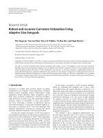
5. THE MULTIPASS STRATEGY
The multipass strategy that is explored in this paper is based
on the following idea. Once the (B
− T)N
t
data symbols for
Stefano Buzzi 7
Channel
estimator
Multiuser
detector
r(p)
q(.)
Detected bits
Figure 2: Block-scheme representation of the multipass strategy.
each user have been detected, they can be fed back, along
with the training bits, to the channel estimation algorithm
that can treat them as a fictitious training sequence of length
KN
t
B. Based on the knowledge of such fictitious training
symbols, a new channel estimate can be thus computed. Ob-
viously, intuition suggests that if the data symbols have been
detected with a sufficiently low error probability, the new
channel estimate will be much more reliable than the pre-
vious one, and, accordingly, feeding this channel estimate to
the data detector will provide an even lower data error prob-
ability. If, instead, the data symbols have been detected with
a large error probability, we expect that the new channel esti-
mate will be worse than the previous one and an error prop-
agation process may arise. Luckily enough, both analytical
findings and numerical results, to be illustrated in the re-
mainder of the paper, will confirm the following two remark-
able features of the multipass strategy: (a) under many sce-
narios of relevant interest the proposed iterative approach is
convenient even when the data symbols are detected with an
error probability which is about 10
−1
; and (b) few iterations
(i.e., 2-3) between the data detector and the channel estima-
tor are sufficient to provide huge performance gains with re-
spect to the case that no multipass st rategy is employed. A
block scheme of the multipass estimator/detector is depicted
in Figure 2. Obviously, any channel estimation and data de-
tection algorithm illustrated in the previous section can be
used as building blocks of the scheme in the figure.
5.1. Performance analysis
Before illustrating some numerical results, we provide a the-
oretical analysis and derive an approximate closed-form for-
mula for the channel estimation mean square error (CEMSE)
at a given iteration of the multipass strategy.
To begin with, we first consider the initial stage of the
multipass strategy analyzing the CEMSE when only the
known TN
t
training bits are used for channel estimation.
Substituting (16) into (21), with T in place of n, and letting
Q
T
=
T
p
=1
F
H
p
F
p
, it is easily seen that
6
q(T) = q + Q
−1
T
T
p=1
F
H
p
w(p)
, (36)
6
Note that in this scenario, the considered least-squares estimator coin-
cides with the maximum-likelihood channel estimate.
whereby we can claim that the channel estimator q(T)is
unbiased and the corresponding CEMSE is given by
E
q(T) − q
2
=
2N
0
trace
Q
−1
T
. (37)
The CEMSE can be also given a more informative approxi-
mate expression. Indeed, since in a long-code CDMA system
the spreading codes are well modeled as realizations of a se-
quence of independent equally likely binary variates, substi-
tuting the time average of the matrices F
H
p
F
p
with a statis-
tical expectation, the following approximate formula for the
CEMSE at the initial stage of the multipass strategy can be
found:
E
q(T) − q
2
≈
2N
0
(N +1)MKN
t
N
r
NT
. (38)
It is thus seen that, as expected, the CEMSE is a decreas-
ing function of the number of signaling intervals devoted to
training.
Let us now consider the more interesting situation that
the entire frame of duration BT
b
is fed back to the channel
estimator. Equation (21)isnowwrittenas
q(B) =
B
p=1
F
H
p
F
p
−1
·
B
p=1
F
H
p
r(p)
, (39)
wherein the matrix
F
p
contains, for p>Tthe detected bits,
say
b
n
t
k
(p), in lieu of the true information symbols. Letting
Q
B
=
B
p=1
F
H
p
F
p
, and substituting (16) into (39), we have
q(B) = q +
Q
−1
B
B
p=1
F
H
p
F
p
− F
p
q + w(p)
. (40)
From the above equation, it is seen that the iterative strat-
egy makes the channel estimate no longer unbiased. In order
to come up with a closed-form formula for the CEMSE, we
make the assumption of considering the statistics of the de-
tected bits
b
n
t
k
(·) independent of the additive thermal noise,
and, also, approximate the computation of fourth-order mo-
ments in terms of products of second-order moments.
7
First
of all, we have to consider the term
E
B
p=1
F
p
−
F
p
H
F
p
=
E
B
p=T+1
F
p
−
F
p
H
F
p
. (41)
In order to give an informative expression to the right-hand
side of (41), we note that the matrix (A
k,p
−
A
k,p
)
H
A
k,p
can
be approximated as block diagonal; moreover, it can be also
shown that
C
n
t
H
k,p
C
n
t
k,p
≈ Diag
0, 1, , N − 1, N,N, N − 1, ,1,0
⊗ I
M
.
(42)
7
Note that this last assumption is quite customary in the analysis of adap-
tive algorithms. Moreover, numerical results will show that both these as-
sumptions have a negligible effect on the accuracy of the derived formulas.
8 EURASIP Journal on Wireless Communications and Networking
10
−3
10
−2
10
−1
10
0
p(e)
10
−1
10
0
10
1
10
2
CEMSE
Numerical simulation
Approximate formula
Lower bound (p(e) = 0)
No multipass strategy
Figure 3: CEMSE achieved by the channel estimator versus the er-
ror probability p(e) of the data detector at the previous iteration.
SNR
= 10 dB, N
t
= 2, N
r
= 2, K = 5, B = 400, T = 15, N = 15,
M
= 2.
Upon denoting by p(e) the bit error probability achieved by
the data detector at the previous iteration, we also have that
E
b
n
t
k
(p) −
b
n
t
k
(p)
b
n
t
k
(p)
=−
2p(e). (43)
Based on the above relations, some lengthy algebraic manip-
ulations, not reported here for the sake of brevity, lead to
E
B
p=T+1
F
p
−
F
p
H
F
p
≈
2p(e)(B − T)NI
(N+1)MKN
t
N
r
,
E
Q
−1
B
≈
1
BN
I
(N+1)MKN
t
N
r
.
(44)
Exploiting (44), it can be finally shown that the CEMSE
achieved by the channel estimator exploiting information
bits detected with a bit error probability p(e) can be finally
expressed as
E
q(B) − q
2
≈
4p(e)
2
(B − T)
2
B
2
q
2
+
2N
0
BN
K(N +1)MN
t
N
r
.
(45)
It is worth noting that relation (45) is extremely powerful,
in that it provides a simple expression of the CEMSE as a
function of the fundamental system parameters such as the
number of users, the processing gain, the number of transmit
and receive antennas, and, obviously, the error probability
achieved at the previous iteration. In Figure 3 we plot the ap-
proximate relation (45) versus the error probability p(e); for
comparison purposes, we also report the results of computer
simulations, as well as the CEMSE that would be achieved in
0 2 4 6 8 1012141618
SNR (dB)
10
−4
10
−3
10
−2
10
−1
10
0
Error probability
0th iteration
1st iteration
2nd iteration
3rd iteration
Ideal MMSE
Figure 4: Error probability for the linear MMSE receiver versus the
SNR. N
t
= 2, N
r
= 2, K = 5, B = 400, T = 15, N = 15, M = 2.
the case that all the information bits are detected w ith no er-
ror and the CEMSE (38) corresponding to the situation that
no multipass strategy is adopted. A Rayleigh-distributed 3-
path channel model has been considered; the considered sys-
tem parameters are reported in the caption of the figure. The
computer simulation results have been obtained by repeating
10
5
times the following procedure. First, N
t
B bits are ran-
domly generated and used to generate the discrete-time vec-
tors r(1), , r(B); then, random errors with probability p(e)
are introduced on the N
t
(B − T) information bits and, after
that, these errored bits are fed to the channel estimator, that
uses them, along with the N
t
T actual training bits, to per-
form the channel estimate; based on the output of the chan-
nel estimator the CEMSE can be computed. Interestingly, it is
seen that the experimental results are in excellent agreement
with the approximate relation (45). Moreover, on one hand,
it is seen that even large values of the error probability (close
to 0.5) lead to a reduction of the CEMSE. On the other hand,
results show that the case that p(e)
≤ 10
−2
(Note that such
values of the error probability may be obtained, even with an
initially large CEMSE, by properly increasing the signal-to-
noise ratio) permits achieving the same CEMSE that would
be achieved in the ideal situation that the whole transmitted
packet is known and exploited for channel estimation.
5.2. Numerical bit error rate results
The results of Figure 3 have shown that the performance
of the channel estimation scheme can have a large bene-
fit from the use of the multipass strategy; accordingly, it
is reasonably expected that the CEMSE reduction leads to
a considerable reduction in the bit error rate also. Indeed,
this intuition is confirmed by the results of some computer
Stefano Buzzi 9
0 2 4 6 8 1012141618
SNR (dB)
10
−4
10
−3
10
−2
10
−1
10
0
Error probability
0th iteration
1st iteration
2nd iteration
3rd iteration
Ideal MMSE
Figure 5: Error probability for the iterative MMSE receiver versus
the SNR. N
t
= 2, N
r
= 2, K = 5, B = 400, T = 15, N = 15, M = 2.
simulations. In Figures 4 and 5 we thus report the error
probability versus the signal-to-noise r atio for the linear
MMSE receiver (Section 4.1 ) and for the iterative MMSE re-
ceiver (Section 4.2). The considered system parameters are
reported in the caption of the figures. Again we consider a
Rayleigh-distributed 3-path channel model. The curves la-
beled as “0 iteration” correspond to the situation that no
multipass strategy has been employed, while the remain-
ing curves show the error probability after some iterations.
Moreover, for comparison purposes, we also report the er-
ror probability of the ideal linear MMSE receiver, which as-
sumes perfect knowledge of the channel vectors. It is clearly
seen that the multipass strategy permits achieving a perfor-
mance gain of about 10 dB, and, as regards linear MMSE
detection, performs pretty close to the ideal MMSE receiver
which has a perfect knowledge of the channel. As expected,
it is seen that the iterative MMSE receiver p erformance is
worse than that of the linear MMSE receiver, but, however,
also for the iterative receiver the multipass strategy leads to
a remarkable performance improvement. The results of Fig-
ures 4 and 5 refer to the situation that each user is assigned N
t
different spreading codes, that is, one for each transmit an-
tenna. However, the proposed channel estimation and data
detection scheme does work also when just one spreading
code is assigned to each user, and is used to spread the in-
formation symbols on all the transmit antennas. In Figures 6
and 7 we thus report the performance of the linear MMSE
receiver (Section 4.1) and of the iterative MMSE receiver
(Section 4.2), respectively, in the “same signatures” scenario.
It is seen that the performance is practically coincident with
the one reported in Figures 4 and 5. This is a remarkable
feature of the proposed strategy. Indeed, the use of different
0 2 4 6 8 1012141618
SNR (dB)
10
−4
10
−3
10
−2
10
−1
10
0
Error probability
0th iteration
1st iteration
2nd iteration
3rd iteration
Ideal MMSE
Figure 6: Error probability for the linear MMSE receiver versus the
SNR. Each user is assigned one signature waveform, which is thus
used to spread data symbols on all its transmit antennas. N
t
= 2,
N
r
= 2, K = 5, B = 400, T = 15.
spreading codes may lead to a spreading code shortage and,
eventually, to a drastic reduction in the number of users, thus
implying that the ability to use just one spreading code per
user in multiantenna systems is a fundamental requisite.
Overall, results show that the multipass strategy is an ef-
fective strategy to achieve excellent performance levels with
very short training sequences. Otherwise stated, the multi-
pass strategy retains the advantages of both trained and blind
systems, that is, excellent performance levels and close-to-
one throughput.
5.3. Setting of the optimal training length
A general question in the design of wireless communication
systems is how to set the amount of time devoted to training.
In principle, the length of the training phase is to be chosen
as a compromise between the conflicting requirements of
achieving a reliable channel estimate and of not reducing
too much the system throughput. As a consequence, a possi-
ble reasonable optimization strategy is to choose the training
length T as the one that minimizes the following objective
function:
γ(T)
=
E
q(·) − q
2
(B − T)/B
(46)
which is the CEMSE-to-throughput ratio. Based on the ap-
proximate expressions (38)and(45), it is easily seen that the
objective function γ(T) is expressed as
γ(T)
= 2N
0
B(N +1)MKN
t
N
r
NT(B − T)
, (47)
10 EURASIP Journal on Wireless Communications and Networking
0 2 4 6 8 1012141618
SNR (dB)
10
−4
10
−3
10
−2
10
−1
10
0
Error probability
0th iteration
1st iteration
2nd iteration
3rd iteration
Ideal MMSE
Figure 7: Error probability for the iterative MMSE receiver versus
the SNR. Each user is assigned one signature waveform, which is
thus used to spread data symbols on all its transmit antennas. N
t
=
2, N
r
= 2, K = 5, B = 400, T = 15.
for the case that the multipass strategy is not implemented,
and
γ(T)
= 4p(e)
2
B − T
B
q
2
+
2N
0
(B − T)N
K(N +1)MN
t
N
r
,
(48)
when the multipass strategy is adopted. Through elementary
calculus it is seen that (47) is minimum for T
= B/2, that is,
when no multipass strategy is adopted half of the time should
be spent in training. As to (48), unfortunately its minimiza-
tion is not trivial, since the error probability p(e) depends in
a complicated way on the training length T.Inorder,how-
ever, to be able to assess the impact of the multipass strateg y
on the objective function γ(T), in Figure 8(a) we report the
minimum (with respect to the training sequence length T)of
γ(T) versus the error probability p(e), for both the cases that
the multipass strategy is adopted and that the multipass strat-
egy is not adopted. In this latter situation, obviously, the min-
imum of γ(T) is independent of p(e) and is thus represented
by a straight horizontal line in the figure. In Figure 8(b), in-
stead, the minimizer of γ(T)isrepresentedversusp(e), for
the multipass and the conventional strategy. Also in this case
the considered system para meters are reported in the figures
caption. Interestingly, it is seen that, in the considered sce-
nario, it suffices to have p(e)
≤ 4 · 10
−2
for the multipass
strategy to outperform the conventional strategy (note that
such small values for the error probability can be achieved,
for small training lengths, by properly increasing the signal-
to-noise ratio). In particular, it is thus seen that in the re-
gion of interest of low error probabilities the multipass strat-
egy permits achieving a smaller value of the cost function
γ(T). Moreover, and mostly important, it is seen from the
lower plot that for moderately low error probabilities the op-
timal training sequence length coincides with its minimum
value (see (20)), thus implying that, as already pointed out,
the system achieves at the same time a throughput close to
that of blind systems and a performance close to that of sys-
tems adopting long training sequences. The experimental re-
sults thus confirm again the huge performance gains that are
granted by the use of this recursive approach.
5.4. Multiple antennas versus single-antenna systems
As already commented, it is well known that multiple-
antenna systems are capable of achie ving much better per-
formance than single-antenna systems. It should be however
noted that most studies available in the literature compare
single-antenna and multiple-antenna systems under the as-
sumption that perfect channel knowledge is available at the
receiver. In practice, however, the channel realizations are to
be estimated at the receiver, and, since the task of channel
estimation is much more challenging for multiple-antenna
systems, the question thus arises to understand whether
multiple-antenna systems are still so advantageous when no
channel state information is assumed. This issue has been re-
cently tackled in the literature (see for instance [19, 20]), and
it has been shown that, even if channel estimation is explicitly
accounted for, using multiple-antenna systems brings per-
formance improvements with respect to the use of a single-
antenna system. A thorough theoretical discussion of this is-
sue is well beyond the scope of this paper. However, in the
following we present some simulation results that compare
a single-antenna system with multiple-antenna systems. In
particular, putting a constraint on the available bandwidth
and on the data rate of the information stream to be con-
veyed, we have compared a single-antenna system employ-
ing 8 PSK modulation with a multiple-antenna system with
N
t
= 3, N
r
= 1, and with N
t
= N
r
= 2, and w ith BPSK mod-
ulation. The results are shown in Figure 9, wherein the per-
formance of the ideal MMSE receiver (i.e., assuming a known
channel) for the 8 PSK single-antenna system is reported ver-
sus the performance of the proposed multipass strategy for
the systems with N
t
= 3, N
r
= 1, and with N
t
= N
r
= 3.
While the system with just one receive antenna performs
slightly worse than the 8 PSK single-antenna system, it is seen
that, despite the challenge of estimating 6 different channels
for each user, the system equipped with 3 antennas at the
transmitter and 2 at the receiver well outperforms by many
dBs the single-antenna system. Other simulations, whose re-
sults are not reported here for the sake of brevity, have shown
that such a performance gain is even larger when the number
of receive antennas is increased. In agreement with the find-
ings of [19, 20], it is thus experimentally show n that the use
of multiple antennas is beneficial despite the increased num-
ber of channel impulse responses that are to be estimated.
6. SPACE-TIME CODED CDMA SYSTEMS
In this section we show how the proposed iterative strategy
can be extended to space-time coded systems. In particular,
Stefano Buzzi 11
10
−3
10
−2
10
−1
p(e)
10
−1
10
0
min
T
γ(T)
Multipass strategy
No multipass strategy
(a)
10
−3
10
−2
10
−1
p(e)
0
50
100
150
200
250
300
arg min
T
γ(T)
Multipass strategy
No multipass strategy
(b)
Figure 8: (a) Minimum of γ(T)versusp(e) for the multipass and conventional strateg y. (b) Minimizer of γ(T)versusp(e) for the multipass
and conventional strategy. It is seen that, for reasonable values of p(e), the multipass strategy achieves lower values of the cost-function γ(
·)
and, also, a larger throughput. SNR
= 6dB,N
t
= 2, N
r
= 2, K = 4, B = 300, N = 15, M = 2.
0 2 4 6 8 10 12 14 16 18
SNR (dB)
10
−4
10
−3
10
−2
10
−1
10
0
Bit error probability
Ideal MMSE, single antenna, 8PSK
N
r
= 1, N
t
= 3, 0th iteration, BPSK
N
r
= 1, N
t
= 3, 1st iteration, BPSK
N
r
= 1, N
t
= 3, 3rd iteration, BPSK
N
r
= 2, N
t
= 3, 0th iteration, BPSK
N
r
= 2, N
t
= 3, 1st iteration, BPSK
N
r
= 2, N
t
= 3, 3rd iteration, BPSK
Figure 9: Er ror probability for a single-antenna system with 8 PSK
modulation versus BPSK multiple-antenna systems with N
t
= 3and
N
r
= 1, 3. Linear MMSE Receiver, K = 4, B = 200, T = 20.
we focus on the popular Alamouti space-time coding scheme
[17]; note, however, that our approach can be extended with
moderate efforts to any orthogonal space-time code. In its
basic configuration, the Alamouti scheme requires N
t
= 2
transmit antennas and N
r
= 1 receive antenna. Denoting
by
···b
k
(p)b
k
(p +1)b
k
(p +2)··· the information stream
of the kth user, in the (2p)th signaling interval, the symbols
b
k
(2p)andb
k
(2p + 1) are sent by the first and second trans-
mit antennas of the kth user, respectively, while, in the subse-
quent (2p + 1)th signaling interval, the symbols
−b
∗
k
(2p +1)
and
−b
∗
k
(2p) are transmitted, each on a separate antenna
(see also [17] for further details). As regards the issue of
channel estimation, the structure impressed by the Alamouti
scheme on the transmitted symbols has no e ffect on the pre-
viously outlined channel estimation procedure, whereby we
just dwell on the issue of data decoding. It is easily shown that
the discrete-time signal observed in the interval I
2p
is given
by the 2NM-dimensional vector
r
2
(2p) =
K−1
k=0
−
b
∗
k
(2p − 1)
D
l,1
k,2p
−1
+ b
k
(2p)D
1
k,2p
− b
∗
k
(2p +1)
D
u,1
k,2p+1
g
1
k
+
b
∗
k
(2p − 2)
D
l,2
k,2p
−1
+ b
k
(2p +1)D
2
k,2p
+ b
∗
k
(2p)
D
u,2
k,2p+1
g
2
k
+ w
2
(2p),
(49)
while the vector r
2
(2p + 1), observed in the interval I
2p+1
,is
written as
r
2
(2p +1)=
K−1
k=0
b
k
(2p)
D
l,1
k,2p
− b
∗
k
(2p +1)D
1
k,2p+1
+ b
∗
k
(2p +2)
D
u,1
k,2p+2
g
1
k
+
b
∗
k
(2p +1)
D
l,2
k,2p
+ b
∗
k
(2p)D
2
k,2p+1
+ b
k
(2p +3)
D
u,2
k,2p+2
g
2
k
+ w
2
(2p +1).
(50)
Consider now the 4NM-dimensional data vector y(p)
=
[
r
T
2
(2p) r
H
2
(2p +1)
]. Since we have assumed that the infor-
mation symbols are real, it is easily shown that the vector
12 EURASIP Journal on Wireless Communications and Networking
y(p)canbewrittenas
y(p)
=
K−1
k=0
b
k
(2p − 2)
⎡
⎣
D
l,2
k,2p
−1
g
2
k
0
⎤
⎦
−
b
k
(2p − 1)
⎡
⎣
D
l,1
k,2p
−1
g
1
k
0
⎤
⎦
+ b
k
(2p)
⎡
⎢
⎣
D
1
k,2p
g
1
k
+
D
u,2
k,2p+1
g
2
k
D
l,1
k,2p
g
1
k
+ D
2
k,2p+1
g
2
k
∗
⎤
⎥
⎦
−
b
k
(2p +1)
⎡
⎢
⎣
D
u,1
k,2p+1
g
1
k
− D
2
k,2p
g
2
k
D
1
k,2p+1
g
1
k
− D
l,2
k,2p
g
2
k
∗
⎤
⎥
⎦
+ b
k
(2p +2)
⎡
⎣
0
D
u,1
k,2p+2
g
1
k
⎤
⎦
∗
+ b
k
(2p +3)
⎡
⎣
0
D
u,2
k,2p+2
g
2
k
⎤
⎦
∗
+
⎡
⎣
w
2
(2p)
w
2
(2p +1)
∗
⎤
⎦
.
(51)
Now, note that the above equation (51)hasastructurewhich
is similar to that of (27). As a consequence, the same steps
that have led to the previous derivation of the MIMO mul-
tiuser detectors processing (27)canbefollowedinorder
to obtain MIMO multiuser receivers that process the data
(27) in order to provide estimates of the symbols b
k
(2p)
and b
k
(2p +1)forallk = 0, , K − 1. Due to lack of
space, we do not provide here more details, and just report
some simulation results showing that the multipass strategy
is very effective also for space-time coded multiuser systems.
In Figure 10 we show the error probability of the MMSE re-
ceiver in the situation that the Alamouti space-time code and
the multipass strategy are employed. The considered system
parameters are reported in the figure’s caption. It is seen that
also in this case the multipass strategy achieves a huge perfor-
mance gain in just one iteration, while, after three iterations
andatanerrorprobabilityof10
−4
, the system is less than
1 dB far from the ideal MMSE receiver that assumes perfect
knowledge of the channel vectors.
7. CONCLUSIONS
In this paper the issue of joint channel estimation and mul-
tiuser detection for long-code MIMO DS/CDMA systems
operating on frequency-selective channels has been consid-
ered. Extending the results reported in [9]withregardto
a single-antenna system, we have proposed to use a multi-
pass strategy wherein the channel estimator and the data de-
tector recursively exchange information in order to improve
the system performance. It is seen that this simple str ategy
yields huge and impressive performance gains even when the
training length is very small. In particular, we have shown,
through both theoretical considerations and simulation re-
sults, that the proposed multipass strategy achieves a reduc-
tion in the CEMSE, in the system error probability, and in the
0 2 4 6 810 121416 18
SNR (dB)
10
−4
10
−3
10
−2
10
−1
10
0
Error probability
0th iteration
1st iteration
2nd iteration
3rd iteration
Ideal MMSE
Figure 10: Error probability for the linear MMSE receiver ver-
sus the SNR. Alamouti space-time coded system. A Rayleigh-
distributed 3-path channel model has been considered. The pro-
cessing gain N is 15 and the oversampling factor M is 2. N
t
= 2,
N
r
= 1, K = 6, B = 200, T = 20.
optimal length of the training phase. It is worth pointing out
that the multipass strategy has a general validity, and can be
applied to improve performance in many wireless commu-
nication systems. As an example, the proposed strategy can
be used also to per form timing and frequency synchroniza-
tion. An interesting generalization of the multipass strategy is
also the consideration of convolutionally coded systems. In-
deed, it is expected that designing ad hoc iterative st rategies
wherein the data detector, the code decoder, and the channel
estimator exchange soft information in a turbo-like fashion
may lead to very remarkable performance gains. These issues
form the object of current research.
REFERENCES
[1]E.Dahlman,P.Beming,J.Knutsson,F.Ovesjo,M.Persson,
and C. Roobol, “WCDMA-the radio interface for future mo-
bile multimedia communications,” IEEE Transactions on Ve-
hicular Technology, vol. 47, no. 4, pp. 1105–1118, 1998.
[2] U. Madhow, “Blind adaptive interference suppression for
direct-sequence CDMA,” Proceedings of the IEEE, vol. 86,
no. 10, pp. 2049–2069, 1998.
[3] X. Wang and H. V. Poor, “Blind multiuser detection: a sub-
space approach,” IEEE Transactions on Information Theory,
vol. 44, no. 2, pp. 677–690, 1998.
[4] A. J. Weiss and B. Friedlander, “Channel estimation for
DS-CDMA downlink w ith aperiodic spreading codes,” IEEE
Transactions on Communications, vol. 47, no. 10, pp. 1561–
1569, 1999.
[5] Z. D. Xu and M. K. Tsatsanis, “Blind channel estimation for
long code multiuser CDMA systems,” IEEE Transactions on
Signal Processing, vol. 48, no. 4, pp. 988–1001, 2000.
Stefano Buzzi 13
[6] C. J. Escudero, U. Mitra, and D. T. M. Slock, “A Toeplitz dis-
placement method for blind multipath estimation for long
code DS/CDMA signals,” IEEE Transactions on Signal Process-
ing, vol. 49, no. 3, pp. 654–665, 2001.
[7] V. Tripathi, A. Mantravadi, and V. V. Veeravalli, “Channel ac-
quisition for wideband CDMA signals,” IEEE Journal on Se-
lected Areas in Communications, vol. 18, no. 8, pp. 1483–1494,
2000, Special issue on Wideband CDMA.
[8] S. Buzzi and H. V. Poor, “Channel estimation and multiuser
detection in long-code DS/CDMA systems,” IEEE Journal on
Selected Areas in Communications, vol. 19, no. 8, pp. 1476–
1487, 2001.
[9] S. Buzzi and H. V. Poor, “A multipass approach to joint data
and channel estimation in long-code CDMA systems,” IEEE
Transactions on Wireless Communications,vol.3,no.2,pp.
612–626, 2004.
[10] I. E. Telatar, “Capacity of multi-antenna Gaussian channels,”
European Transactions on Telecommunications, vol. 10, no. 6,
pp. 585–595, 1999.
[11] G. J. Foschini and M. J. Gans, “On limits of wireless commu-
nications in a fading environment when using multiple an-
tennas,” Wireless Personal Communications,vol.6,no.3,pp.
311–335, 1998.
[12] T. L. Marzetta and B. M. Hochwald, “Capacity of a mobile
multiple-antenna communication link in Rayleigh flat fading,”
IEEE Transactions on Information Theory,vol.45,no.1,pp.
139–157, 1999.
[13] G. J. Foschini, “Layered space-time architecture for wireless
communication in a fading environment when using multi-
element antennas,” Bell Labs Technical Journal,vol.1,no.2,
pp. 41–59, 1996.
[14] G. J. Foschini, G. D. Golden, R. A. Valenzuela, and P. W. Wolni-
ansky, “Simplified processing for high spectral efficiency wire-
less communication employing multi-element arrays,” IEEE
Journal on Selected Areas in Communications, vol. 17, no. 11,
pp. 1841–1852, 1999.
[15] B. M. Hochwald, T. L. Marzetta, and C. B. Papadias, “A trans-
mitter diversity scheme for wideband CDMA systems based
on space-time spreading,” IEEE Journal on Selected Areas in
Communications, vol. 19, no. 1, pp. 48–60, 2001.
[16] D. Reynolds, X. Wang, and H. V. Poor, “Blind adaptive
space-time multiuser detection with multiple transmitter and
receiver antennas,” IEEE Transactions on Signal Processing,
vol. 50, no. 6, pp. 1261–1276, 2002.
[17] S. M. Alamouti, “A simple transmit diversity technique for
wireless communications,” IEEE Journal on Selected Areas in
Communications, vol. 16, no. 8, pp. 1451–1458, 1998.
[18] G. H. Golub and C. F. Van Loan, Matrix Computations,The
Johns Hopkins University Press, Baltimore, Md, USA, 3rd edi-
tion, 1996.
[19] L. Mailaender, “Capacity bound for linear MIMO systems
with channel estimation,” in Proceedings of IEEE 6th Work-
shop on Sig nal Processing Advances in Wireless Communications
(SPAWC ’05), pp. 1048–1052, New York, NY, USA, June 2005.
[20] T. Yoo and A. Goldsmith, “Capacity of fading MIMO channels
with channel estimation error,” in Proceedings of IEEE Inter-
national Conference on Communications (ICC ’04), vol. 2, pp.
808–813, Paris, France, June 2004.
Stefano Buzzi was born in Piano di Sor-
rento, Italy, on December 10, 1970. He re-
ceived with honors the Dr. Eng. deg ree in
1994, and the Ph.D. degree in electronic
engineering and computer science in 1999,
both from the University of Naples “Fed-
erico II.” In 1996 he spent six months
at Centro Studi e Laboratori Telecomuni-
cazioni (CSELT), Turin, Italy, while from
November 1999 through December 2001 he
has spent eight months at the Department of Electrical Engineer-
ing, Princeton University, as a Visiting Research Fellow. He is cur-
rently an Associate Professor at the University of Cassino, Italy.
His current research and study interests lie in the area of sta-
tistical signal processing, with emphasis on signal detection in
non-Gaussian noise and multiple-access communications. He was
awarded by the AEI (Associazione Elettrotecnica ed Elettronica
Italiana) the “G. Oglietti” scholarship in 1996, and was the recipient
of a NATO/CNR advanced fellowship in 1999 and of a CNR short-
term mobility grant in 2000 and 2001. He is currently serving as
an Associate Editor for the IEEE Signal Processing Letters, the IEEE
Communications Letters, and the Journal of Communications and
Networks.