Báo cáo hóa học: " Design and Characterization of a 5.2 GHz/2.4 GHz ΣΔ Fractional-N Frequency Synthesizer for Low-Phase Noise Performance" potx
Bạn đang xem bản rút gọn của tài liệu. Xem và tải ngay bản đầy đủ của tài liệu tại đây (1.13 MB, 11 trang )
Hindawi Publishing Corporation
EURASIP Journal on Wireless Communications and Networking
Volume 2006, Article ID 48489, Pages 1–11
DOI 10.1155/WCN/2006/48489
Design and Characterization of a 5.2 GHz/2.4 GHz ΣΔ
Fractional-N Frequency Synthesizer for Low-Phase
Noise Per formance
John W. M. Rogers,
1
Foster F. Dai,
2
Calvin Plett,
1
and Mark S. Cavin
3
1
Carleton University, 1125 Colonel Drive Ottawa, ON, Canada K1S 5B6
2
Electrical and Computer Engineering Department, Auburn University, Auburn, AL 36849-5201, USA
3
Alereon, Inc., 7600 North Capital of Texas Highway, Building C, Suite 200 Austin, TX 78731, USA
Received 8 August 2005; Revised 8 January 2006; Accepted 13 January 2006
This paper presents a complete noise analysis of a ΣΔ-based fractional-N phase-locked loop (PLL) based frequency synthesizer.
Rigorous analytical and empirical formulas have been given to model various phase noise sources and spurious components and
to predict their impact on the overall synthesizer noise performance. These formulas have been applied to an integrated multiband
WLAN frequency synthesizer RFIC to demonstrate noise minimization through judicious choice of loop parameters. Finally,
predicted and measured phase jitter showed good agreement. For an LO frequency of 4.3 GHz, predicted and measured phase
noise was 0.50
◦
rms and 0.535
◦
rms, respectively.
Copyright © 2006 John W. M. Rogers et al. This is an open access article distributed under the Creative Commons Attribution
License, which permits unrestricted use, distribution, and reproduction in any medium, provided the original work is properly
cited.
1. INTRODUCTION
High-speed frequency synthesis is one of the most challeng-
ing areas in radio frequency integrated circuit (RFIC) design.
It requires diverse knowledge of both high-speed analog and
digital circuits as well as deep knowledge of system level is-
sues. The performance requirements on circuits used for fre-
quency synthesis are often extremely demanding making the
design of these blocks even more chal lenging. However, a
high-performance frequency synthesizer is a key component
in many wired (fiber or cable) and wireless communication
systems.
For modern multistandard applications, it is often diffi-
cult to cover multiple frequency bands using classical integer-
N frequency synthesizers whose step size is limited by the ref-
erence frequency. In order to achieve fine step size to cover
the multiband channel frequencies, one has to lower the ref-
erence frequency in an integer-N synthesizer design, which
results in high division ratio of the PLL and thus high in-
band phase noise. In contrast, a fractional-N synthesizer al-
lows the PLL to operate with a high reference frequency while
achieving fine step size by constantly swapping the loop di-
vision ratio between integer numbers, thus the average divi-
sion ratio is a fractional number [1–4]. However, fine step
size and low in-band phase noise is achieved with the penalty
of fractional spurious tones, which come from the period-
ical division ratio variation. To remove the fractional spu-
rious components for a synthesizer with fine step size, the
best solution is to employ a ΣΔ noise shaper to control a
programmable divider. A ΣΔ noise shaper will help to move
large spurs to higher frequencies where they can be easily fil-
tered. While spurs are often one of the most important de-
sign considerations for a frequency synthesizer, they will not
be treated in detail in this paper. Since these techniques are
becoming more and more common in modern synthesizer
design, noise in this style of synthesizer will b e the focus of
this paper.
Here, a theoretical analysis of phase noise in modern fre-
quency synthesizers will be presented. Phase noise is often
the most challenging and crucial performance specification
that must be met by a synthesizer. It is also the specification
that often proves the most difficult to model and simulate.
In this paper, a review of basic phase noise concepts will be
presented, followed by a model that will allow the designer to
take noise data from individual circuit simulations and pre-
dict the overall phase noise performance of an entire PLL fre-
quency synthesizer.
The proposed analytical model will then be used to pre-
dict and optimize the phase noise performance of a ΣΔ
fractional-N frequency synthesizer designed for multiband
2 EURASIP Journal on Wireless Communications and Networking
Ref
samp
log
10
dB/
−18 dBm Atten 10 dB
LgAv
100
W
1
S
3
S
2
FC
£( f ):
f>50 k
Swp
Center 1.056 01 GHz
ResBW91kHz VBW91kHz Sweep4.64 ms (601 pts)
Span 10 MHz
ΔMkr1 2.82 MHz
−73.961 dB
Carrier
signal
Discrete
spurs
Random
phase
noise
L
SSB
[dBc/Hz] =
P
c
[dBm/Hz]−P
n
[dBm/Hz]
P
n
P
c
1R
BW
= 1Hz
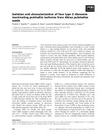
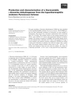
Figure 1: An example of phase noise and spurs at the synthesizer output observed using a spectrum analyzer.
WLAN applications. The comparison between the simulated
and the measured phase noise demonstrates that the analyti-
cal model can accurately predict the performance of the com-
plete synthesizer, and provide the designer with a quick and
reliable means to predict the phase noise performance of a
synthesizer RFIC prior to its fabrication.
2. BASIC PHASE NOISE CONCEPTS
Noise in synthesizers is contributed from all the building
block circuits a nd components that make up the PLL. Syn-
thesizer noise perfor mance is usually expressed as phase
noise, which is a measure of how much the output differs
from an ideal impulse function in the frequency domain. We
are primarily concerned with noise that causes fluctuations
in the phase of the output rather than noise that causes fluc-
tuations in the amplitude, since the output typically has a
fixed and limited amplitude. The output of a synthesizer can
be described as
v
out
(t) = V
o
sin
ω
LO
t + ϕ
n
(t)
,(1)
where ω
LO
t is the desired phase of the output and ϕ
n
(t)is
the time-variant random phase fluctuation of the output sig-
nal due to any noise sources in the PLL. Phase noise is often
quoted in units of dBc/Hz or rad
2
/Hz.
The phase fluctuation term ϕ
n
(t)in(1)mayberandom
phase noise or discrete spurious tones, also called spurs, as
shown in Figure 1. The discrete spurs at a synthesizer output
are most likely due to the fractional-N mechanism, while the
phase noise in an oscillator is mainly due to thermal, flicker,
or 1/f noise and the finite Q of the oscillator tank. Assume
the phase fluctuation is of a sinusoidal form as
ϕ(t)
= ϕ
p
sin
ω
m
t
,(2)
where ϕ
p
is the peak phase fluctuation and ω
m
is the offset
frequency from the carrier. Substituting (2) into (1)gives
v
out
(t) = V
0
cos
ω
c
t + ϕ
p
sin
ω
m
t
= V
0
cos
ω
c
t
cos
ϕ
p
sin
ω
m
t
− sin
ω
c
t
sin
ϕ
p
sin
ω
m
t
.
(3)
For a small phase fluctuation, the above e quation can be
simplified as
v
0
(t) = V
0
cos
ω
c
t
−
ϕ
p
sin
ω
m
t
sin
ω
c
t
=
V
0
cos
ω
c
t
−
ϕ
p
2
cos
ω
c
+ω
m
t−cos
ω
c
−ω
m
t
.
(4)
It is now evident that the phase-modulated signal in-
cludes the carrier signal tone and two symmetric sidebands
at any offset frequency, as shown in Figure 1. A spect rum an-
alyzer measures the phase noise power in dBm/Hz, but often
phase noise is reported relative to the carrier power as
PN(Δω)
=
Noise
ω
LO
+ Δω
P
carrier
ω
LO
,(5)
where Noise is the noise power in a 1 Hz bandwidth and
P
carrier
is the power of the carrier or local oscillator (LO)
tone at the frequency at which the synthesizer is operating.
In this form, phase noise has the units of [rad
2
/Hz]. Of-
ten this is quoted as so many dB down f rom the carrier in
units of [dBc/Hz]. To further complicate this, both single-
sideband and double-sideband phase noise can be defined.
Single-sideband (SSB) phase noise is defined as the ratio of
power in one phase modulation sideband per Hertz band-
width, at an offset Δω away from the carrier, to the total sig-
nal power. The SSB phase noise power spectral density (PSD)
John W. M. Rogers et al. 3
to carrier ratio, in units of [dBc/Hz], is defined as
PN
SSB
(Δω) = 10 log
N
ω
LO
+ Δω
P
carrier
ω
LO
. (6)
Combining (4) into (6) this equation can be rewritten as
PN
SSB
(Δω) = 10 log
(1/2)
V
0
ϕ
p
/2
2
(1/2)V
2
0
=
10 log
ϕ
2
p
4
=
10 log
ϕ
2
rms
2
,
(7)
where ϕ
2
rms
is the rms phase noise power density in units of
[rad
2
/Hz]. Note that single-sideband phase noise is by far the
most common type reported and often it is not specified as
SSB, but rather simply reported as phase noise. However, al-
ternatively double-sideband phase noise can be expressed by
PN
DSB
(Δω) = 10 log
N
ω
LO
+ Δω
+ N
ω
LO
− Δω
P
carrier
ω
LO
=
10 log
ϕ
2
rms
.
(8)
From either the single-sideband or double-sideband
phase noise, the rms phase noise can be obtained in the linear
domain as
ϕ
rms
(Δω) =
180
π
10
PN
DSB
(Δω)/10
=
180
√
2
π
10
PN
SSB
(Δω)/10
deg/
√
Hz
.
(9)
It is also quite common to quote integrated phase noise
over a certain bandwidth. The rms-integrated phase noise of
a synthesizer is given by
IntPN
rms
=
Δω
2
Δω
1
ϕ
2
rms
(ω)dω. (10)
The limits of integration are usually the offsets cor-
responding to the lower and upper frequencies of the
bandwidth of the information being transmitted.
In addition, it should be noted that dividing or multiply-
ing a sig nal in the time domain also divides or multiplies the
phase noise. Similarly, if a signal is translated in frequency by
afactorofN, then the phase noise power is increased by a
factor of N
2
as
ϕ
2
rms
Nω
LO
+ Δω
=
N
2
· ϕ
2
rms
ω
LO
+ Δω
,
ϕ
2
rms
ω
LO
N
+ Δω
=
ϕ
2
rms
ω
LO
+ Δω
N
2
.
(11)
Note this assumes that the circuit that did the frequency
translation is noiseless. Otherwise, additional phase noise
will be added. Also, note that the phase noise is scaled by N
2
rather than N because we are dealing with noise in units of
power rather than units of voltage.
3. BUILDING BLOCK PHASE NOISE MODELS
FOR PLL SYNTHESIZER
Next, we will present the phase noise models for all PLL
synthesizer building blocks such as the crystal oscillator, di-
vider, phase-frequency detector (PFD), charge pump (CP),
loop lowpass filter (LPF), and voltage-controlled oscillator
(VCO). While the circuit-or block-level simulation of a typi-
cal synthesizer desig n will not be discussed in detail in this
paper, some basic theory will be presented to show how
the noise in each block can affect the loop performance. In
Section 4, the effect of these noise sources on a complete syn-
thesizer will b e examined.
3.1. VCO noise
The phase noise from a VCO can be described as [5, 6]
ϕ
2
VCO
(Δω) =
ω
o
(2QΔω)
2
GkT
2P
S
1+
ω
c
Δω
, (12)
where P
S
is the signal power of the carrier, T is the tempera-
ture, Q is the quality factor of the oscillator’s resonator, k is
Boltzmann’s constant, ω
o
is the frequency of oscil lation, ω
c
is the flicker noise corner frequency, and G is a constant of
proportionality which takes into account excess noise from
the VCO transistors, and nonlinearity. Note that many ad-
ditional refinements have been made to this formula, how-
ever as given here it is sufficient to capture the shape of
most integrated VCO’s phase noise. Thus, at most frequen-
cies of interest, the phase noise produced by the VCO will
decrease at 20 dB/decade for an increasing offset frequency
away from the carrier. This will not continue indefinitely, as
thermal noise will put a lower limit on this phase noise which
for most integrated VCOs is somewhere between
−120 and
−150 dBc/Hz. VCO phase noise is usually dominant outside
the loop bandwidth and of less importance at low offset fre-
quencies.
3.2. Crystal reference noise
Crystal resonators are widely used in frequency control ap-
plications because of their unequaled combination of high Q,
stability, and small size. The resonators are classified accord-
ing to “cut,” which is the orientation of the crystal wafer (usu-
ally made from quartz) with respect to the crystallographic
axes of the material. The total noise power spectral density of
a crystal oscillator can also be found from Leeson’s formula
and making use of a typical empirical multiplier [7]:
ϕ
2
XTAL
(Δω) = 10
−16±1
·
1+
ω
0
2Δω · Q
L
2
1+
ω
c
Δω
,
(13)
where ω
0
is the oscillator output frequency, ω
c
is the corner
frequency between 1/ f and thermal noise regions, which is
normally in the range 1–10 kHz, Q
L
is the loaded quality fac-
tor of the resonator. Since Q
L
for crystal resonator is very
large (normally in the order of 10
4
to 10
6
), the reference noise
4 EURASIP Journal on Wireless Communications and Networking
contributes only to the very close-in noise and it quickly
reaches thermal noise floor at offset frequency around ω
c
.
3.3. Frequency divider noise
Frequency div iders consist of switching logic circuits, which
are sensitive to the clock timing jitter. The jitter in the time
domain can be converted to phase noise in the frequency
domain. Time jitter or phase noise occurs when rising and
falling edges of digital dividers are superimposed with spuri-
ous signals such as Johnson and flicker noise in semiconduc-
tor materials. Ambient effects result in variation of the trig-
gering level due to temperature and humidity. Frequency di-
viders generate spurious noise especially for high-frequency
operation. Dividers do not generate signals, but rather simply
change their frequency. Kroupa provided an empirical for-
mula, which estimates the amount of phase noise that fre-
quency dividers add to a signal [8, 9]:
ϕ
2
Div
Added
(Δω)
≈
10
−14±1
+10
−27±1
ω
2
do
2π · Δω
+10
−16±1
+
10
−22±1
ω
do
2π
,
(14)
where ω
do
is the divider output frequency and Δω is the offset
frequency. Notice that the first term in (14) represents the
flicker noise and the second term gives the white thermal
noise floor. The third term is caused by timing jitter due to
coupling, ambient, and supply variations.
3.4. Phase detector noise
Phase detectors experience both flicker and thermal noise.
At large offsets, phase detectors generate a white phase noise
floor typically about
−160 dBc/Hz, which is thermal noise-
dominant. The noise power spectral density of phase detec-
tors is estimated empirically by [ 9]
ϕ
2
PD
(Δω) ≈
2π · 10
−14±1
Δω
+10
−16±1
. (15)
3.5. Charge pump noise
The noise of the charge pump can be characterized as an out-
put noise current and is usually given in pA/
√
Hz. Note that
at this point in the loop, current represents the phase. The
charge pump output current noise can be a strong function
of the reference frequency and width of the current pulses.
Therefore, for low-noise operation it is desirable to keep the
charge pump sink and source currents matched as well as
possible. This is because current sources only produce noise
when they are on. When an ideal loop is locked, the sink and
source current sources in a charge pump are turned off,re-
sulting in zero net current charge or discharge of the hold-
ing capacitor. However, nonidealities result in finite pulses
i
n LPF
R
C
2
v
n
=
√
4kTR
C
1
Figure 2: Loop filter with thermal noise added.
that will turn on the source and sink currents for about
the same amount of time. The closer reality matches the
ideal case, the less noise will be produced. Also, note that
as the offset frequency is decreased, 1/f noise will become
more important, causing the noise to increase. This noise
can often be the dominant noise source at low-frequency off-
sets. Charge pump noise can be simulated with proper tools
such as Cadence pss pnoise analysis. The results depend on
the design in question so no simple general analytical for-
mula will be given here, however, an example will be given
later.
3.6. Loop filter noise
Loop filters can be analyzed for noise in the frequency do-
main in a linear manner. The most common loop filter that
will be examined in this paper will now be analyzed. It con-
sists of two capacitors and one resistor. For offchip filters, the
loss experienced by capacitors is negligible. Thus, the loop
filter contains only one noise source, the thermal noise a s-
sociated with the resistor R. The loop filter with its associ-
ated noise source can be drawn as shown in Figure 2.Now
the noise voltage develops a current flowing through the se-
ries combination of C
1
, C
2
,andR (assuming that the CP and
VCO are both open circuits), which is given by
i
n LPF
=
1
R
·
v
n
s
s +
C
1
+ C
2
/C
1
C
2
R
≈
1
R
·
v
n
s
s +1/C
2
R
.
(16)
Thus, this noise current will have a highpass characteristic,
and therefore the loop will not produce any noise at DC and
this noise will increase until the highpass corner is reached,
after which it will be flat. Other filters can be analyzed in a
similar manner.
3.7. Phase noise due to ΣΔ converters
Fractional-N synthesizers often include ΣΔ modulators to
shift the spurious components to a higher-frequency band,
where the loop filter can filter randomized spurs. In a ΣΔ
fractional-N synthesizer, the average loop divisor value cor-
responds to the desired output frequency and the instan-
taneous divisor value is dithered around the correct value by
John W. M. Rogers et al. 5
−E
q2
(z)
+
+
−
n
n bit
1
1 − z
−1
A
3
1bit
z
−1
+
+
+
E
q3
(z)
C
3
(z)
(1
− z
−1
)
2
N
3
(z)
−E
q1
(z)
+
+
−
n
n bit
1
1 − z
−1
z
−1
(n +1)bit
A
2
1bit
E
q2
(z)
+
+
+
+
+
−
C
2
(z)
1
− z
−1
N
2
(z)
F(z)
+
+
−
n
n bit
1
1 − z
−1
z
−1
(n +1)bit
A
1
1bit
E
q1
(z)
+
+
+
+
+
−
N
1
(z) = C
1
(z)
++
+
+
+
F(z)+
(1
− z
−1
)
3
E
q3
+
+
Fractional
divisor
Integer
divisor
I(z)
Tot a l
divisor
N(z)
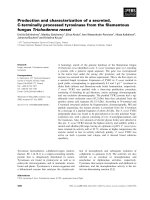
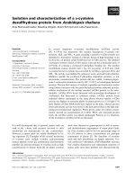
Figure 3: A three-loop MASH 1-1-1 ΣΔ modulator for fractional-N synthesis.
the ΣΔ modulator. The ΣΔ noise shaping can be modeled as
a linear gain stage with an additive quantization noise source,
which is shaped by a highpass transfer function. Hence, the
quantization error component at the synthesizer output is
composed of mostly high-frequency noise that can be fil-
tered by the PLL. A block diagram of a typical ΣΔ modulator
that is widely used in synthesizer applications is shown in
Figure 3 [3]. This three-loop sigma-delta topology is cal led
a MASH 1-1-1 structure, because it is a cascaded ΣΔ struc-
ture with three first-order loops. Each of the three loops is
identical. The input of the second loop is taken from the
quantized error E
q1
of the first loop, while the input of the
third loop is taken from the quantized error E
q2
of the second
loop. Thus, only the first loop has a constant input, which is
the fractional port ion of the desired rational divide number
F(z), that is, the fine tune word. The integer part of the fre-
quency word I(z), the coarse tune word, is added at the
output of the three-loop ΣΔ modulator. Thus, N
div
(z) =
I(z)+F(z) is the time sequence used to control the integer-
restricted divider ratios. The modulator is clocked at the di-
vider output frequency, reflecting the sampled nature of the
circuit.
The first loop generates the fractional divisor value F(z)
with the byproduct of quantization error E
q1
,whichisfur-
ther fed to the input of the second loop for further process-
ing. The second loop cancels the previous loop’s quantization
error E
q1
by the additional filter block (1 − z
−1
)initsoutput
path. The only quantization noise term left after summing
the first and second loop outputs is the quantization error
E
q2
, which is second-order noise-shaped. When this noise
term is further fed to the input of the third loop, the loop
generates a negative noise term to cancel the previous loop’s
quantization error E
q2
by the additional filter block (1−z
−1
)
2
in its output path. Summing the outputs of the three loops,
we obtain the modulated divisor value as
N(z)
= I(z)+N
1
(z)+N
2
(z)+N
3
(z)
= I(z)+F(z)+
1 − z
−1
3
E
q3
(z),
(17)
where I(z)andF(z) are the integer portion and the fractional
portion of the division ratio, respectively. As desired, the
fractional divisor value F(z)isnotaffected by the modula-
tor, while the quantization error generated in the last loop
E
q3
is noise-shaped by a third-order highpass function of
(1
− z
−1
)
3
. The quantization error generated in the first and
second loops are totally canceled, and as a result the total
quantization noise is equal to that of a single loop, although
three loops are used. Therefore, the multiloop sigma-delta
architecture provides high-order noise shaping without ad-
ditional quantization noise.
Discrete fractional spurs are generated by this circuit at
multiples of the reference frequency, but these spurs become
more like random noise after sigma-delta noise shaping. The
single-sideband phase noise of the noise-shaped fr actional
spurs can be analyzed as follows. The 1-bit quantization er-
ror power is Δ
2
/12 where Δ is the quantization step size. For
Δ
= 1, which is the case for a truncated binary word, the
quantization error power is 1/12. This error power is spread
over the sampling bandwidth, or equivalently the reference
bandwidth of f
r
= 1/T
s
. Thus, the error power spectral den-
sity (PSD) becomes 1/(12 f
r
). Considering the noise shap-
ing with an mth-order MASH ΣΔ modulator as expressed in
(17), the frequency noise PSD is obtained as
S
Ω
(z) =
1 − z
−1
m
f
r
2
12 f
r
=
1
12
1 − z
−1
2m
f
r
, (18)
6 EURASIP Journal on Wireless Communications and Networking
ϕ
noiseI
(s)
+
+
Crystal
reference
−
PFD
K
phase
UP
DN
Charge pump
I
CP
I
CP
Loop filter
VCO
+
ϕ
noiseII
(s)
ϕ
noise out
(s)
K
VCO
s
C
1
C
2
R
F(s)
+
÷N
ΣΔ
ϕ
ΣΔ
(s)
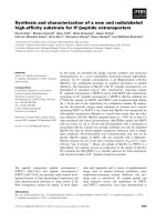
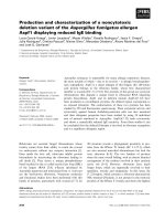
Figure 4: A synthesizer showing places where noise is injected.
where the subscript Ω denotes the frequency fluctuations re-
ferred to the input of the divider. In order to obtain the phase
fluctuations, consider the following relationship between fre-
quency and phase:
ω(t)
=
dφ(t)
dt
≈
φ(t) − φ
t − T
s
T
s
(19)
and its z-domain representation of
2π
· Ω(z) =
Φ(z)
1 − z
−1
T
S
, (20)
where T
s
= 1/f
r
is the sample period and where multiplica-
tion by z
−1
represents a delay of T
s
. Rearranging this expres-
sion yields
Φ(z)
=
2π · Ω(z)
f
r
1 − z
−1
. (21)
Noting that S
Ω
(z) is given in terms of power, the double-
sideband phase noise PSD is obtained as
S
Φ
(z) = S
Ω
(z)
(2π)
2
1 − z
−1
2
f
2
r
=
(2π)
2
1 − z
−1
2
f
2
r
·
1
12
1 − z
−1
2m
f
r
=
(2π)
2
12 f
r
·
1 − z
−1
2m−2
,
(22)
where the subscript Φ denotes phase fluctuations. Noting
that
1 − z
−1
=
1 − e
−jωT
=
2sin
ωT
2
=
2sin
πf
f
r
,
(23)
the single-sideband phase noise PSD in the frequency
domain is given by
ϕ
2
ΣΔ
( f )
rad
2
/Hz
2
=
(2π)
2
24 f
r
·
2sin
πf
f
r
2(m−1)
,
PN( f )[dBc/Hz]
= 10 log
(2π)
2
24 f
r
·
2sin
πf
f
r
2(m−1)
.
(24)
4. IN-BAND AND OUT-OF-BAND PHASE NOISE
IN PLL SYNTHESIS
A typical PLL-based synthesizer system level diagram that
will be analyzed in this paper is shown in Figure 4.Itcon-
sists of a phase-frequency detector, a charge pump, a loop
filter, a VCO, a programmable divider, a reference oscillator
(typically a crystal reference source), and a fractional accu-
mulator with ΣΔ modulation circuit to achieve the fine syn-
thesizer step size without impact ing the phase noise perfor-
mance.
The noise transfer functions for the var ious noise sources
in the loop can be derived using conventional control the-
ory [9, 10]. There are three additive noise transfer functions:
one for the VCO noise, that is, the contributor of the synthe-
sizer out-of-band noise, one for the ΣΔ modulator noise that
could contribute to both in-band and out-of-band noise, and
one for all other noise sources such as the PFD, CP, divider,
and loop filter that are the contributors of the in-band noise.
All in-band noise sources are referred back to the input of
the PLL and shown as ϕ
noiseI
in Figure 4. The noise from the
VCO is referred to the output and represented by ϕ
noiseII
in
Figure 4, while the noise from the ΣΔ modulator is shown
as ϕ
ΣΔ
. The noise transfer function (NTF) for in-band noise
ϕ
noiseI
(s)isgivenby
ϕ
noise out
(s)
ϕ
noiseI
(s)
=
IK
VCO
/2π · C
1
1+RC
1
s
s
2
+
IK
VCO
/2π · N
Rs + IK
VCO
/2π · NC
1
.
(25)
John W. M. Rogers et al. 7
As shown, the in-band noise transfer func tion has a
lowpass characteristic. Note that for low-frequencies inside
the loop bandwidth, the loop will track the input phase in-
cluding the input phase noise. Therefore, this noise will be
transferred to the PLL output. At higher offset frequencies,
this noise is suppressed by the loop’s lowpass filter. Thus, the
noise coming from the PFD, CP, divider, and loop filter con-
tributes to the in-band noise at the PLL output. Also, note
that the division ratio plays a very important role in this
transfer function. Within the loop bandwidth, the in-band
phase noise is magnified N times by the loop. T herefore,
choosing smaller divisor value N will benefit the in-band
noise reduction.
The VCO noise transfer function is slightly different. In
this case, setting the input reference and input noise source
to zero, the VCO noise transfer function is given by
ϕ
noise out
(s)
ϕ
noiseII
(s) =
s
2
s
2
+
IK
VCO
/2π · N
Rs + IK
VCO
/2π · NC
1
.
(26)
As shown, the VCO noise transfer function has a high-
pass characteristic. Thus, at low offsets inside the loop band-
width the VCO noise is suppressed by the feedback loop, yet
outside the loop bandwidth the VCO is essentially free run-
ning without noise attenuation. Thus, the out-of-band PLL
noise approaches the VCO noise.
The noise transfer function of the ΣΔ modulator is very
similar to the in-band noise transfer function except an extra
1/N term in the numerator a s the ΣΔ is not input-referred.
Note that due to the highpass nature of the ΣΔ NTF, the or-
der of the loop roll-off is very important. The noise shap-
ing slope of an mth-order MASH ΣΔ modulation is 20(m
−
1) dB/decade according to (24), while an nth-order lowpass
loop filter has a roll-off slope of 20n dB/decade. Therefore,
the order of loop filter must be higher than or equal to the
order of the ΣΔ modulator in order to attenuate the out-of-
band noise due to ΣΔ modulation. Thus, for instance, when
calculating the effec t of the ΣΔ modulator on out-of-band
noise on the ty pical loop, it is necessary to include additional
capacitor C
2
in the loop filter as this will provide extra atten-
uation out of band. In this case, the ΣΔ noise transfer func-
tion to the output would be
ϕ
noise out
(s)
ϕ
ΣΔ
(s)
=
K
VCO
K
phase
1+sC
1
R
s
2
N
C
1
+ C
2
1+sC
s
R
+ K
VCO
K
phase
1+sC
1
R
,
(27)
where C
s
= C
1
C
2
/(C
1
+ C
2
).
5. CIRCUIT-LEVEL PHASE NOISE COMPONENTS
The methods for dealing with phase noise wil l now be con-
sidered with application to an ac tual synthesizer RFIC design
case. T he results of the analysis can then be verified against
measurement data. The synthesizer to be considered was
designed using a 47 GHz 0.5 μm BiCMOS process using pri-
marily the CMOS part of the technology. The only exceptions
were some high-speed bipolar CML in the divider and the
output buffer circuits. The rest of the synthesizer including
the VCO cores was all CMOS. It was designed for multi-
band WLAN applications, and had a reference frequency of
40 MHz, a fairly standard charge pump and PFD configura-
tion with gain K
phase
of 750 μA/2π, a multimodulus div ider
programmable between 64 and 127, and an LC-based VCO
with a K
VCO
of approximately 120 MHz/V. The synthesizer
was designed to generate carrier frequencies in the range
from3.2to3.3GHzandfrom4.1to4.3GHz.TheMMD
gives a total division ratio of 86–88 and 102–108 under nor-
mal operating conditions and was controlled by a third-order
ΣΔ modulator to provide the needed step size and noise
shaping. The crystal oscillator used as a reference for this de-
sign had a Q
L
of 8 × 10
4
and a noise floor of −150 dBc/Hz.
The details of the actual circuit implementation will not be
discussed in this paper, but are similar to those given in [11].
The raw VCO phase noise can be either predicted from a
calculation [6] or else simulated with the aid of spectre or
some other simulator. Output current noise from the charge
pump/PFD combination can also be simulated or predicted
from transistor level noise calculations. This simulation must
be done using driving signals in the locked state to simu-
late accurately the amount of time the CP spends in the on
state. This simulation can be used to predict how much noise
current is on average produced by the circuit. Likewise sim-
ulations on the divider can be performed. The crystal oscil-
lator is normally a commercially available part and data on
its phase noise performance is often available from the man-
ufacturer. The ΣΔ phase noise can be estimated from (24).
Note that the maximum fractionality used in this design was
1/32. While this had an impact on the spurs of the system in
different channels, the third-order ΣΔ has kept all the spurs
below
−50 dBc level such that the fractional spurs did not af-
fect the phase noise of the system. Such simulations and cal-
culations were performed for the sample design. The results
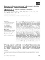
of all raw phase noise due to circuit components are plotted
in Figure 5. All phase noise is referred to the VCO output fre-
quency for easy comparison of the relative importance of the
phase noise sources.
Next the optimal loop bandwidth for best phase noise
performance must be determined. To do this the following
must be implemented.
(1) Plot all phase noise components.
(2) Determine the intercept point of ΣΔ and VCO noise.
(3) Compare it to the intercept between VCO noise and
in-band noise (normally dominated by charge pump
noise).
(4) If the ΣΔ intercepts the VCO noise at a lower fre-
quency than the in-band noise does, a higher-order
ΣΔ is needed to prevent in-band noise degradation.
Then make sure the higher-order ΣΔ noise intercepts
the VCO noise at a higher frequency than the in-band
noise does.
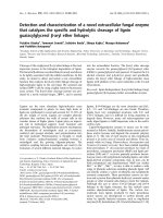
8 EURASIP Journal on Wireless Communications and Networking
10 00010001001010.1
Frequency (kHz)
−140
−130
−120
−110
−100
−90
−80
Phase noise (dBc/Hz)
(3) Crystal/CP intercept
Divider noise
Crystal noise
CP noise
(2) CP/VCO intercept
PD noise
(1) ΣΔ/VCO
intercept
VCO noise
ΣΔ noise
Figure 5: A plot of all raw phase noise components for the design
referred to the VCO output frequency.
(5) Choose the intercept between the out-of-band noise
(VCO noise) and the in-band noise (CP noise, ref-
erence noise, divider noise, etc.) as the loop optimal
bandwidth.
As an example, consider the plot of Figure 5. First the ΣΔ
modulator used in the design must be considered. Since this
noise increases with offset frequency, the loop bandw idth
must be set low enough to properly attenuate this noise and
prevent it from growing to dominate the phase noise of the
design. Thus the loop bandwidth must be set lower than the
intercept of the VCO noise and the ΣΔ noise (see point No.1
in Figure 5 at 600 kHz offset). For this design at frequencies
between 300 Hz and 200 kHz, the in-band noise is dominated
by CP, which is a fairly typical occurrence. This noise must
also be weighed against the VCO noise and the intercept of
these two noise sources (see point No.2 in Figure 5 at 200 kHz
offset). Note that this point is lower than the ΣΔ intercept
with the VCO noise and therefore it is the crucial point in this
case that sets the loop bandwidth. Thus the loop bandwidth
should be set at the point where these two noise sources are
equal. Setting the loop bandwidth wider would result in the
loop phase noise being dominated by the CP when it could
be dominated by the lower VCO noise, and setting the loop
bandwidth lower than this will result in the loop phase noise
being dominated by the VCO, when it could be dominated
by the lower CP/PFD noise. Thus, in this design the opti-
mum loop bandwidth can be determined from the plot as
the cross-over point between these two curves at an offset fre-
quency of 200 kHz. Therefore the best possible out-of-band
phase noise is the raw phase noise of the VCO and the in-
band phase noise will be dominated by the CP above a fre-
quency of 300 Hz. Below this frequency the crystal oscilla-
tor noise will dominate the in-band noise (see point No.3 in
Figure 5 at 300 Hz offset).
6. COMPLETE PHASE NOISE ANALYSIS AND
COMPARISON WITH MEASUREMENTS
Having determined the optimum loop bandwidth for best
phase noise performance, the overall loop phase noise
Tabl e 1: Loop filter components.
Parameter Value
C
1
3nF
C
2
600 pF
R 600 Ω
10 00010001001010.1
Frequency (kHz)
−160
−150
−140
−130
−120
−110
−100
−90
−80
Phase noise (dBc/Hz)
Crystal noise
Divider noise
PD noise
VCO noise
LPF noise
ΣΔ noise
CP noise
Tot a l nois e
Figure 6: A plot of all phase noise including the effect of the loop.
performance can be predicted with the aid of the theory de-
veloped in Section 4. The loop filter components were cho-
sen as shown in Ta ble 1. A ratio of only 5 : 1 was chosen for
C
1
and C
2
to help attenuate high-frequency ΣΔ phase noise
and also to provide additional spur rejection. This can cause
slight additional peaking in the phase noise at the loop cor-
ner frequency, but had a negligible impact on the integrated
phase noise. Note that additional poles in the loop filter could
lead to improved out-of-band performance, but since the
loop filter was external in this experiment, this would have
required additional package pins.
The overall phase noise as well as all noise components
are plotted in Figure 6 for a divider ratio of 87. The phase
noise for this design integrated from 100 Hz to 10 MHz was
predicted to be 0.44
◦
rms.
The synthesizer was fabricated and embedded with the
rest of the circuitry that formed the WLAN transceiver. The
back end of the process featured thick aluminum metal-
lization designed to provide high-quality inductors. A die
photo of the synthesizer is shown in Figure 7. This particular
design implemented three VCO cores, however only two
were required to cover all required WLAN frequencies. Each
VCO had a tuning r a nge of approximately 600 MHz. The
synthesizer occupies an area of 2.3 mm by 1.4 mm. The
synthesizer drew a current of 36 mA from a 2.75 V supply.
The measured and simulated phase noise is compared
in Figure 8 for a division ratio of 87 and in Figure 9 for
a division ratio of 105. The comparison demonstrates that
the overall PLL noise performance is predicted very closely
by simulation and calculation. Thus, the proposed ana-
lytic model provides a rigorous model for analyzing PLL
John W. M. Rogers et al. 9
VCO1 VCO2 VCO3
PFD/CP
MMD
ΣΔ
Figure 7: Die photograph of the synthesizer.
1000010001001010.1
Frequency offset (kHz)
−160
−150
−140
−130
−120
−110
−100
−90
−80
−70
−60
Phase noise (dBc/Hz)
1
1R
Figure 8: Comparison of measured and simulated phase noise for
the 3.2-3.3 GHz band. The square dots are the simulated data.
synthesizer phase noise performance. The model can serve
as a design guide for synthesizer designers to optimize their
circuits and meet their design goals prior to the expensive
fabrication. The measured integrated phase noise of the
WLAN synthesizer was 0.5
◦
rms for the lower band and
0.535
◦
rms for the upper band and that is close to the
predicted phase noise. These results are summarized in
Tab le 2.
Owing to the accuracy of the proposed phase noise
model, we were able to optimize the synthesizer circuits for
improved noise performance prior to fabrication. The overall
measured and simulated phase noise performance of the
synthesizer RFIC is summarized in Tab le 3. Note that in this
work the synthesizer w as integrated with a superheterodyne
front-end with an IF of approximately 1 GHz, and thus the
LO frequencies are offset from the WLAN frequency bands.
Translating the frequency of the LO up or down will im-
prove or degrade the phase noise by the ratio the center fre-
quency is scaled. The achieved phase noise is also compared
to the most recently published WLAN synthesizer designs in
Tab le 4. As shown, this design achieved one of the best phase
noise performances for integrated WLAN transceiver RFICs.
Note that in this table the phase noise quoted was for the
1000010001001010.1
Frequency offset (kHz)
−160
−150
−140
−130
−120
−110
−100
−90
−80
−70
−60
Phase noise (dBc/Hz)
1
1R
Figure 9: Comparison of measured and simulated phase noise for
the 4.1–4.3 GHz band. The square dots are the simulated data.
Tabl e 2: Comparison of measured and simulated phase noise.
Frequency band Simulated phase noise Measured phase noise
3.2-3.3GHz 0.44
◦
rms 0.50
◦
rms
4.1-4.3GHz 0.50
◦
rms 0.535
◦
rms
Tabl e 3: Summary of synthesizer performance.
Parameter Performance
Technology 0.5μ m BiCMOS
VCO phase noise
−120 dBc/Hz @ 1 MHz
In-band phase noise
−100 dBc/Hz @ 10 kHz
Loop corner frequency 200 kHz
Reference frequency 40 MHz
Number of accumulator/MMD bits 6
Order of ΔΣ accumulator 3rd
Synthesizer step size 468.75 kHz
Spurious <
−50 dBc
Power supply 2.75 V
Current consumption 36 mA
Synthesizer die area 3.22 mm
2
transceiver system and not simply of the synthesizers them-
selves.
7. CONCLUSIONS
In this paper, a rigorous analytical model for determin-
ing the phase noise performance of PLL-based fractional-N
ΣΔ synthesizers has been presented. Noise due to voltage-
controlled oscillators, charge pumps, crystal oscillators,
phase-frequency detectors, charge pumps, loop filters, and
ΣΔ modulator has been analyzed. Analyzing an example syn-
thesizer RFIC designed for multiband MIMO WLAN ap-
plications has validated the theory. The analytical model
achieved good agreements w ith measured synthesizer phase
noise performance. The predicted phase noise of 0.44
◦
rms
and 0.50
◦
rms at 3 GHz and 4 GHz bands, respectively,
10 EURASIP Journal on Wireless Communications and Networking
Tabl e 4: Comparison of synthesizer performance.
References
Frequency band
Technology
Phase noise Phase noise Integrated phase noise
(GHz) dBc/Hz @1 MHz dBc/Hz @10 kHz of the system
[12]
2.4, 5.1–5.80.25μmCMOS
−115 −105
0.7
◦
rms, 5.3 GHz
1 kHz–10 MHz
[13]
5.1–5.80.18μmCMOS
−115 −92
0.8
◦
rms
1 kHz–10 MHz
[14]
5.1–5.30.18μmCMOS
−110 −92
1.5
∼ 2
◦
rms
10 kHz–10 MHz
This work 2.4, 5.1–5.30.5μm BiCMOS −120 −98
0.4
◦
rms, 2.4 GHz
0.7
◦
rms, 5.3 GHz
100 Hz–10 MHz
agreed closely with the measured results of 0.5
◦
rms and
0.535
◦
rms.
ACKNOWLEDGMENTS
The authors are deeply indebted to their colleagues at Cognio
for invaluable advice and support during this work. Thanks
go especially to R. Griffith for CAD support and F. Qing and
Z. Zhou for layout support. This work would also not have
been possible without the support of Dave Rahn.
REFERENCES
[1] T. A. Riley, M. Copeland, and T. Kwasniewski, “Delta-sigma
modulation in fractional-N frequency synthesis,” IEEE Journal
of Solid-State Circuits, vol. 28, no. 5, pp. 553–559, 1993.
[2] J. N. Wells, “Frequency Synthesizers,” United States Patent, no.
4609881, September, 1986.
[3] B. Miller and B. Conley, “A multiple modulator fractional di-
vider,” in Proceedings of the 44th Annual Symposium on Fre-
quency Control, pp. 559–568, Baltimore, Md, USA, May 1990.
[4] B. Muer and M. S. J. Steyaert, “A CMOS monolithic ΔΣ -
controlled fractional-N frequency s ynthesizer for DCS-1800,”
IEEE Journal of Solid-State Circuits, vol. 37, no. 7, pp. 835–844,
2002.
[5] D. B. Leeson, “A simple model of feedback oscillator noise
spectrum,” Proceedings of IEEE, vol. 54, no. 2, pp. 329–330,
1966.
[6] J.W.M.RogersandC.Plett,Radio Frequency Integrated Circuit
Design, Artech House, Norwood, Mass, USA, 2003.
[7] Y. Watanabe, T. Okabayashi, S. Goka, and H. Sekimoto, “Phase
noise measurements in dual-mode SC-cut crystal oscillators,”
IEEE Transactions on Ultrasonics, Ferroelectrics and Frequency
Control, vol. 47, no. 2, pp. 374–378, 2000.
[8] V. F. Kroupa, “Jitter and phase noise in frequency di-
viders,” IEEE Transactions on Instrume ntation and Measure-
ment, vol. 50, no. 5, pp. 1241–1243, 2001.
[9] V. F. Kroupa, “Noise properties of PLL systems,” IEEE Transac-
tions on Communications, vol. 30, no. 10, pp. 2244–2252, 1982.
[10] W. F. Egan, Frequency Synthesis by Phase Lock, John Wiley &
Sons, New York, NY, USA, 2000.
[11]J.W.M.Rogers,F.F.Dai,M.S.Cavin,andD.G.Rahn,“A
multiband ΔΣ fractional-N frequency synthesizer for a MIMO
WLAN transceiver RFIC,” IEEE Journal of Solid-State Circuits,
vol. 40, no. 3, pp. 678–689, 2005.
[12] M. Zargari, S. Jen, B. Kaczynski, et al., “A single-chip
dual-band tri-mode CMOS transceiver for IEEE 802.11a/b/g
WLAN,” in Proceedings of IEEE International Solid-State Cir-
cuits Conference (ISSCC ’04), vol. 1, pp. 96–515, San Francisco,
Calif, USA, February 2004.
[13] J. Bouras, S. Bouras, T. Georgantas, et al., “A digitally cali-
brated 5.15-5.825GHz transceiver for 802.11a wireless LANs
in 0.18μm CMOS,” i n Proceedings of IEEE International Solid-
State Circuits Conference (ISSCC ’03), vol. 1, pp. 352–498, San
Francisco, Calif, USA, February 2003.
[14] P. Zhang, T. Nguyen, C. Lam, et al., “A direct conversion
CMOS transceiver for IEEE 802.11a WLANs,” in Proceedings of
IEEE International Solid-State Circuits Conference (ISSCC ’03),
vol. 1, pp. 354–498, San Francisco, Calif, USA, February 2003.
John W. M. Rogers received the Ph.D. de-
gree in 2002 in electrical engineering from
CarletonUniversity,Ottawa,Canada.Con-
current with his Ph.D. research, he worked
as part of a design team that developed
a cable modem IC for the DOCSIS stan-
dard. From 2002 to 2004 he collaborated
with Cognio Canada Ltd. doing research on
MIMO RFICs for WLAN applications. He is
currently an Assistant Professor at Carleton
University. He is the coauthor of Radio Frequency Integrated Cir-
cuit Design and Integrated Circuit Design for High Speed Frequency
Synthesis. His research interests are in the areas of RFIC and mixed-
signal design for wireless and broadband applications. Dr. Rogers
has been t he recipient of an IBM faculty partnership award in 2004,
an IEEE Solid-State Circuits Predoctoral Fellowship in 2002, and
received the BCTM Best Student Paper Award in 1999. He holds
five US patents and is a Member of the Professional Engineers of
Ontario and the IEEE. He is currently serving as a Member of the
Technical Program Committee for the Custom Integrated Circuits
Conference.
Foster F. Dai re ceived the B.S. degree in
physics from the University of Electronic
Science and Technology of China (UESTC)
in 1983. He received a Ph.D. degree in
electrical engineering from The Pennsylva-
nia State University in 1998. From 1997
to 2000, he was with Hughes Network
Systems of Hughes Electronics, German-
town, Maryland, where he was a Mem-
ber of Technical Staff in VLSI engineering,
John W. M. Rogers et al. 11
designing analog and digital ASICs for wireless and satellite com-
munications. From 2000 to 2001, he was with YAFO Networks,
Hanover, Maryland, where he was a Technical Manager and a Prin-
cipal Engineer in VLSI designs, leading high-speed SiGe IC de-
signs for fiber communications. From 2001 to 2002, he was with
Cognio Inc., Gaithersburg, Mary land, designing RFICs for inte-
grated multiband wireless tr ansceivers. In August 2002, he joined
the faculty of Auburn University, where he is currently an Associate
Professor in electrical and computer engineering. His research in-
terests include VLSI circuits for digital, analog, and mixed-signal
applications, RFIC designs for wireless and broadband communi-
cations, ultra-high frequency synthesis and analog and mixed sig-
nal built-in self-test (BIST). He is the coauthor of the book Inte-
grated Circuit Design for Hig h-Speed Frequency Synthesis (Artech
House Publishers, February, 2006).
Calvin Plett has b een with Carleton Univer-
sity, Ottawa, Canada since 1986 and is now
an Associate Professor. Prior to 1982, he
worked for a number of companies includ-
ing nearly four years with Atomic Energy
of Canada, and shorter periods with Xerox,
Valcom, Central Dynamics, and Philips.
From 1982 to 1984, he worked with Bell-
Northern Research doing analog circuit de-
sign. For some years he did consulting work
for Nortel Networks in RFIC design. For the last number of years he
has been involved in collaborative research, which involved numer-
ous graduate and undergraduate students and various companies
including Nortel Networks, SiGe Semiconductor, Philsar, Conex-
ant, Skyworks, IBM, and Gennum. He has authored or coauthored
more than 60 technical papers which have appeared in interna-
tional journals and conferences. He is a coauthor of Radio Fre-
quency Integrated Circuit Design and a coauthor for Integrated Cir-
cuit Design for High-Speed Frequency Synthesis. His research inter-
ests include the design of analog and radio-frequency integrated
circuits, including filter design, and communications applications.
He is a Member of AES, the PEO, and a Senior Member of t he IEEE.
He was the coauthor of papers that won the Best Student Paper
Awards at BCTM 1999 and at RFIC 2002.
Mark S. Cavin received a BSEE from Vir-
ginia Tech in 1988 and MSEE in 1991
from the University of Central Florida. Fol-
lowing completion of BSEE he worked at
David Taylor Research Center in the area
of ship elect romagnetic signature analysis.
From 1990 to 1991, he worked on his MSEE
at the University of Central Florida under
a Motorola Research Grant on SAW device
package electrical characterization and os-
cillator design. From 1991 to 1995, he was a Staff and Lead Oscil-
lator D esign Engineer in the Oscillator and Subsystems group at
Sawtek. His design and research involved high performance com-
mercial and military surface acoustic and surface transverse wave
frequency sources. From 1996 to 2001, he was with RFMD. There
he was involved in the development of transceivers for ISM band
applications. In 2001 he joined Tality and was involved in CMOS
PLL designs for Bluetooth and cable set top applications. From
2002 to 2004 he was at Cognio where he was involved in the design
of a MIMO WLAN transceiver. Currently he is with Alereon Inc. in
Austin Texas. His technical interests include low power transceivers,
frequency synthesizer design, power amplifier design.