Báo cáo hóa học: " Relay Techniques for MIMO Wireless Networks with Multiple Source and Destination Pairs" potx
Bạn đang xem bản rút gọn của tài liệu. Xem và tải ngay bản đầy đủ của tài liệu tại đây (1.09 MB, 9 trang )
Hindawi Publishing Corporation
EURASIP Journal on Wireless Communications and Networking
Volume 2006, Article ID 64159, Pages 1–9
DOI 10.1155/WCN/2006/64159
Relay Techniques for MIMO Wireless Networks with
Multiple Source and Destination Pairs
Tetsushi Abe,
1
Hui Shi,
2
Takahiro Asai,
2
and Hitoshi Yoshino
2
1
DoCoMo Communications Laboratories Europe GmbH, 312 Landsbergerstreet, Munich 80687, Germany
2
NTT DoCoMo, Inc., Japan
Received 1 November 2005; Revised 17 May 2006; Accepted 16 August 2006
A multiple-input multiple-output (MIMO) relay network comprises source, relay, and destination nodes, each of which is
equipped with multiple antennas. In a previous work, we proposed a MIMO relay scheme for a relay network with a single source
and destination pair in which each of the multiple relay nodes performs QR decompositions of the backward and forward channel
matrices in conjunction with phase control (QR-P-QR). In this paper, we extend this scheme to a MIMO relay network employing
multiple source and destination pairs. Towards this goal, we use a group nulling approach to decompose a multiple S-D MIMO
relay channel into parallel independent S-D MIMO relay channels, and then apply the QR-P-QR scheme to each of the decom-
posed MIMO relay links. We analytically show the logarithmic capacity scaling of the proposed relay scheme. Numerical examples
confirm that the proposed relay scheme offers higher capacity than existing relay schemes.
Copyright © 2006 Tetsushi Abe et al. This is an open access article distributed under the Creative Commons Attribution License,
which permits unrestricted use, distribution, and reproduction in any medium, provided the original work is properly cited.
1. INTRODUCTION
A wireless network comprises a number of nodes connected
by wireless channels. Using internode transmission (relay-
ing) is an important technique to widen network coverage.
Network information theory has shown that the use of multi-
ple relay nodes in source and destination (S-D) communica-
tions increases the capacity of the S-D system logarithmically
with the number of relay nodes [1].
The use of multiple antennas at each node provides ad-
ditional degrees of freedom to improve further the capac-
ity per S-D pair in the relay network. A significant capacity
improvement achieved with multiple-input multiple-output
(MIMO) transmission was revealed in [2–5] for a point-
to-point wireless link, and in [6–9] for multiple-access and
broadcast channels. The capacity bounds of the MIMO re-
lay network have recently been derived in [10, 11] where the
capacity of the MIMO relay network was a nalyzed in terms
of distributed ar ray gain, which offers logarithmic capacity
scaling, spatial multiplexing gain,andreceive array gain.In
[12], we proposed a MIMO relay scheme for a relay network
comprising a single S-D pair and multiple relay nodes. The
relay technique in [12], called QR-P-QR, performs the QR
decomposition (QRD) in the backward and forward chan-
nels in conjunction with employing phase control at each
relay node, and successive interference cancellation (SIC) at
the destination node to detect multiple data streams. This
architecture achieves both distributed array gain and receive
array gain while maintaining the maximum spatial multi-
plexing gain, which leads to higher capacity than the exist-
ing zero-forcing (ZF) and amplify and forward (AF) relaying
techniques [11].
In this paper, we consider a relay network of multiple
S-D pairs and multiple relay nodes, and provide a new re-
laying technique. The proposed relay architecture employs
(1) a group nulling (GN) technique, which is applied to
the backward and forward MIMO relay channels to de-
compose the multiple S-D MIMO relay channel into par-
allel independent S-D MIMO relay channels, and (2) the
QR-P-QR scheme, which is applied to each of the decom-
posed S-D relay links. The group nulling technique sepa-
rates multiple S-D pairs via unitary transforms that project
both received and transmitted signal vectors at a relay
node onto the null space of the signals of nondesired S-D
pairs. Thus, the group nulling technique retains a higher de-
gree of freedom than the ZF-based stream-wise nulling in
MIMO relay channels. Furthermore, the QR-P-QR scheme
achieves both distributed array gain and receive array gain
while maintaining the maximum spatial multiplexing gain
at each of the decomposed MIMO relay links. We analyze
the asymptotic capacity of the proposed relay technique and
through numerical examples show that the proposed relay
2 EURASIP Journal on Wireless Communications and Networking
Source
nodes
1
1
1
1
11
1
1
1
11
1
s
1
.
.
.
M
.
.
.
.
.
.
.
.
.
.
.
.
L
s
L
.
.
.
M
Backward
channels
H
1,1
H
1,L
H
K,1
H
K,L
y
1
.
.
.
N
Relay nodes
W
1
x
1
.
.
.
N
Forward
channels
Destination
nodes
G
1,1
G
1,L
r
1
.
.
.
M
y
K
.
.
.
N
K
W
K
K
.
.
.
x
K
.
.
.
N
G
K,1
G
K,L
r
L
.
.
.
M
L
1st time slot 2nd time slot
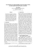
Figure 1: MIMO relay network with multiple source and destination pairs.
technique achieves higher capacity than other existing relay
schemes.
The rest of this paper is organized as follows. Section 2
shows a system model and the upper bound for the capacity
of the MIMO relay network. We describe the proposed and
existing relay schemes in Section 3. Numerical examples are
given in Section 4 . Finally, Section 5 concludes this paper.
Notation
E{
•} and tr{•} denote the expectation and trace operation,
respectively.
a stands for the norm of vector a,andsuper-
scripts T, H,and
∗ represent the transpose, the conjugate
transpose, and the conjugate operation, respectively. (A)
i
and
(A)
i, j
denote the ith row and (i, j)th entry of matrix A,re-
spectively. I
i
is the i × i identity matrix.
2. MIMO RELAY NETWORK
The MIMO relay network used in this paper is illustrated in
Figure 1. This paper assumes a one-hop relay network com-
prising L source and destination nodes, each of which has M
antennas, and K relay nodes, each of which has N antennas.
In addition, we assume that the relay nodes do not transmit
and receive simultaneously. In other words, two time slots are
required to send a message from the source to the destination
as shown in Figure 1.
First, M
× 1vectors
l
(l = 1, , L), destined for the lth
destination node, is sent to all relay nodes from the lth source
node without using any channel state information (CSI). The
N
× 1 vector received at the kth relay node is expressed as
y
k
=
L
l=1
H
k,l
s
l
+ n
k
,whereH
k,l
(k = 1, , K) is the N × M
MIMO channel matrix between the lth source node and the
kth relay node (backward channel), and n
k
refers to the N ×1
noise vector at the kth relay node with zero mean and covari-
ance matrix E
{n
k
n
H
k
}=σ
2
r
I
N
. We constrain the transmit-
ted signal power at the source node to E
{s
l
s
H
l
}=(P/M)I
M
,
where P is the total transmit power. A relay operation is per-
formed at the kth relay node by using N
× N relay matrix
W
k
to obtain N × 1 transmitted signal vector x
k
= E
k
W
k
y
k
,
where E
k
is a power coefficient resulting from total power
constraint E
{x
k
H
x
k
}=P. This can be expressed as
E
k
=
PM
P tr
W
k
H
k
H
W
k
H
k
+ Mσ
2
r
tr
W
k
H
W
k
,
(1)
where N
×LM matrix H
k
= [H
k,1
, , H
k,L
]. Finally, the M×1
receive v ector given by
r
l
=
K
k=1
G
k,l
x
k
+ z
l
(2)
is obtained at the lth destination node, where G
k,l
and z
l
are
the M
×N channel matrix between the kth relay node and the
lth destination node (forward channel), and the M
× 1noise
vector added a t the lth destination node with zero mean and
covariance matrix E
{z
l
z
H
l
}=σ
2
d
I
M
,respectively.
Using the cut-set theorem [13], the upper bound for the
capacity of the MIMO relay network is derived in [10]as
C
upper
= E
{Hk}
1
2
log
det
I
LM
+
P
Mσ
2
r
K
k=1
H
H
k
H
k
.
(3)
3. MIMO RELAY TECHNIQUES
In this paper, we assume that each relay node knows the CSI
of its own backward and forward channels. However, we do
not allow source nodes, relay nodes, and destination nodes
to exchange their CSI with other nodes.
3.1. ZF relaying scheme [11]
The ZF relaying scheme computes backward and forward ZF
matrices H
+
k
and G
+
k
that satisfy H
+
k
H
k
= I
LM
and G
k
G
+
k
=
I
LM
with LM × N matrix G
k
= [G
T
k,1
, , G
T
k,L
]
T
.Relayma-
trix W
k
for the ZF scheme is then written asW
k
= G
+
k
H
+
k
.
Tetsushi Abe et al. 3
Note here that the ZF scheme requires that N ≥ LM.In
this case, the effective signal-to-noise ratio (SNR) for the mth
data stream, λ
ZF
l,m
(m = 1, , M), at the lth destination node
is
λ
ZF
l,m
=
(P/M)
K
k=1
E
k
2
σ
2
r
K
k=1
E
2
k
H
+
k
m
2
+ σ
2
d
. (4)
From (4), we find that due to the transmit and receive ZF op-
erations the signals from K relay nodes are coherently com-
bined at the destination node, which leads to distributed ar-
ray gain [11].
3.2. GN/QR-P-QR relaying scheme
The first step of the GN/QR-P-QR scheme is to compute a
pre-group nulling filter at a relay node to suppress the signal
component f rom all source nodes except from the lth source
node. To accomplish this, we define N
× M(L − 1) matrix
H
(l)
k
≡ [H
k,1
, , H
k,l−1
, H
k,l+1
, , H
k,L
]. Note that the chan-
nel matrix between the lth source and kth relay node, H
k,l
,
is removed. Next, we perform the singular value decomposi-
tion (SVD) of H
(l)
k
as
H
(l)
k
=
U
(l)
k,1
··· U
(l)
k,L
−1
U
(l)
k,L
⎡
⎢
⎢
⎢
⎢
⎢
⎣
Λ
(l)
k,1
O
.
.
.
Λ
(l)
k,L
−1
OO
⎤
⎥
⎥
⎥
⎥
⎥
⎦
⎡
⎢
⎢
⎢
⎣
V
(l)H
k,1
.
.
.
V
(l)H
k,L
−1
⎤
⎥
⎥
⎥
⎦
,
(5)
where M
× M matrices Λ
(l)
k,1
, , Λ
(l)
k,L
−1
are diagonal matri-
ces, and N
× M matrices U
(l)
k,1
, , U
(l)
k,L
−1
and M(L − 1) × M
matrices V
(l)
k,1
, , V
(l)
k,L
−1
have orthonormal columns. N ×N −
M(L−1) matrix U
(l)
k,L
spans the null space of H
(l)
k
.MatrixU
(l)
k,L
is then multiplied to y
k
to obtain N − M(L − 1)× 1vectory
k,l
as
y
k,l
= U
(l)H
k,L
y
k
= U
(l)H
k,L
H
k,l
s
l
+ U
(l)H
k,L
n
k
. (6)
From (6), we see that U
(l)
k,L
removes the signal contribution
from all source nodes except that from the lth source node
due to the projection of the received signal vector onto the
null space of nondesired source nodes. A null space-based
method was also employed in [14] for the precoding in a
MIMO down link transmission.
The second step of the GN/QR-P-QR scheme is the trans-
formation of y
k,l
using N − M(L − 1) × N − M(L − 1) mat rix
Φ
k,l
to obtain vector y
k,l
= Φ
k,l
U
(l)H
k,L
y
k
. The computation of
Φ
k,l
will be described later in this section.
The third step is to compute the post-group nulling fil-
ter to suppress the transmitted signal to all destination nodes
except that to the lth destination node. Toward this goal, we
define N
× M(L − 1) matrix G
(l)
k
≡ [G
H
k,1
, , G
H
k,l
−1
, G
H
k,l+1
,
, G
H
k,L
].Next,weperformtheSVDofG
(l)
k
as
G
(l)
k
=
A
(l)
k,1
··· A
(l)
k,L
−1
A
(l)
k,L
×
⎡
⎢
⎢
⎢
⎢
⎢
⎣
Ω
(l)
k,1
O
.
.
.
Ω
(l)
k,L
−1
O ··· O
⎤
⎥
⎥
⎥
⎥
⎥
⎦
⎡
⎢
⎢
⎢
⎣
B
(l)H
k,1
.
.
.
B
(l)H
k,L−1
⎤
⎥
⎥
⎥
⎦
,
(7)
where M
×M matrices Ω
(l)
k,1
, , Ω
(l)
k,L
−1
are diagonal matrices,
and N
× M matrices A
(l)
k,1
, , A
(l)
k,L
−1
and M(L − 1) × M ma-
trices B
(l)
k,1
, , B
(l)
k,L
−1
have orthonormal columns. N × N −
M(L − 1) matr ix A
(l)
k,L
spans the null space of G
(l)
k
.Matrix
A
(l)
k,L
is then multiplied to y
k,l
to obtain N × 1vectory
k,l
=
A
(l)
k,L
Φ
k,l
U
(l)H
k,L
y
k
. Note here that similar to the ZF scheme, the
group nulling scheme also requires that N
≥ LM in order to
obtain null space matrices U
(l)
k,L
and A
(l)
k,L
.
The above three-step procedure is performed for all L
source and destination pairs (l
= 1, , L) at the kth relay
node. Finally, the N
× 1 signal vector transmitted from the
kth relay node is x
k
= E
k
L
l=1
y
k,l
= E
k
L
l=1
A
(l)
k,L
Φ
k,l
U
(l)H
k,L
y
k
.
In this case, the relaying matrix is written as W
k
=
L
l=1
A
(l)
k,L
Φ
k,l
U
(l)H
k,L
, and the received signal vector at the lth
destination is written from (2)as
r
l
=
K
k=1
E
k
G
k,l
A
(l)
k,L
Φ
k,l
U
(l)H
k,L
H
k,l
s
l
+
K
k=1
E
k
G
k,l
A
(l)
k,L
Φ
k,l
U
(l)H
k,L
n
k
+ z
l
.
(8)
Equation (8) shows that at the lth destination node, the sig-
nal contribution from all source nodes is removed except that
from the lth source node. Namely, we can establish an inde-
pendent MIMO relay link between the lth source and desti-
nation nodes that is characterized by M
× M MIMO channel
matrix E
k
G
k,l
A
(l)
k,L
Φ
k,l
U
(l)H
k,L
H
k,l
.
To compute the intermediate filter Φ
k,l
, we use the
QR-P-QR scheme [12]. The QR-P-QR relaying scheme
first performs the QRD of N
− M(L − 1) × M matri-
ces U
(l)H
k,L
H
k,l
and (G
k,l
A
(l)
k,L
)
H
as U
(l)H
k,L
H
k,l
= Q
1k,l
R
1k,l
and
(G
k,l
A
(l)
k,L
)
H
= Q
2k,l
R
2k,l
,whereN − M(L − 1) × M matri-
ces Q
1k,l
and Q
2k,l
have orthonormal columns, and M × M
matrices R
1k,l
and R
2k,l
are upper triangular matrices. By
using these results, the intermediate filter is computed as
Φ
k,l
= Q
2k,l
D
k,l
Q
H
1k,l
, where the M × M matrix, D
k,l
,
is a diagonal matrix whose mth diagonal entry is d
k,l,m
=
(R
H
2k,l
ΠR
1k,l
)
m,M−m+1
/(R
H
2k,l
ΠR
1k,l
)
m,M−m+1
and Π is an M×
M exchange matrix (see [12] for details). We can see that
Φ
k,l
consists of two orthogonal matrices, Q
1k,l
and Q
2k,l
,ob-
tained by the QRD in the backward and forward channels
with phase control matrix D
k,l
in between (for this reason
this scheme is called QR-P(Phase)-QR). Finally, by using the
4 EURASIP Journal on Wireless Communications and Networking
computed Φ
k,l
,(8)isrewrittenas
r
l
=
K
k=1
E
k
R
H
2k,l
D
k,l
R
1k,l
s
l
+
K
k=1
E
k
R
H
2k,l
D
k,l
Q
H
1k,l
U
(l)H
k,L
n
k
+ z
l
.
(9)
AnimportantnotehereisthatE
k
R
H
2k,l
D
k,l
R
1k,l
takes the lower
triangular form with positive scalars in diagonal entries. The
triangular structure provides the receive array gain by using
the SIC at the destination node to detect each data stream.
The positive diagonal entries achieved by the phase control
matrix enable the diagonal elements transmitted from K re-
lay nodes to be coherently combined at the destination node,
which obtains the distributed array gain.
The lth destination node simply performs SIC by using
the CSI of compound triangular channel
K
k
=1
E
k
R
H
2k,l
D
k,l
R
1k,l
to detect each of the multiple streams. The effective signal-to-
interference-plus-noise ratio (SINR) for the mth data stream
at the lth destination node can be expressed as
λ
QR
l,m
=
(P/M)
K
k=1
E
k
R
H
2k,l
D
k,l
R
1k,l
m,M−m+1
2
σ
2
r
K
k
=1
E
2
k
R
H
2k,l
D
k,l
m
2
+ σ
2
d
. (10)
Consequently, the ergodic capacity of the relay network with
total L S-D pairs is
C
QR
= E
{H
k
, G
k
}
1
2
L
l
=1
M
m
=1
log
2
1+λ
QR
l,m
. (11)
3.3. Achievable gains in the relay schemes
To evaluate the achievable gains of the GN/QR-P-QR relay
technique, we investigate its asymptotic c apacity when K ap-
proaches infinity. From (10)and(11), when K approaches
infinity, the capacity becomes
C
QR
=
1
2
L
l=1
M
m=1
log
2
⎛
⎜
⎜
⎜
⎜
⎜
⎝
1
+
(PK/M)
K
k=1
(1/K)E
k
R
H
2k,l
m,m
R
1k,l
M−m+1,M−m+1
2
σ
2
r
(1/K)
K
k=1
E
2
k
R
H
2k,l
D
k,l
m
2
+(1/K)σ
2
d
⎞
⎟
⎟
⎟
⎟
⎟
⎠
K→∞
−−−−→
ML
2
log
2
(K)
+
1
2
L
l=1
M
m=1
log
2
⎛
⎜
⎜
⎜
⎝
(P/M)E
E
k
R
H
2k,l
m,m
R
1k,l
M−m+1,M−m+1
2
σ
2
r
E
E
2
k
R
H
2k,l
D
k,l
m
2
⎞
⎟
⎟
⎟
⎠
,
(12)
where we use the approximation log
2
(1+x) ≈ log
2
x( x 1).
From (12), we see that the capacity of the GN/QR-P-QR
scheme scales with (LM/2) log
2
(K) asymptotically in K.The
term log
2
(K) indicates that the distributed ar ray gain of
the GN/QR-P-QR scheme is K. In addition, the prelog term
LM/2 implies that the multiplexing gain is LM/2, where 1/2
represents the loss when using two time slots in each trans-
mission. Furthermore, it was shown in [11] that the up-
per bound of the capacity in (3) and the capacity of the ZF
scheme asymptotically scale with (LM/2) log
2
(K). Thus, we
see that the GN/QR-P-QR scheme as well as the ZF scheme
exhibit the optimum capacity scaling for a large K value.
The difference between the GN/QR-P-QR scheme and
the ZF scheme is the available degrees of freedom remaining
after interference suppression among multiple S-D pairs. The
ZF scheme performs complete stream-wise nulling in both
the backward and forward channels. At each channel the ZF
scheme separates LM streams, which requires LM
− 1de-
grees of freedom. Thus, the degrees of freedom that remain
after the ZF relaying are N
− (LM − 1). On the other hand,
since the proposed scheme performs group-wise nulling, it
preserves a higher degree of freedom than the ZF scheme. To
be more specific, we define the N
− M(L − 1) × M decom-
posed forward MIMO channel for the lth S-D pair from (6)
as
H
k,l
≡ U
(l)H
k,L
H
k,l
. Assuming (H
k,l
)
i, j
are i.i.d. complex ran-
dom variables with zero mean and unit variance, (
H
k,l
)
i, j
has
the following statistical property:
E
H
k,l
∗
i, j
H
k,l
i
, j
=
⎧
⎨
⎩
1, i = i
, j = j
,
0, otherwise.
(13)
Proof. When i
= i
and j = j
,E{(
H
k,l
)
∗
i, j
(
H
k,l
)
i
, j
}=1be-
cause E
{H
H
k,l
H
k,l
}=I
M
and the norm of each column in U
(l)
k,l
is one. When i = i
and j = j
,E{(
H
k,l
)
∗
i, j
(
H
k,l
)
i
, j
}=0be-
cause (H
k,l
)
i, j
are mutually uncorrelated. When i = i
and
j
= j
,E{(
H
k,l
)
∗
i, j
(
H
k,l
)
i
, j
}=0 because the columns of U
(l)
k,l
are mutually orthogonal. Equation (13) is then proven.
We can see from (6)and(13) that the group nulling trans-
forms N
× M i.i.d. matrix H
k,l
to an N − M(L − 1) × M i.i.d.
matrix
H
k,l
. This shows that due to the group nulling, M(L −
1) degrees of freedom are lost for the lth S-D pair, but
H
k,l
still holds N−M(L−1) degrees of freedom. Further more, it is
straightforward that the same discussion holds for the back-
ward decomposed channel G
k,l
A
(l)
k,L
. Thus, after the group
nulling operations, the proposed scheme holds N
− M(L −1)
degrees of freedom, which are higher than that of ZF by
M
− 1. This additional degree of freedom is converted as the
receive array gain through the channel triangulation in (9)
using the QR-P-QR technique and the following SIC at the
destination node.
3.4. Other simple schemes
For GN-based relaying, we could simply employ an AF relay
scheme instead of the QR-P-QR scheme, which gives the in-
termediate fi lter Φ
k,l
= I
N−M(L−1)
. In this case, however, we
cannot obtain the distr ibuted array gain because signals from
K relay nodes are randomly combined at the destination
Tetsushi Abe et al. 5
node. In addition, [10, 15] describe another simple matched
filter (MF) relaying scheme in which each relay node per-
forms receive and transmit MF operations. For the MF relay-
ing, the relay matrix is expressed as W
k
= G
H
k
H
H
k
. Unlike the
ZF and the proposed schemes, this scheme does not require
that N
≥ LM, and the capacity still scales logarithmically
with the number of relay nodes [10].
4. NUMERICAL RESULTS
The ergodic capacities of the relaying schemes presented in
the previous section were evaluated. We obtained the capac-
ity plots of the upper bound, ZF, GN/QR-P-QR, GN/AF, and
MF. In addition, we evaluated as a reference the capacity of
QR-P-QR when all relay and destination nodes fully coop-
erate. To be more specific, we calculated the capacity of the
QR-P-QR scheme in a network comprising a source node
with LM transmit antennas, a relay node with KN anten-
nas, and a destination node with LM antennas. In this case,
the power constraints at the source and relay are LP and KP,
respectively. We assumed a flat fading channel in which each
component o f H
k
and G
k
is an i.i.d. complex random vari-
able with zero mean and unit variance. We set σ
2
r
= σ
2
d
and
identical transmit power P for all source and relay nodes. We
did not take into account path loss.
4.1. Capacity versus the number of relay nodes
Figure 2 shows the capacity versus the number of relay nodes
K for L = 2, M = 4, and N = 8. The total transmit power-
to-noise ratio (PNR
= P/σ
2
r
) was set to 20 dB. The graph
shows that the capacity of the GN/AF scheme is saturated
when K becomes large. This is because although the sepa-
ration of multiple S-D pairs is accomplished by the group
nulling, the signals relayed from multiple relay nodes are ran-
domly combined at each destination node due to the simple
AF relay operation, and thus the distributed array gain is not
obtained. On the other hand, we can see that the GN/QR-P-
QR scheme, ZF scheme, and MF scheme exhibit logarithmic
capacity scaling as does the upper bound of the capacity. This
is due to the fact that signal components from multiple re-
lay nodes are coherently combined at the destination node.
Furthermore, the GN/QR-P-QR scheme offers higher capac-
ity than the ZF scheme due to the hig her degree of freedom
converted to the receive array gain at the destination node as
described in Section 3.3 . The capacity of the MF scheme is
lower than that of the others due to its inability to suppress
actively the interference among S-D pairs. The capacity gap
between GN/QR-P-QR and the upper bound is due to the
imperfect cooperation among nodes. As mentioned in [10],
the capacity upper bound in (3) can be achieved if all the
relay nodes perform joint decoding and encoding. To exam-
ine this, we obtained the capacity of QR-P-QR when all the
relay nodes and all destination nodes cooperate. Note that
in this case, there is no need for GN. We can see that the
capacity of the QR-P-QR scheme with perfect node coop-
eration approaches the upper bound. Furthermore, when K
becomes larger the gap between the two becomes narrower.
60
50
40
30
20
10
0
Ergodic capacity (bps/Hz)
0 6 12 18 24 30
Number of relay nodes
Upper bound
QR-P-QR (perfect coop.)
GN/QR-P-QR
ZF
GN/AF
MF
Figure 2: Capacity versus the number of relay nodes (L = 2, M = 4,
N
= 8).
This can be br iefly explained as follows. The capacity up-
per bound in (3) only depends on the backward channel. On
the other hand, the capacity expressions of QR-P-QR in (10)
with (11) show that the noise power at destination node σ
2
d
becomes less significant when K becomes large. Thus, the ca-
pacity depends more on the backward channel and thus ap-
proaches closer to the upper bound. Therefore, if we allow
relay nodes to perform the joint relay operation, we could
approach closer to the bound. However, this requires all re-
lay nodes and all the destination nodes to exchange their CSI.
In addition, the joint relay operation requires the QRD of
KN
× LM matrix, which might be practically demanding in
terms of complexity. Figure 3 shows capacity plots for L
= 2,
M
= 2, and N = 4. A similar tendency is observed, but the
gap between GN/QR-P-QR and ZF is decreased. This is be-
cause the number of antennas at each node is reduced by half,
and thus the receive array gain obtained in the GN/QR-P-QR
scheme is decreased. Figure 4 shows capacity plots for L
= 4,
M
= 2, and N = 8. In this case, the total number of antennas
in the network is the same as in the case in Figure 2, but the
capacity obtained by each relay scheme is higher than that
in Figure 2 except for MF. This is because the total transmit
power in the network is increased due to the increased num-
ber of the S-D pairs.
4.2. Capacity versus PNR
Figures 5 and 6 show the capacity versus the PNR for L
= 2,
M
= 4, and N = 8forK = 2 and 8, respectively. The fig-
ures show that the GN/QR-P-QR and the GN/AF schemes
offer similar capacity for K
= 2. However, Figure 6 shows
that when K
= 8, GN/QR-P-QR outp erforms GN/AF due to
the distributed array gain. In both figures, the capacity of the
6 EURASIP Journal on Wireless Communications and Networking
35
30
25
20
15
10
5
0
Ergodic capacity (bps/Hz)
0 6 12 18 24 30
Number of relay nodes
Upper bound
QR-P-QR (perfect coop.)
GN/QR-P-QR
ZF
GN/AF
MF
Figure 3: Capacity versus the number of relay nodes (L = 2, M = 2,
N
= 4).
MF scheme is better than the other schemes in a low PNR
region due to the SNR gain of the matched filtering. How-
ever, the capacity saturates in a high PNR region due to the
interference among S-D pairs.
4.3. Effectiveness of spatially multiplexing
multiple S-D pairs
Figure 7 shows the capacity curves of the GN/QR-P-QR
scheme for L
= 2, M = 4, and N = 8withK = 2and8.Here,
we measured the capacity for two cases: time-division multi-
plexing (TDM) and spatial-division multiplexing (SDM) for
the two S-D pairs. Note that in the former case, only one
S-Dpairisactiveatanyinstant,andthusgroup nulling is
not needed. Figure 7 shows that in a low PNR region, TDM
provides higher capacity, but in higher PNR regions, SDM
offers significantly higher capacity, which matches results of
conventional studies on the trade-off between spatial mul-
tiplexing and beam-forming. Furthermore, the figure shows
that when K increases, the crosspoint of SDM and TDM is
shifted to lower PNR regions. This is because the effective
SNR at the destination node increases as K increases. Thus,
it is clear that it is more advantageous to multiplex spatially
multiple S-D pairs in a situation, where the PNR is relatively
high or the number of relay nodes is relatively large.
4.4. Capacity versus the number of antennas
at the relay node
Figure 8 shows the capacity of the GN/QR-P-QR and the ZF
schemes with various N for L
= 2andM = 4. K is set to 2
and 8. We can see that when the number of antennas per relay
node, N, increases, the capacity gap between the GN/QR-P-
60
50
40
30
20
10
0
Ergodic capacity (bps/Hz)
0 6 12 18 24 30
Number of relay nodes
Upper bound
QR-P-QR (perfect coop.)
GN/QR-P-QR
ZF
GN/AF
MF
Figure 4: Capacity versus the number of relay nodes (L = 4, M = 2,
N
= 8).
35
30
25
20
15
10
5
0
Ergodic capacity (bps/Hz)
0 5 10 15 20 25
PNR (dB)
Upper bound
QR-P-QR (perfect coop.)
GN/QR-P-QR
ZF
GN/AF
MF
Figure 5: Capacity versus PNR (L = 2, M = 4, N = 8, K = 2).
QR and the ZF schemes becomes smaller. This is because as
N becomes larger, both the GN and the ZF operations retain
enough degrees of freedom after the interference suppression
as shown in Section 3.3.
4.5. Complexity
Finally, Table 1 shows the computational complexity of the
relaying schemes. The complexities were measured as the
Tetsushi Abe et al. 7
35
30
25
20
15
10
5
0
Ergodic capacity (bps/Hz)
0 5 10 15 20 25
PNR (dB)
Upper bound
QR-P-QR (perfect coop.)
GN/QR-P-QR
ZF
GN/AF
MF
Figure 6: Capacity versus PNR (L = 2, M = 4, N = 8, K = 8).
35
30
25
20
15
10
5
0
Ergodic capacity (bps/Hz)
0 5 10 15 20 25
PNR (dB)
TDM
K
= 8
K
= 2
SDM
K
= 8
K
= 2
Figure 7: Capacity of GN/QR-P-QR: SDM versus TDM (L = 2,
M
= 4, N = 8).
number of required complex multiplications at each relay
node. We approximated the complexity by computing only
matrix inversion, multiplication, SVD, and QRD parts and
evaluated only terms with the highest order (cubic) in terms
of matrix size. First, we observe that the complexity of the MF
scheme is much lower than that of others due to its simple
operations. The ZF scheme needs only one matrix inversion
for both the backward and forward channel matrices (H
k
and
G
T
k
), but the matrix size N × LM is the largest. The GN/AF
scheme requires SVD for every S-D pair of both equivalent
45
40
35
30
25
20
15
10
Ergodic capacity (bps/Hz)
810121416
Number of antennas at relay nodes
GN/QR-P-QR
K
= 2
K
= 8
ZF
K
= 2
K
= 8
Figure 8: Capacity of GN/QR-P-QR versus ZF for various N(L =
2, M = 4).
backward and forward channel matrices (H
(l)
k
and G
(l)
k
), but
the matrix size N
× M(L − 1) is smal ler than that in ZF.
The GN/QR-P-QR scheme further requires QRD for every
S-D pair of both equivalent backward and forward channels
U
(l)H
k,L
H
k,l
and (G
k,l
A
(l)
k,L
)
H
, and their matrix size, N − M(L −
1) × M, is smaller than that in ZF. Thus, when the number
of S-D pairs is small, such as when (L, M, N)
= (2,2,4)and
(2, 4, 8), the GN-based relay schemes offer lower complexity
than the ZF due to the matrix size reduction. On the other
hand, when the number of S-D pairs becomes larger, such
as when (L, M, N)
= (4, 2, 8), the ZF scheme offers lower
complexity due to fewer matrix operations. Therefore, when
the number of S-D pairs is small, the GN/QR-P-QR scheme
achieves higher capacity with lower complexity than the ZF
scheme.
5. CONCLUDING REMARKS
In this paper, we proposed a relay technique for a MIMO re-
lay network with multiple S-D pairs. The group nulling tech-
nique projects the receive and transmitted signal vectors at
the relay node onto the null space of the signals of nonde-
sired S-D pairs, so the multiple S-D MIMO relay channel
is decomposed into parallel independent MIMO channels.
To each decomposed MIMO relay link, the QR-P-QR tech-
nique is applied. This relaying architecture preserves a higher
degree of freedom in the MIMO relay channel than the ZF
scheme and enables coherent combination of the signals at
the destination to achieve distributed array gain.Weana-
lyzed the asymptotic capacity of the proposed relay technique
and clarified its achievable gains. Numerical examples con-
firmed that the proposed relay scheme achieves higher capac-
ity than other existing relay schemes. It should be mentioned,
8 EURASIP Journal on Wireless Communications and Networking
Table 1: Computational complexity per relay node (number of complex multiplications), (A = M(L − 1), B = N − M(L − 1)).
Complexity (L, M, N) = (2,2,4) (L, M, N) = (2,4,8) (L, M, N) = (4, 2, 8)
MF N(ML)
2
64 512 512
ZF
3N
2
(ML)+2(ML)
3
+ N
3
×
2+N
3
832 6656 6656
GN/AF
3N
2
A + N
3
×
L × 2+N
2
A × L 704 5632 14048
GN/QR-P-QR
3N
2
A + N
3
×
L × 2
816 6528 14848
+
3B
2
M − 3/2BM
2
+ M
3
×
L × 2
+
2MB
2
+ N
2
B
×
L
however, that the requirement for the number of antennas,
N
≥ LN, in the proposed scheme as well as in the ZF relay
scheme could still be a limiting factor in some application
scenarios. In addition, since the relay techniques described in
this paper assume perfect CSI knowledge for both the back-
ward and for ward MIMO channels at each relay terminal,
investigation of their capacity with imperfect CSI is an im-
portant future research topic.
ACKNOWLEDGMENT
The authors thank Mr. Katsutoshi Kusume for his helpful
discussion regarding the complexity issues.
REFERENCES
[1] M. Gastpar and M. Vetterli, “On the capacity of wireless net-
works: the relay case,” in Proceedings of the 21st Annual Joint
Conference of the IEEE Computer and Communications Soci-
eties (INFOCOM ’02), vol. 3, pp. 1577–1586, New York, NY,
USA, June 2002.
[2] I. E. Telatar, “Capacity of multi-antenna Gaussian channels,”
European Transactions on Telecommunications, vol. 10, no. 6,
pp. 585–595, 1999.
[3] G. J. Foschini and M. J. Gans, “On limits of wireless com-
munications in a fading environment when using multiple
antennas,” Wireless Personal Communications,vol.6,no.3,pp.
311–335, 1998.
[4] G. G. Raleigh and J. M. Cioffi, “Spatio-temporal coding for
wireless communication,” IEEE Transactions on Communica-
tions, vol. 46, no. 3, pp. 357–366, 1998.
[5] J. H. Winters, “On t he capacity of radio communication sys-
tems with diversity in a Rayleigh fading environment,” IEEE
Journal on Selected Areas in Communications,vol.5,no.5,pp.
871–878, 1987.
[6] A. Goldsmith, S. A. Jafar, N. Jindal, and S. Vishwanath, “Ca-
pacity limits of MIMO channels,” IEEE Journal on Selected Ar-
eas in Communications, vol. 21, no. 5, pp. 684–702, 2003.
[7] G. Caire and S. Shamai, “On the achievable throughput of a
multiantenna Gaussian broadcast channel,” IEEE Transactions
on Information Theory, vol. 49, no. 7, pp. 1691–1706, 2003.
[8] S. Vishwanath, N. Jindal, and A. Goldsmith, “Duality,
achievable rates, and sum-rate capacity of Gaussian MIMO
broadcast channels,” IEEE Transactions on Information Theory,
vol. 49, no. 10, pp. 2658–2668, 2003.
[9] W. Yu and J. M. Cioffi, “Sum capacity of Gaussian vector
broadcast channels,” IEEE Transactions on Information Theory,
vol. 50, no. 9, pp. 1875–1892, 2004.
[10] H. B
¨
olcskei, R. U. Nabar,
¨
O. Oyman, and A. J. Paulraj, “Ca-
pacity scaling laws in MIMO relay networks,” IEEE Transac-
tions on Wireless Communications, vol. 5, no. 6, pp. 1433–1444,
2006.
[11] R. U. Nabar,
¨
O. Oyman, H. B
¨
olcskei, and A. J. Paulraj, “Capac-
ity scaling laws in MIMO wireless networks,” in Proceedings of
Allerton Conference on Communication, Control, and Comput-
ing, pp. 378–389, Monticello, Ill, USA, October 2003.
[12] H. Shi, T. Abe, T. Asai, and H. Yoshino, “A relaying scheme us-
ing QR decomposition with phase control for MIMO wireless
networks,” in Proceedings of IEEE International Conference on
Communications (ICC ’05), vol. 4, pp. 2705–2711, Seoul, Ko-
rea, May 2005.
[13] T. M. Cover and J. A. Thomas, Elements of Informat ion Theory,
John Wiley & Sons, New York, NY, USA, 1991.
[14] L U. Choi and R. D. Murch, “A transmit preprocessing tech-
nique for multiuser MIMO systems using a decomposition ap-
proach,” IEEE Transactions on Wireless Communications, vol. 3,
no. 1, pp. 20–24, 2004.
[15] H. B
¨
olcskei and R. U. Nabar, “Realizing MIMO gains without
user cooperation in large single-antenna wireless networks,” in
Proceedings of IEEE International Symposium on Information
Theory, p. 18, Chicago, Ill, USA, June-July 2004.
Tetsushi Abe received his B.S. degree and
M.S. degree in electrical and electronic en-
gineering from Tokyo Institute of Technol-
ogy, Tokyo, Japan, in 1998 and 2000, re-
spectively. During 1998-1999, he studied
in the Department of Electrical and Com-
puter Engineering in University of Wiscon-
sin, Madison, USA, under the scholarship
exchange student program offered by the
Japanese Ministry of Education. He joined
NTT DoCoMo, Inc., in 2000. Since 2005, he has been with Do-
CoMo Euro-Labs. He has conducted researches on signal pro-
cessing for wireless communications: multiple-input and multiple-
output (MIMO) transmission, space-time turbo equalization, relay
transmission, and OFDM transmission. He is a Member of IEEE
and IEICE.
Tetsushi Abe et al. 9
Hui Shi received his B.S. degree in me-
chanic engineering from Dalian University
of Technology, Dalian, China, in 1998 and
M.S. degree in electrical and e lectronic en-
gineering from Nagoya University, Nagoya,
Japan, in 2002. Since 2002, he has been
with the Research Laboratories at NTT Do-
CoMo, Inc. His research interests cover
the wireless network systems, relay net-
works, multiple-input and multiple-output
(MIMO) transmission, and information theory issues. He is a
Member of IEEE and IEICE.
Takahiro Asai received the B.E. and M.E.
degrees from Kyoto U niversity, Kyoto,
Japan, in 1995 and 1997, respectively. In
1997, he joined NTT Mobile Communica-
tions Network, Inc. (now NTT DoCoMo,
Inc.). Since joining NTT Mobile Communi-
cations Network, Inc., he has been engaged
in the research of signal processing for mo-
bile radio communication. He is a Member
of IEEE.
Hitoshi Yoshino received the B.S. and M.S.
degrees in electrical engineering from the
Science University of Tokyo, Tokyo, Japan,
in 1986 and 1988, respectively, and the
Dr.Eng. degree in communications and in-
tegrated systems from the Tokyo Institute
of Technology, Tokyo, Japan, in 2003. From
1988 to 1992, he was with Radio Communi-
cation Systems Laboratories, Nippon Tele-
graph and Telephone Corporation (NTT),
Japan. Since 1992, he has been with NTT Mobile Communications
Network, Inc. (currently, NTT DoCoMo, Inc.), Japan. Since join-
ing NTT DoCoMo, he has been engaged in the areas of mobile
radio communication systems and digital signal processing. From
1998 to 1999, he was at the Deutsche Telekom Technologiezentrum,
Darmstadt, Germany, as a Visiting Researcher. He is currently an
Executive Research Engineer in Wireless Laboratories, NTT Do-
CoMo, Inc. He received the Young Engineer Award and the Excel-
lent Paper Award from the Institute of Electronics, Information,
and Communication Engineers (IEICE) of Japan both in 1995. He
is a Member of IEEE.