Báo cáo hóa học: " Research Article An Overview of Multigigabit Wireless through Millimeter Wave Technology: Potentials and Technical Challenges" docx
Bạn đang xem bản rút gọn của tài liệu. Xem và tải ngay bản đầy đủ của tài liệu tại đây (901.38 KB, 10 trang )
Hindawi Publishing Corporation
EURASIP Journal on Wireless Communications and Networking
Volume 2007, Article ID 78907, 10 pages
doi:10.1155/2007/78907
Research Article
An Overview of Multigigabit Wireless through Millimeter Wave
Technology: Potentials and Technical Challenges
Su Khiong Yong
1
and Chia-Chin Chong
2
1
Communication and Wireless Connectivity Labarotory, Samsung Advanced Institute of Technology,
P.O. Box 111, Suwon 440-600, South Korea
2
NTT DoCoMo USA Labs, 3240 Hillview Avenue, Palo Alto, CA 94304, USA
Received 14 June 2006; Revised 11 September 2006; Accepted 14 September 2006
Recommended by Peter F. M. Smulders
This paper presents an overview of 60 GHz technology and its potentials to provide next generation multigigabit wireless commu-
nications systems. We begin by reviewing the state-of-art of the 60 GHz radio. Then, the current status of worldwide regulatory
efforts and standardization activities for 60 GHz band is summarized. As a result of the worldwide unlicensed 60 GHz band allo-
cation, a number of key applications can be identified using millimeter-wave technology. Despite of its huge potentials to achieve
multigigabit wireless communications, 60 GHz radio presents a series of technical challenges that needs to be resolved before its
full deployment. Specifically, we will focus on the link budget analysis from the 60 GHz radio propagation standpoint and high-
light the roles of antennas in establishing a reliable 60 GHz radio.
Copyright © 2007 S. K. Yong and C C. Chong. This is an open access article distributed under the Creative Commons Attribution
License, which permits unrestricted use, dist ribution, and reproduction in any medium, provided the original work is properly
cited.
1. INTRODUCTION
Despite millimeter wave (mmWave) technology has been
known for many decades, the mmWave systems have mainly
been deployed for military applications. With the advances
of process technologies and low-cost integration solutions,
mmWave technology has started to gain a great deal of
momentum from academia, industry, and standardization
body. In a very broad term, mmWave can be classified as
electromagnetic spec trum that spans between 30 GHz to
300 GHz, which corresponds to wavelengths from 10 mm
to 1 mm [1].Inthispaper,however,wewillfocusspecifi-
cally on 60 GHz radio (unless otherwise specified, the terms
60 GHz and mmWave can be used interchangeably), which
has emerged as one of the most promising candidates for
multigigabit wireless indoor communication systems [2].
60 GHz technology offers various advantages over current
or existing communications systems [3]. One of the decid-
ing factors that makes 60 GHz technology gaining significant
interest recently is due to the huge unlicensed bandwidth
(up to 7 GHz) available worldwide. While this is compara-
ble to the unlicensed bandwidth allocated for ult ra wideband
(UWB) purposes [4],60GHzbandwidthiscontinuousand
less restricted in terms of power limits. This is due to the fact
that UWB system is an overlay system and thus subject to
very strict and different regulations [5]. The large bandwidth
at 60 GHz band is one of the largest unlicensed bandwidths
being allocated in history. This huge bandwidth represents
high potentials in terms of capacity and flexibility that makes
60 GHz technology particularly attractive for gigabit wireless
applications. Furthermore, 60 GHz regulation allows much
higher transmit power compared to other existing wireless
local area networks (WLANs) and wireless personal area net-
works (WPANs) systems. The higher transmit power is nec-
essary to overcome the higher path loss at 60 GHz. While the
high path loss seems to be disadvantage at 60 GHz, it however
confines the 60 GHz operation to within a room in an in-
door environment. Hence, the effective interference levels for
60 GHz are less severe than those systems located in the con-
gested 2–2.5 GHz and 5–5.8 GHz regions. In addition, higher
frequency reuse can also be achieved per indoor environment
thus allowing a very high throughput network. The compact
size of the 60 GHz radio also permits multiple antennas so-
lutions at the user terminal that are otherwise difficult, if not
impossible, at lower frequencies. Comparing to 5 GHz sys-
tem, the form factor of mmWave systems is approximately
140 times smaller and can be conveniently integrated into
consumer electronic products.
2 EURASIP Journal on Wireless Communications and Networking
10G1G100M10M1M
Data rate (bps)
1
10
100
Disatnce (m)
Bluetooth
802
15.4a
802.11b
802.11a
802.11n
Home RF
802.15.3c
UWB
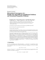
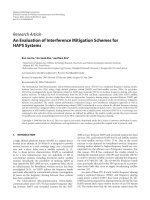
Figure 1: Data rates and range requirements for WLAN and WPAN
standards and applications. Millimeter wave technology, that is,
IEEE 802.15.3c is aiming for very high data rates.
Despite the various advantages offered, mmWave based
communications suffer a number of critical problems that
must be resolved. Figure 1 shows the data r a tes and range re-
quirements for number of WLAN and WPAN systems. Since
there is a need to distinguish between different standards
for broader market exploitation, the IEEE 802.15.3c is posi-
tioned to provide gigabit rates and longer operating range. At
these rate and range, it wil l be a nontriv ial task for mmWave
systems to provide sufficient power margin to ensure reli-
able communication link. Furthermore, delay spread of the
channel under study is another limiting factor for high speed
transmissions. Large delay spread values can easily increase
the complexity of the system beyond the practical limit for
equalization.
The remainder of the paper is organized as follows:
Section 2 describes the worldwide regulatory efforts and
standardization activities; Section 3 presents a number of ap-
plication scenarios and highlights the requirements for a spe-
cific application namely uncompressed high definition video
streaming; Section 4 analyses the achievable data rate in both
additive white Gaussian noise (AWGN) and fading channel
based on the application requirements described in Section 3
and the roles of antenna in 60 GHz communications are also
discussed; Section 5 describes the technical challenges that
need to be resolved ahead for the full deployment of 60 GHz
radio; finally, in Section 6 appropriate conclusions wrap up
this paper.
2. WORLDWIDE REGULATIONS AND
STANDARDIZATION
This section discusses the current status of worldwide regula-
tion and standardization efforts for 60 GHz band. Regulatory
body in United States, Japan, Canada, and Australia have al-
ready set frequency bands and regulations for 60 GHz oper-
ation while in Korea and Europe intense efforts are currently
underway. A summary for the issued and proposed frequency
allocations and main specifications for radio regulation in a
number of countries is given in Table 1.
2.1. 60 GHz regulations in North America
In 2001, the United States Federal Communication Commis-
sions (FCC) allocated 7 GHz in the 54–66 GHz band for unli-
censed use [6]. In terms of the power limits, FCC rules allow
emission with average power density of 9 μW/cm
2
at 3 me-
ters and maximum power density of 18 μW/cm
2
at 3 meters,
from the radiating source. These figures translate to average
equivalent isotropic radiated power (EIRP) and maximum
EIRP of 40 dBm and 43 dBm, respectively. FCC also specified
the total maximum transmit power of 500 mW for an emis-
sion bandwidth g reater than 100 MHz.
The devices must also comply with the radio frequency
(RF) radiation exposure requirements specified in [6, Sec-
tions 1.307(b), 2.1091, and 2.1093]. After taking the RF safety
issues into account, the maximum transmit power is limited
to 10 dBm. Furthermore, each transmitter must transmit at
least one transmitter identification within one-second inter-
val of the signal transmission. It is important to note that the
60 GHz regulation in Canada, which is regulated by Indus-
try Canada Spectrum Management and Telecommunications
(IC-SMT) [7], is harmonized with the US.
2.2. 60 GHz regulations in Japan
In year 2000, the Ministry of Public Management, Home Af-
fairs, Posts, and Telecommunications (MPHPT) of Japan is-
sued 60 GHz radio regulations for unlicensed utilization in
the 59–66 GHz band [8]. The 54.25–59 GHz band is however
allocated for licensed use. The maximum transmit power for
the unlicensed use is limited to 10 dBm with maximum al-
lowable antenna gain of 47 dBi. Unlike in North America,
Japanese regulations specified that the maximum transmis-
sion bandwidth must not exceed 2.5 GHz. There is no spec-
ification for RF radiation exposure and transmitter identifi-
cation requirements.
2.3. 60 GHz regulation in Australia
Following the release of regulations in Japan and North
America, the Australian Communications and Media Au-
thority (ACMA) has taken a similar step to regulate 60 GHz
band [9]. However, only 3.5 GHz bandwidth is allocated for
unlicensed use, that is, from 59.4–62.9 GHz. The maximum
transmit power and maximum EIRP are limited to 10 dBm
and 51.7 dBm, respectively. The data communication trans-
mitters that operate in this frequency band are limited to land
and maritime deployments.
2.4. 60 GHz regulation in Korea
In June 2005, mmWave Frequency Study Group (MFSG) was
formed under the Korean Radio Promotion Association [12].
The MFSG has recommended a 7 GHz unlicensed spectrum
from 57–64 GHz without limitation on the types of applica-
tion to be used. The maximum transmit power is the same as
in Japan a nd Australia, that is, 10 dBm but the maximum al-
lowable antenna gain is still under discussion. Currently, the
S. K. Yong and C C. Chong 3
Table 1: Frequency band plan and limits on transmit power, EIRP, and antenna gain for various countries.
Region
Unlicensed
Tx Power EIRP
Max. Antenna
Ref Comment
bandwidth (GHz) gain
USA 7 GHz (57–64) 500 mW (max)
40 dBm (ave)
43 dBm (max)
#
NS
[6]
For bandwidth> 100 MHz
+
Translate from average
PD of 9 uW/cm
2
at 3 m
#
Translate from average
PD of 18 uW/cm
2
at 3 m
Canada 7 GHz (57–64) 500 mW (max)
40 dBm (ave)
43 dBm (max)
#
NS
[7]
For bandwidth> 100 MHz
+
Translate from average
PD of 9 uW/cm
2
at 3 m
#
Translate from average
PD of 18 uW/cm
2
at 3 m
Japan
7 GHz (59–66), max
10 mW (max) NS 47 dBi
[8]
2.5GHz
Australia 3.5GHz(59.4–62.9) 10 mW (max) 150 W (max) NS
[9]
Limited to land and
maritime deployment
Korea 7 GHz (57–64) 10 mW (max) TBD TBD
[10]
Frequency allocation
expected in Jun, 06
Radio regulation expected
by End of 06
Europe
9 GHz (57–66), min
20 mW (max) 57 dBm (max) 37 dBi
[11]
Recommendation by ETSI
500 MHz
60 GHz regulation efforts in Korea are in the final stage of
public hearing forum [10] in which the frequency band allo-
cation is expected to take place in June 2006. The final radio
regulation is scheduled to be completed by December 2006.
2.5. 60 GHz regulation in Europe
The European Telecommunications Standards Institute
(ETSI) and European Conference of Postal and Telecommu-
nications Administrations (CEPT) have been working closely
to establish a legal framework for the deployment of unli-
censed 60 GHz devices. In general, 59–66 GHz band has been
allocated for mobile services without specific decision on the
regulations. The CEPT Recommendation T/R 22–03 has pro-
visionally recommended the use of 54.25–66 GHz band for
terrestrial and fixed mobile systems [13]. However, this pro-
visional allocation has been recently withdrawn.
The European Radiocommunication Committee (ERC)
considered the use of 57–59 GHz band for fixed services
without requiring frequency planning [14]. Later, the Elec-
tronic Communications Committee (ECC) within CEPT
recommended the use of point-to-point fixed services in
the 64–66 GHz band [15]. In the most recent develop-
ment, ETSI proposed 60 GHz regulations to be considered
by ECC for WPAN applications [11]. Under this proposal,
9 GHz unlicensed spectrum is allocated for 60 GHz opera-
tion. This band represents the union of the bands currently
approved and under proposed as described from Section 2.1
to Section 2.4. In addition, a minimum spectrum of
500 MHz is required for the transmitted signal with maxi-
mum EIRP of 57 dBm. No specification is given for the maxi-
mum transmit p ower and maximum antenna gain. This pro-
posal is expected to be submitted to ECC by September 2006
and ETSI would request ECC to finalize the new deliverable
proposal by the end of 2006.
2.6. Industrial standardization efforts
The first international industry standard that covers 60 GHz
band is the IEEE 802.16 Standard for local and metropoli-
tan area networks [16]. However, this is a licensed band
and is used for line-of-sight (LOS) outdoor communica-
tions for last mile connectivity. In Japan, two standards re-
lated to 60 GHz band were issued by Association of Radio
Industries and Business (ARIB), that is, the ARIB-STD T69
[17] and ARIB-STD T74 [18]. The former is the standard
for mmWave video transmission equipment for specified
low-power radio station (point-to-point system), while the
latter is the standard for mmWave ultra high-speed WLAN
for specified low-power radio station (point-to-multipoint).
Both standards cover the 59–66 GHz band defined in Japan.
The interest in 60 GHz radio continued to grow with
the formation on mmWave Interest Group and Study Group
within the IEEE 802.15 Working Group for WPAN. In March
4 EURASIP Journal on Wireless Communications and Networking
2005, the IEEE 802.15.3c Task Group (TG3c) was formed to
develop an mmWave-based alternative physical layer (PHY)
for the existing IEEE 802.15.3 WPAN Standard 802.15.3-
2003 [2]. The developed PHY is aimed to support minimum
data rate of 2 Gbps over few meters with optional data rates
in excess of 3 Gbps. This is the first standard that addresses
multigigabit wireless systems and will form the key solutions
to many data rates starving applications especially related
wireless multimedia distribution.
In other development, WiMedia Alliance has recently an-
nounced the formation of WiMedia 60 GHz Study Group
with the aim to provide recommendations to the WiMe-
dia Board of Directors on the feasibility issues related to
60 GHz technology. Decision will be taken in the near future
about WiMedia direction and involvement in 60 GHz market
[19].
3. APPLICATION SCENARIOS
With the allocated bandwidth of 7 GHz in most coun-
tries, mmWave radio has become the technology enabler
for many gigabit transmission applications that are tech-
nically constrained at lower frequency. Due to the higher
path loss and oxygen absorption of 15 dB/km around 60 GHz
band, 60 GHz radio is thus limited for indoor applica-
tions. A number of applications are envisioned such as
high definition multimedia interface (HDMI) cable replace-
ment/uncompressed h igh definition (HD) video stream-
ing, mobile distributed computing, wireless docking sta-
tion, wireless gigabit Ethernet, fast bulky file transfer, wire-
less gaming, and so forth. However, as shown in the IEEE
802.15.3c meeting in Jacksonville, FL, USA, TG3c envisaged
the wireless HD streaming is the most attractive application
among the others [20]. We will therefore concentrate on this
particular application scenario and describe the technical re-
quirements for its operation.
Depending on the progressive scan resolution and num-
ber of pixels per line, the data rates required varies from
several hundreds Mbps to few Gbps. The latest commer-
cially available high definition television (HDTV) resolution
is 1920
1080 with refresh r ate of 60 Hz. Considering RGB
video formats w ith 8 bits per channel per pixel, the required
data rates turns out to be approximately 3 Gbps. In the fu-
ture, a higher number of bits per channel as well as higher
refresh rates are expected to improve the quality of next gen-
eration HDTV. This easily scales the data rate to well be-
yond 5 Gbps. Table 2 summarizes data rates requirements
for some current and future HDTV specifications. Further-
more, uncompressed HD streaming is an asymmetry trans-
mission with significantly different data flow in both up-
link and downlink directions. This application also requires
very low latency of tens of microseconds and very low er-
ror probability down to 10
12
to ensure high quality video.
Tabl e 3 recapitulates the key requirements for uncompressed
HD video streaming as well as outlines the large scale param-
eters for home environment and conference room within an
office environment [21], which this application is mainly de-
ployed.
Table 2: Data rate requirements for different resolutions, frame
rates, and numbers of bits per channel per pixel for HDTV stan-
dard.
Pixels per Active lines Frame # of bits per Data rate
line per picture rate channel per pixel (Gbps)
1280 720 24 24 0.531
1280 720 30 24 0.664
1440 480 60 24 0.995
1280 720 50 24 1.106
1280 720 60 24 1.327
1920 1080 50 24 2.488
1920 1080 60 24 2.986
1920 1080 60 30 3.732
1920 1080 60 36 4.479
1920 1080 60 42 5.225
1920 1080 90 24 4.479
1920 1080 90 30 5.599
4. FEASIBILITY STUDY
In this section, we perform a basic feasibility study on the
60 GHz radio technology. The study is based on the applica-
tion scenarios described in Section 3 for the uncompressed
HD video streaming. We begin by analyzing the achievable
Shannon capacity for an omni-directional antenna at both
sides of the transmitter (Tx) and receiver (Rx). Then, we
determine what is the minimum gain required in order to
operate under certain environment and target specifications.
The analysis also considers the effectofmultipathandinves-
tigates the role of antenna to provide sufficient power margin
for 60 GHz wireless communications. Unless otherwise spec-
ified, the parameters in Tab le 4 are assumed in our analysis.
4.1. Power margin
Using the above par ameters, one can compute the ratio of
signal power to noise power at the Rx as given by
SNR
= P
T
+ G
T
+ G
R
PL
0
PL(d) I
L
KT +10log
10
(B) NF
,
(1)
where G
T
and G
R
denote the transmit and received antenna
gain, respectively. Inserting (1) into the well-known Shannon
capacity formula, that is, C
= B log
2
(SNR +1), the maximum
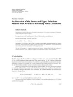
achievable capacity in AWGN can be computed. Figure 2
shows the Shannon capacity limit for indoor office in LOS
and non-LOS (NLOS) case using omni-omni antenna setup.
It can be observed that for LOS condition, a 5 Gbps data rates
is impossible at any distance. On the other hand, the oper-
ating distance for NLOS condition is limited to below 3 m
though the capacity for NLOS decreases more drastically as
a function of distance. To improve the capacity for a given
operating distance, one can either increase the bandwidth or
signal-to-noise ratio (SNR) or both. It can also be seen from
Figure 2 that increasing the bandwidth used by more than
4 times only significantly improves the capacity for distance
below 5 m. Beyond this distance, the capacity for the 7 GHz
case only slightly above the case of 1.5 GHz bandw idth, since
S. K. Yong and C C. Chong 5
Table 3: Key requirements for uncompressed HD video streaming application and the large scale fading parameters for conference room
and home environment, respectively.
Applications Data Rate BER Data type Environment n Shadowing Ref
Uncompressed
HD video
streaming
0.05–5.5Gbps 1.00E-12 Isochronous
Home 5–10 m
(LOS/NLOS)
1.55/2.44 1.5/6.2
[22]
Conf. room
20 m
(LOS/NLOS)
1.77/3.83 6/7.6
[23]
Table 4: Parameters used in the analysis.
Tx Power, PT 10 dBm
Center frequency, f
c
60 GHz
Noise figure, NF
6dB
Implementation loss, IL
6dB
Thermal noise, N
174 dBm/MHz
Bandwidth, B
1.5GHz
Distance
20 m
Pah loss at 1 m, PL
0
57.5dB
the SNR at the Rx is reduced considerably at longer distance
due to higher path loss. On the other hand, the overall capac-
ity over the considered distance increases notably if a 10 dBi
transmit antenna gain is employed as compared to the omni-
directional antenna for both 1.5 GHz and 7 GHz bandwidths.
This clearly shows the importance of antenna gain in provid-
ing a very high data application at 60 GHz which is not pos-
sible to be provided with omni-omni antenna configuration.
But the question remains, how much gain is required?
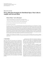
To answer that question, the capacity as a function of
combined Tx and Rx gain for operating distance at 20 m is
plotted as depicted in Figure 3. To achieve 5Gbps at 20m,
a combined gain of 25 dBi and 37 dBi are required for LOS
and NLOS, respectively. This seems to be practical value since
it is a combined Tx and Rx gain. However, to achieve the
same data rates in multipath channel, higher gain is needed
to overcome the fading margin. Now consider what addi-
tional gains are required in a more realistic scenario where
the propagation channel is corrupted by multipath fading in-
stead of AWGN. To ease the analysis, we u se the closed-form
bit error probability (BEP) results for the noncoherent binary
frequency-shift keying (BFSK) [22]. Specifically, we use
P
b
=
1+K
2+2K + γ
b
exp
Kγ
b
2+2K + γ
b
,(2)
where K and
γ
b
are the Ricean K-factor and the average
energy-per-bit-to-noise ratio, respectively. Equation (2)can
be reduced to the case of Rayleigh fading when K
= 0and
simultaneously approximates the AWGN case when K
.
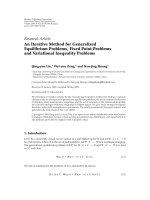
Clearly from Figure 4, one can see that for uncoded sys-
tem, the required additional combined Tx-Rx g ain becomes
prohibitively impractical in order to achieve BEP of 10
12
in
Ricean and Rayleigh fading channels, respectively, over the
AWGN case. Thus, coded systems, diversity systems or/and
20181614121086420
Distance (m)
10
6
10
7
10
8
10
9
10
10
10
11
Capacity (bps)
Omni-omni, Tx power = 10 dBm, NF = 6dB,
implementation loss
= 6dB,BW= 1.5GHz
Free space path loss
Office LOS, n
= 1.77
Office NLOS, n
= 3.85
Office NLOS, n
= 3.85, BW = 7GHz
Office NLOS, n
= 3.85, Tx gain = 10 dBi
Figure 2: Shannon capacity limits for the case of indoor office using
omni-omni antenna setup.
high gain antenna systems have to be used in order to reduce
the fading margin associated with the multipath channel. For
diversity technique employing maximum ratio combining in
a flat Rayleigh fading channel, the BEP for uncoded BFSK
can be expressed as [22]
P
b
=
1
2
(1
μ)
L
L
1
k=0
L 1+k
k
1
2
(1 + μ)
k
,(3)
where L is the number of diversity channels that are assumed
to be statistically independent Rayleigh fading and μ is given
as
μ
=
γ
c
γ
c
+2
,(4)
where
γ
c
is the average SNR per channel. As shown in
Figure 4, the use of diversity technique for the case of two and
four channels provides diversity gain of approximately 65 dB
to 80 dB over the single channel at BEP of 10
12
.However,in
6 EURASIP Journal on Wireless Communications and Networking
80757065605550454035302520151050
Combined Tx-Rx gain (dBi)
10
6
10
7
10
8
10
9
10
10
10
11
Capacity (bps)
Tx power = 10 dBm, NF = 6dB,
implementation loss
= 6dB,BW= 1.5GHz
Free space
Office LOS, n
= 1.77, d = 20 m
Office NLOS, n
= 3.85, d = 20 m
Figure 3: The required combined Tx-Rx antenna gain to achieve a
target capacity.
practice these gains are expected to be much lower as chan-
nel is not independent and identical distributed and subject
to fading correlation. Similarly, the use of channel coding can
improve the BEP significantly over the uncoded case. In our
example, the use of Golay (24,12) code (with Hamming dis-
tance d
min
= 8) is shown to have coding gain of approxi-
mately 92 dB over the single channel Rayleigh fading case.
For the cases discussed above, to achieve 5 Gbps data rate
at BEP of 10
12
, in the case of Rayleigh fading channel and
assuming that bandwidth is equal to the data rate, one can
compute the power margin as the difference between the re-
ceived E
b
/N
0
over the required E
b
/N
0
to achieve the target
BEP. The power margin for the case of Rayleigh channel with
coding and diversity as well as AWGN can b e shown to be
given by
M
Ray Coded
= G
T
+ G
R
61,
M
Ray Div
= G
T
+ G
R
73,
M
AWGN
= G
T
+ G
R
37.
(5)
For high quality video transmission link at 60 GHz, a suffi-
ciently large link margin is required due to the highly vari-
able shadowing and human blockage effects. Experiments
show that the shadowing effect is log-normally distributed
with zero mean and standard deviation as high as 7–10 dB
[23, 24]. On the other hand, the effect of human block-
age varies between 18–36 dB [25, 26]. Assuming a margin of
10 dB is required, then the required combined Tx-Rx gain
for the three cases given in (5) are 71 dB, 83 dB, and 47 dB,
respectively. From the regulatory standpoint, we see that the
maximum transmit antenna gain that is allowed for a Tx
120110100908070605040302010
E
b
/N
0
(dB)
10
12
10
10
10
8
10
6
10
4
10
2
BEP
Uncoded, Rayleigh
Uncoded, K
= 8dBRicean
Block coding (24, 12)
Uncoded, 2 indepent Rayleigh channels
Uncoded, 4 indepent Rayleigh channels
AWGN
Figure 4: The BEP for the case of uncoded, coded, and diversity
systems in Rayleigh fading channel.
power of 10 dBm is 33 dBi. This sets the Rx gain to be very
high, namely, 38 dBi, 50 dBi, and 14 dBi, respectively, for the
three cases considered above.
4.2. The role of antenna
For a single antenna element with antenna gain more than
30 dBi with half power beamwidth (HPBW) of approxi-
mately 6.5
, a reliable communication link is difficult to es-
tablish even in LOS condition at 60 GHz. This is due to the
human blockage which can easily block and attenuate such
a narrowbeam signal. To overcome this problem, a switched
beam antenna array or adaptive antenna array is required to
search and beamform to the available signal path. The ar-
ray is subsequently required to track the signal path period-
ically. One might be interested to know how many antenna
elements are required to achieve the intended antenna gain.
This is different from the array gain which referred to the per-
formance improvement in terms of SNR over single antenna.
On the other hand, the gain of the antenna array can be de-
scribed by the product of the directivity of the array with the
efficiency of the antenna array. The directivity of the linear
array is given by [27]
D
=
4π
F
n
(φ, θ)
2
sin θdθ
,(6)
where F
n
(φ, θ) is the normalized field pattern which can be
expressed as a product of normalized element pattern and
normalized array factor. The variables φ and θ denote the
azimuth and elevation angle, respectively. For uniform linear
S. K. Yong and C C. Chong 7
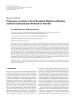
21.81.61.41.210.80.60.40.20
Antenna spacing (d/λ)
0
5
10
15
20
25
30
35
40
45
Gain (dB)
10 element ULA with element power pattern cos
m
(θ)
m
= 1
m
= 5
m
= 10
m
= 20
Isotropic
Figure 5: The antenna array gain as a function of antenna spacing
for 10 elements ULA with different element gains.
array (ULA), the normalized array factor can be expressed as
f
n
(φ, θ) =
sin
(N/2)(kd cos θ + β)
N sin
(1/2)(kd cos θ + β)
,(7)
where N, d,andβ are the number of antenna elements,
antenna spacing between two adjacent elements, and phase
shift, respectively. For omni-directional antenna, it can be
shown that up to 100 elements are required to achieve only
23 dBi gain w hich is far from the required specification
shown previously. Hence a more directive element is required
to improve the overall gain of the array. As shown in Figure 5,
to achieve a 40 dBi gain, 10 elements ULA w ith 16 dBi ele-
ment spaced around λ/2isrequired.
5. TECHNICAL CHALLENGES
Despite many advantages offered and high potentials appli-
cations envisaged in 60 GHz, there are number of technical
challenges and open issues that must be solved prior to the
successful deployment of this technology. These challenges
can be broadly classified into channel propagation issues, an-
tenna technology, RF solution, and choice of modulation.
Channel propagation
Although many channel measurements and modeling ef-
fort have been reported in the literature for various fre-
quency range such as the 5 GHz WLAN band [28–30]and
3–10 GHz UWB band [31–39], there are still lack of chan-
nel measurements and modeling effort for the frequency
range at 60 GHz. In general, the path loss at 60 GHz is sig-
nificantly higher than those at lower frequencies. This is
also true for tr a nsmission loss at 60 GHz for many materials
[23, 24, 40, 41]. The higher path loss and transmission loss at
60 GHz effectively limits the operation to one room. In order
to have wider coverage, relays or regenerative repeaters are
required. Furthermore, as described in Section 4, the use of
high gain antenna is necessary to compensate the high path
loss incurred, and the use of this single high gain antenna is
only feasible if clear LOS condition is always guaranteed. In
scenario where clear LOS is not guaranteed due to, for ex-
ample, a movement of human, the antenna arrays solution
becomes highly desirable. Unfortunately, there is no specific
channel model at 60 GHz that sufficiently addresses the spa-
tial properties and effect of human movement. Recent con-
tributions which measured the angle of arrival of the received
signal using antenna array [42] and rotational of directive an-
tenna [43] show that an angle spread of approximately 14
in corridor and desktop environment, respectively. However,
more measurements are required to further characterize and
validate these results.
Furthermore, all of the channel models available are radio
channel w hich are antenna dependent and are only valid for
the particular antenna setups used in the measurement. To
overcome this limitation, a propagation channel is required
which excludes the effects of antenna [44] and al lows the in-
vestigation of the effects of different type of antenna setups
with different gain/beamwidth on the 60 GHz system perfor-
mance. This is very important as measurements and ray trac-
ings have shown that the use of high gain antenna can signif-
icantly reduce the delay spread of the radio channel when the
Tx and Rx antennas are aligned [45].However,adetrimental
effect would be resulted for a slight pointing error of the main
lobe of the antenna off the direction of arrival of the signal
[46, 47]. In addition, measurements also demonstrated the
effects of multipath suppression using circular polarization
over linear polarization [48], but more extensive measure-
ments are needed to affirm these results and to what extent
this suppression occurs at 60 GHz.
Antenna technology
Many types of antenna st ructures are considered not suit-
able for 60 GHz WPAN/WLAN applications due to the re-
quirements for low cost, small size, light weight, and high
gain. In addition, 60 GHz antennas also require to be oper-
ated with approximately constant gain and high efficiency
over the broad frequency range (57–66 GHz). The impor-
tance of beamforming at 60 GHz has been discussed in
Section 4, which can be achieved by either switched beam
arrays or phase arrays. Switched beam arrays have multiple
fixed beams that can be selected to cover a given ser vice area.
It can be implemented much easier compared to the phase
arrays which required the capability of continuously varying
the progressive phase shift between the elements. The com-
plexity of phase arrays at 60 GHz typically limits the num-
ber of elements. In [49], a 2
2 beam steering antenna with
circular polarization at 61 GHz is developed. The gain is ap-
proximately 14 dBi with 20
HPBW. Similarly in [50], an-
other 60 GHz integrated 4-element planar array is developed
with average conversion loss of less that 10.6 dB for the four
8 EURASIP Journal on Wireless Communications and Networking
channels. The implementation of larger phase arr ay, how-
ever, presents some technical challenges such as requirement
for higher feed network loss, more complex phase control
network, stronger coupling between antennas as well as feed-
lines, and so forth. These challenges make the design and
fabricationofthelargerphasearraysbecomemorecomplex
and expensive. Hence, more research are required to develop
a low cost, small size, light weigh, and high gain steerable
antenna array that can be integrated into the RF front end
electronics.
Integrated circuit technology
The choice of integrated circuit (IC) technology depends on
the implementation aspects and system requirements. The
former is related to the issues such as power consumption,
efficiency, dynamic range, linearity requirements, integration
level, and so forth, while the later is related to the trans-
mission rate, cost and size, modulation scheme, transmit
power, bandwidth, and so forth. At mmWave, there are three
competing IC technologies, namely: (1) group III and IV
semiconductor technology such as Gallium Arsenide ( GaAs)
and Indium Phosphide (InP); (2) Silicon Germanium (SiGe)
technology such as HBT and BiCMOS; and (3) Silicon tech-
nology such as CMOS and BiCMOS. There is no single tech-
nology that can simultaneously meet all the objectives de-
fined in the technical challenges and system requirements.
For example, GaAs technology allows fast, high gain, and low
noise implementation but suffers poor integration and ex-
pensive implementation. On the other hand, SiGe technol-
ogy is a cheaper alternative to the GaAs with comparable per-
formance. In [51], the first mmWave fully antenna integrated
SiGe chip has been demonstrated.
Typically, as have been witnessed in the past, for broad
market exploitation and mass deployment, the size and cost
are the key factors that drive to the success of a particu-
lar technology. In this regard, CMOS technology appears to
be the leading candidate as it provides low-cost and high-
integration solutions compared to the others at the expense
of performance degradation such as low gain, linearity con-
straint, poor noise, lower transit frequency, and lower maxi-
mum oscillation frequency. Recent advances in CMOS tech-
nology [52] have demonstr a ted the feasibility of bulk CMOS
process at 130 nm for 60 GHz RF building blocks, active and
passive elements. More future research and investigations in
developing a fully integrated CMOS chip solution have to be
performed. Future technology should also aim at 90 nm and
65 nm CMOS processes in order to further improve the gain
and lower power consumption of the devices.
Modulation schemes
The choice of modulation schemes for 60 GHz radio will be
highly dependent on the propagation channel, the use of high
gain antenna/antenna array, and the limitations imposed by
the RF technology. For instance, if the delay spread of the
underlying propagation channel is high, then an orthogo-
nal frequency division multiplexing (OFDM) is an obvious
choice of modulation since OFDM can effectively turn the
frequency selective channel into flat fading channel by divid-
ing the high-rate stream into a set of parallel lower rate sub-
streams. This simplifies the equalization technique for multi
gigabit wireless system. On the other hand, high gain or cir-
cular polarized antenna systems can be used to significantly
reduce the effect of multipath and therefore will favor simple
modulation such as sing le carrier to save power consumption
and cost.
Typically, in CMOS circuit implementation, the 60 GHz
power amplifier has lower power and higher linearity re-
quirement. This implies that the use of simple modulation
than the OFDM system which suffers large peak-to-average
ratio (PAPR) and can greatly reduce the efficiency of the
power amplifier. Furthermore, the poor phase noise charac-
teristic of 60 GHz CMOS also restricts the use of higher order
modulation for quadrature amplitude modulation (QAM),
phase shift keying (PSK), and frequency shift keying (FSK)
to less than 16 QAM/16 PSK/16 FSK. The use of lower order
modulation is also motivated by the huge unlicensed band-
width available at 60 GHz. Hence, the choice of modulation
is clearly a tradeoff ofanumberofissueswhichneedtobe
well understood and characterized before a robust modula-
tion scheme can be sought.
6. CONCLUSION
In this paper, an overview of the 60 GHz technology is pre-
sented. The huge unlicensed bandwidth coupled with hig h er
allowable transmit power, smal l form factor, and advances
in integrated circuit technology have made 60 GHz a very
promising candidate for multigigabit applications. Intense
efforts are underway to expedite the commercialization of
this fascinating technology from standardization act ivities,
industrial alliances and regulatory bodies. A simple feasi-
bility study on wireless uncompressed video streaming on
HDTV using realistic parameters revealed the roles of an-
tenna in establishing a reliable 60 GHz communication link.
The importance of antenna system are to provide suffi-
cient power margin through array gain as well as to beam-
form the signal to other significant paths in case of hu-
man blockage of the main path. Despite the clear advan-
tages of 60 GHz system, a number of open issues and tech-
nical challenges have yet to be fully addressed. The propaga-
tion and implementation issues are the two aspects that re-
quire further optimization and research in order to obtain
atrulyefficient and low cost 60 GHz communication sys-
tem.
REFERENCES
[1] A. D. Oliver, “Millimeter wave systems - past, present and fu-
ture,” IEE Proceedings, vol. 136, no. 1, pp. 35–52, 1989.
[2] />[3] S. K. Yong, “Multi gigabit wireless through millimeter wave
in 60 GHz band,” in Proceedings of Wireless Conference Asia,
Singapore, November 2005.
[4] FCC, “First Report and Order,” February 2002, http://hraun-
foss.fcc.gov/edocs
public/.
S. K. Yong and C C. Chong 9
[5] C C. Chong, F. Watanabe, and H. Inamura, “Potential of
UWB technology for the next generation wireless communi-
cations,” in Proceedings of IEEE 9th International Symposium
on Spread Spectrum Techniques and Applications (ISSSTA ’06),
pp. 422–429, Manaus, Amazon, Brazil, August 2006.
[6] FCC, “Code of Federal Regulation, title 47 Telecommunica-
tion, chapter 1, part 15.255,” October 2004.
[7] Spectrum Management Telecommunications, “Radio Stan-
dard Specification-210, Issue 6, Low-Power Licensed-Exempt
Radio Communication Devices (All Frequency Bands): Cate-
gory 1 Equipment,” September 2005.
[8] Regulations for enforcement of the radio law 6-4-2 specified
low power radio station (11) 59-66GHz band.
[9] ACMA, “Radiocommunications (Low Interference Potential
Devices) Class License Variation 2005 (no. 1),” August 2005.
[10] Ministry of Information Communication of Korea, “Fre-
quency Allocation Comment of 60 GHz Band,” April 2006.
[11] ETSI DTR/ERM-RM-049, “Electromagnetic compatibility
and Radio spectrum Matters (ERM); System Reference Doc-
ument; Technical Characteristics of Multiple Gigabit Wireless
Systems in the 60 GHz Range,” March 2006.
[12] Korean Frequency Policy & Technology Workshop, Session 7,pp.
13–32, November 2005.
[13] CEPT Recommendation T/R 22-03, “Provisional recom-
mended use of the frequency range 54.25-66 GHz by ter-
restrial fixed and mobile systems,” in Proceedings of Euro-
pean Postal and Telecommunications Administration Collection
(CEPT ’90), pp. 1–3, Athens, Greece, January 1990, http://
www.ero.dk/documentation/.
[14] ERC Recommendation 12-09, “Radio Frequency Channel Ar-
rangement for Fixed Service Systems Operating in the Band
57.0 - 59.0 GHz Which Do Not Require Frequency Planning,
The Hague 1998 revised Stockholm,” October 2004.
[15] ECC Recommendation (05)02, “Use of the 64-66 GHz Fre-
quency Band for Fixed Services,” June 2005.
[16] IEEE Standard 802.16 2001, “IEEE Standard for Local and
Metropolitan Area Networks—Part 16 - Air Interface for Fixed
Broadband Wireless Access Systems,” 2001.
[17] ARIB STD-T69, “Millimeter-Wave Video Transmission
Equipment for Specified Low Power Radio Station,” July 2004.
[18] ARIB STD-T69, “Millimeter-Wave Data Tr ansmission Equip-
ment for Specified Low Power Radio Station (Ultra High
Speed Wireless LAN System),” May 2001.
[19] R. Roberts, “WiMedia 60 GHz Study Group,” IEEE 802.15-05-
0248-00-003c, Jacksonville, Fla, USA, May 2006.
[20] A. Sadri, “802.15.3c Usage Model Document,” IEEE 802.15-
06-0055-14-003c, Jacksonville, Fla, USA, May 2006.
[21] S. K. Yong, “TG3c Channel Modeling Sub-Committee Final
Report (Draft),” IEEE 802.15-06-0195-02-003c, Jacksonville,
Fla, USA, May 2006.
[22] M. K. Simon and M. S. Alouini, Digital Communication over
Fading Channels, Wiley-IEEE Press, New York, NY, USA,
2nd edition, 2004.
[23] M. Fiacoo and S. Saunders, “Final report for OFCOM - indoor
propagation factors at 17 GHz and 60 GHz,” August 1998.
[24] C. R. Anderson and T. S. Rappaport, “In-building wideband
partition loss measurements at 2.5 and 60 GHz,” IEEE Trans-
actions on Wireless Communications, vol. 3, no. 3, pp. 922–928,
2004.
[25] S. Collonge, G. Zaharia, and G. E. Zein, “Influence of the hu-
man activ ity on wide-band characteristics of the 60 GHz in-
door radio channel,” IEEE Transactions on Wireless Communi-
cations, vol. 3, no. 6, pp. 2396–2406, 2004.
[26] P. F. M. Smulders, Broadband wireless LANs: a feasibility study,
Ph.D. thesis, Eindhoven University of Technology, Eindhoven,
The Netherlands, 1995.
[27] C. A. Balanis, Antenna Theory: Analysis and Design,JohnWiley
& Sons, New York, NY, USA, 2nd edition, 1997.
[28] C C. Chong, C M. Tan, D. I. Laurenson, S. McLaughlin, M.
A. Beach, and A. R. Nix, “A new statistical wideband spatio-
temporal channel model for 5-GHz band WLAN systems,”
IEEE Journal on Selected Areas in Communications, vol. 21,
no. 2, pp. 139–150, 2003.
[29] C C. Chong, D. I. Laurenson, and S. McLaughlin, “Spatio-
temporal correlation properties for the 5.2-GHz indoor prop-
agation environments,” IEEE Antennas and Wireless Propaga-
tion Letters, vol. 2, no. 1, pp. 114–117, 2003.
[30] C C. Chong, C M. Tan, D. I. Laurenson, S. McLaughlin, and
M. A. Beach, “A novel wideband dynamic directional indoor
channelmodelbasedonaMarkovprocess,”IEEE Transac-
tions on Wireless Communications, vol. 4, no. 4, pp. 1539–1552,
2005.
[31] M. Z. Win and R. A. Scholtz, “On the robustness of ultra-wide
bandwidth signals in dense multipath environments,”
IEEE
Communications Letters, vol. 2, no. 2, pp. 51–53, 1998.
[32] M. Z. Win and R. A. Scholtz, “On the energy capture of ult ra-
wide bandwidth signals in dense multipath environments,”
IEEE Communication Letters, vol. 2, no. 9, pp. 245–247, 1998.
[33] R.J.Cramer,R.A.Scholtz,andM.Z.Win,“Anevaluationof
the ultra-wideband propagation channel,” IEEE Transactions
on Antennas and Propagation, vol. 50, no. 5, pp. 561–570, 2002.
[34] D. Cassioli, M. Z. Win, and A. F. Molisch, “The ultra-wide
bandwidth indoor channel: from statistical model to simu-
lations,” IEEE Journal on Selected Areas in Communications,
vol. 20, no. 6, pp. 1247–1257, 2002.
[35] M. Z. Win and R. A. Scholtz, “Characterization of ultra-
wide bandwidth wireless indoor channels: a communication-
theoretic view,” IEEE Journal on Selected Areas in Communica-
tions, vol. 20, no. 9, pp. 1613–1627, 2002.
[36] C C. Chong and S. K. Yong, “A generic statistical-based UWB
channel model for high-rise apartments,” IEEE Transactions on
Antennas and Propagation, vol. 53, no. 8, pp. 2389–2399, 2005.
[37] C C. Chong, Y E. Kim, S. K. Yong, and S S. Lee, “Statistical
characterization of the UWB propagation channel in indoor
residential environment,” Wireless Communications and Mo-
bile Computing, vol. 5, no. 5, pp. 503–512, 2005.
[38] C C. Chong, “UWB channel modeling and impact of wide-
band channel on system design,” in UWB Wireless Communi-
cations,H.ArslanandZ.N.Chen,Eds.,chapter8,JohnWiley
& Sons, New York, NY, USA, 2006.
[39] A. F. Molisch, D. Cassioli, C C. Chong, et al., “A comprehen-
sive standardized model for ultrawideband propagation chan-
nels,” IEEE Transactions on Antennas and Propagation, vol. 54,
no. 11, pp. 3151–3166, 2006.
[40] E. J. Violette, R. H. Espeland, R. O. DeBolt, and F. K. Schw-
ering, “Millimeter-wave propagation at street level in an ur-
ban environment,” IEEE Transactions on Geoscience and Re-
mote Sensing, vol. 26, no. 3, pp. 368–380, 1988.
[41] B. Langen, G. Lober, and W. Herzig, “Reflection and transmis-
sion behaviour of building materials at 60GHz,” in Proceedings
of the 5th IEEE International Symposium on Personal, Indoor
and Mobile Radio Communications (PIMRC ’94), vol. 2, pp.
505–509, The Hague, Netherlands, September 1994.
[42] M S. Choi, G. Grosskopf, and D. Rohde, “Statistical charac-
teristics of 60 GHz wideband indoor propagation channel,” in
Proceedings of the 16th International Symposium on Personal,
10 EURASIP Journal on Wireless Communications and Networking
Indoor and Mobile Radio Communications (PIMRC ’05), vol. 1,
pp. 599–603, Berlin, Germany, September 2005.
[43] C. S. Liu, et al., “NICTA Indoor 60 GHz Channel Measure-
ments and Analysis update,” IEEE 802.15-06-222-00-003c,
Jacksonville, Fla, May 2006.
[44] M. Steinbauer, A. F. Molisch, and E. Bonek, “The double-
directional radio channel,” IEEE Antennas and Propagation
Magazine, vol. 43, no. 4, pp. 51–63, 2001.
[45]H.Yang,P.F.M.Smulders,andM.H.A.J.Herben,“Fre-
quency selectivity of 60 GHz LOS and NLOS indoor radio
channels,” in Proceedings of IEEE Vehicular Technology Confer-
ence (VTC ’06), Melbourne, Australia, May 2006.
[46]M.R.Williamson,G.E.Athanasiadou,andA.R.Nix,“In-
vestigating the effects of antenna directivity on wireless in-
door communication at 60GHz,” in Proceedings of IEEE In-
ternational Symposium on Personal, Indoor and Mobile Radio
Communications (PIMRC ’97), vol. 2, pp. 635–639, Helsinki,
Finland, September 1997.
[47] T. Manabe, Y. Miura, and T. Ihar a, “Effects of antenna direc-
tivity and polarization on indoor multipath propagation char-
acteristics at 60 GHz,” IEEE Journal on Selected Areas in Com-
munications, vol. 14, no. 3, pp. 441–448, 1996.
[48] T. Manabe, K. Sato, H. Masuzawa, et al., “Polarization depen-
dence of multipath propagation and high-speed transmission
characteristics of indoor millimeter-wave channel at 60 GHz,”
IEEE Transactions on Vehicular Technology,vol.44,no.2,pp.
268–274, 1995.
[49] K C. Huang and Z. Wang, “Millimeter-wave circular polar-
ized beam-steering antenna array for gigabit wireless com-
munications,” IEEE Transactions on Antennas and Propagation,
vol. 54, no. 2, part 2, pp. 743–746, 2006.
[50] J Y. Park, Y. Wang, and T. Itoh, “A 60 GHz integrated an-
tenna array for high-speed digital beamforming applications,”
in Proceedings of IEEE MTT-S International Microwave Sympo-
sium Digest, vol. 3, pp. 1677–1680, Philadelphia, Pa, USA, June
2003.
[51] B. Gaucher, “Completely Integrated 60 GHz ISM Band Front
End Chip Set and Test Results,” IEEE 802.15-15-06-0003-00-
003c, Big Island, Hawaii, USA, January 2006.
[52] C.H.Doan,S.Emami,A.M.Niknejad,andR.W.Broderson,
“Millimeter-wave CMOS design,” IEEE Journal of Solid-State
Circuits, vol. 40, no. 1, pp. 144–155, 2005.