Báo cáo hóa học: " Research Article Radar Sensor Networks: Algorithms for Waveform Design and Diversity with Application to ATR with Delay-Doppler Uncertainty" pot
Bạn đang xem bản rút gọn của tài liệu. Xem và tải ngay bản đầy đủ của tài liệu tại đây (662.41 KB, 9 trang )
Hindawi Publishing Corporation
EURASIP Journal on Wireless Communications and Networking
Volume 2007, Article ID 89103, 9 pages
doi:10.1155/2007/89103
Research Article
Radar Sensor Networks: Algorithms for Waveform
Design and Diversity with Application to ATR with
Delay-Doppler Uncertainty
Qilian Liang
Department of Electrical Engineering, University of Texas at Arlington, Room 518, 416 Yates Street, Arlington,
TX 76019-0016, USA
Received 30 May 2006; Revised 28 November 2006; Accepted 29 November 2006
Recommended by Xiuzhen Cheng
Automatic target recognition (ATR) in target search phase is very challenging because the target range and mobility are not yet
perfectly known, which results in delay-Doppler uncertainty. In this paper, we firstly perform some theoretical studies on radar
sensor network (RSN) design based on linear frequency modulation (LFM) waveform: (1) the conditions for waveform coexis-
tence, (2) interferences among waveforms in RSN, (3) waveform diversity in RSN. Then we apply RSN to ATR with delay-Doppler
uncertainty and propose maximum-likeihood (ML) ATR algorithms for fluctuating targets and nonfluctuating targets. Simulation
results show that our RSN vastly reduces the ATR error compared to a single radar system in ATR with delay-Doppler uncertainty.
The proposed waveform design and diversity algorithms can also be applied to active RFID sensor networks and underwater acous-
tic sensor networks.
Copyright © 2007 Qilian Liang. This is an open access article distributed under the Creative Commons Attribution License, which
permits unrestricted use, distribution, and reproduction in any medium, provided the original work is properly cited.
1. INTRODUCTION AND MOTIVATION
The goal for any target recognition system is to give the most
accurate interpretation of what a target is at any given point
in time. There are two classes of motion models of targets,
one for maneuvering targets and one for nonmaneuvering
(constant velocity and acceleration) targets. The area that is
still lacking in target recognition is the ability to detect reli-
ably when a target is beginning a maneuver where its speed
and range are uncertain. The tracking system can switch the
algorithms applied to the problem from a nonmaneuvering
set to the maneuvering set when a target is beginning a ma-
neuver. But when the tracker does finally catch up to the tar-
get after the maneuver and then perform ATR, the latency is
too high. In time-critical mission situation, such latency in
ATR is not tolerable. In this paper, we are interested in study-
ing automatic target recognition with range and speed uncer-
tainty, that is, delay-Doppler uncertainty, using radar sensor
networks (RSN). The network of radar sensors should oper-
ate with multiple goa ls managed by an intelligent platform
network that can manage the dynamics of each radar to meet
the common goals of the platform rather than each radar to
operate as an independent system. Therefore, it is significant
to perform signal design and processing and networking co-
operatively within and between platforms of radar sensors
and their communication modules. In this paper, we are
interested in studying algorithms on radar sensor network
(RSN) design based on linear frequency modulation (LFM)
waveform: (1) the conditions for waveform coexistence, (2)
interferences among waveforms in RSN, (3) waveform diver-
sity in RSN. Then we apply RSN to automatic target recogni-
tion (ATR) with delay-Doppler uncertainty.
In nature, diverse waveforms are transmitted by animals
for specific applications. For example, when a bat and a whale
are in the search mode for food, they emit a different type
of waveform than when they are trying to locate their prey.
The Doppler-invariant waveforms that they t ransmit are en-
vironment dependent [1]. Hence, in RSN, it may be useful to
transmit different waveforms from different neighbor radars
and they can collaboratively perform waveforms diversity for
ATR. Sowelam and Tewfik [2] developed a signal selection
strategy for radar target classification, and a sequential clas-
sification procedure was proposed to minimize the average
number of necessary signal transmissions. Intelligent wave-
form selection was studied in [3, 4], but the effect of Doppler
shift was not considered. In [5], the performance of constant
2 EURASIP Journal on Wireless Communications and Networking
frequency (CF) and LFM waveform fusion from the stand-
point of the whole system was studied, but the effects of clut-
ter were not considered. In [6], CF and LFM waveforms were
studied for sonar system, but it was assumed that the sensor is
nonintelligent (i.e., waveform cannot be selected adaptively).
All the above studies and design methods were focused on
the waveform design or selection for a single active radar or
sensor. In [7], cross-correlation properties of two radars are
briefly mentioned and the binary coded pulses using sim-
ulated annealing [8] are highlighted. However, the cross-
correlation of two binary sequences such as binary coded
pulses (e.g., Barker sequence) are much easier to study than
that of two analog radar waveforms. In [9], CF waveform de-
sign was applied to RSN with application to ATR without
any delay-Doppler uncertainty. In this paper, we will focus
on the waveform design fusion for radar sensor networks us-
ing LFM waveform.
The rest of this paper is organized as follows. In Section 2,
we study the coexistence of LFM r adar waveforms. In Sec-
tion 3, we analyze the interferences among LFM radar wave-
forms. In Section 4,weproposeaRAKEstructureforwave-
form diversity combining and propose maximum-likelihood
(ML) algorithms for ATR with delay-Doppler uncertainty.
In Section 5, we provide simulation results on ML-ATR with
delay-Doppler uncertainty. In Section 6,weconcludethispa-
per and provide some future works.
2. COEXISTENCE OF LFM RADAR WAVEFORMS
In RSN, radar sensors will interfere with each other and the
signal-to-interference-ratio may be very low if the waveforms
are not properly designed. We will introduce orthogonality
as one criterion for waveforms design in RSN to make them
coexistence. Besides, the radar channel is narrowband, so we
will also consider the bandwidth constraint.
In our radar sensor networks, we choose LFM waveform.
The LFM waveform can be defined as
x( t)
=
E
T
exp
j2πβt
2
, −
T
2
≤ t ≤
T
2
. (1)
In radar, ambiguity function (AF) is an analytical tool for
waveform design and analysis that succinctly characterizes
the behavior of a waveform paired with its matched filter. The
ambiguity function is useful for examining resolution, side
lobe behavior, and ambiguities in both range and Doppler
for a given waveform [10]. For a single radar, the matched
filter for waveform x(t)isx
∗
(−t), and the ambiguity func-
tion of LFM waveform is [10]
A
τ, F
D
=
T/2
−T/2+τ
x( t)exp
j2πF
D
t
x
∗
(t − τ)dt
=
E sin
π
F
D
+ βτ
T −|τ|
Tπ
F
D
+ βτ
, −T ≤ τ ≤ T.
(2)
Three special cases can simplify this AF:
(1) when τ
= 0,
A
0, F
D
=
E sin
πF
D
T
Tπ
F
D
;(3)
(2) when F
D
= 0,
A(τ,0)
=
E sin
πβτ
T −|τ|
Tπβτ
, −T ≤ τ ≤ T;
(4)
(3) and
A(0, 0)
= E. (5)
However, the above ambiguity is for one radar only (no co-
existing radar).
For radar sensor networks, the waveforms from different
radars will interfere with each other. We choose the waveform
for radar i as
x
i
(t) =
E
T
exp
j2π
βt
2
+ δ
i
t
, −
T
2
≤ t ≤
T
2
(6)
which means there is a frequency shift δ
i
for radar i. To min-
imize the interference from one waveform to the other, opti-
mal values for δ
i
should be determined to have the waveforms
orthogonal to each other, that is, let the cross-correlation be-
tween x
i
(t)andx
n
(t)be0,
T/2
−T/2
x
i
(t)x
∗
n
(t)dt
=
E
T
T/2
−T/2
exp
j2π
βt
2
+ δ
i
t
exp
−
j2π
βt
2
+ δ
n
t
dt
= E sinc
π
δ
i
− δ
n
T
.
(7)
If we choose
δ
i
=
i
T
,(8)
where i is a dummy index, then (7) can have two cases:
T/2
−T/2
x
i
(t)x
∗
n
(t)dt =
⎧
⎪
⎨
⎪
⎩
E, i = n,
0, i
= n.
(9)
So, choosing δ
i
= i/T in (6) can have orthogonal waveforms,
that is, the waveforms can coexist if the carrier spacing is
1/T between two radar waveforms. That is, orthogonality
amongst carriers can be achieved by separating the carriers
by an integer multiple of the inverse of waveform pulse du-
ration. With this design, all the orthogonal waveforms can
work simultaneously. However, there may exist time delay
and Doppler shift ambiguity which will have interferences to
other waveforms in RSN.
Qilian Liang 3
3. INTERFERENCES OF LFM WAVEFORMS IN
RADAR SENSOR NETWORKS
3.1. RSN with two radar sensors
We are interested in analyzing the interference from one
radar to another if there exist time delay and Doppler shift.
For a simple case where there are two radar sensors (i and n),
the ambiguity function of radar i (considering interference
from radar n)is
A
i
t
i
, t
n
, F
D
i
, F
D
n
(10)
=
∞
−∞
x
i
(t)exp
j2πF
D
i
t
+ x
n
t−t
n
exp
j2πF
D
n
t
x
∗
i
t − t
i
dt
(11)
≤
T/2+min(t
i
,t
n
)
−T/2+max(t
i
,t
n
)
x
n
t−t
n
exp
j2πF
D
n
t
x
∗
i
t−t
i
dt
+
T/2
−T/2+t
i
x
i
(t)exp
j2πF
D
i
t
x
∗
i
t − t
i
dt
(12)
=
T/2+min(t
i
,t
n
)
−T/2+max(t
i
,t
n
)
x
n
t−t
n
exp
j2πF
D
n
t
x
∗
i
t−t
i
dt
+
E sin
π
F
D
i
+ βt
i
T −
t
i
Tπ
F
D
i
+ βt
i
.
(13)
To make analysis easier, we assume t
i
= t
n
= τ which is
a reasonable assumption because radar sensors can b e co-
ordinated by the clusterhead to send out LFM waveforms.
Then (13) can be simplified as
A
i
τ, F
D
i
, F
D
n
≈
E sinc
π
n − i + F
D
n
T
+
E sin
π
F
D
i
+ βτ
T −|τ|
Tπ
F
D
i
+ βτ
.
(14)
Some special cases of (14) are listed as follows.
(1) If F
D
i
= F
D
n
= 0, then (14)becomes
A
i
(τ,0,0)≈
E sin
πβτ
T −|τ|
πβTτ
. (15)
(2) If τ
= 0, then (14)becomes
A
i
0, F
D
i
, F
D
n
≈
E sinc
π
n − i + F
D
n
T
+
E sinc
πF
D
i
T
.
(16)
(3) If F
D
i
= F
D
n
= 0, τ = 0, and δ
i
and δ
n
follow (8), then
(14)becomes
A
i
(0,0,0) ≈ E. (17)
3.2. RSN with M radar sensors
ItcanbeextendedtoanRSNwithM radars. Assuming time
delay τ for each radar is the same, then the ambiguity func-
tion of radar 1 (considering interferences from all the other
M
− 1 radars with CF pulse waveforms) can be expressed as
A
1
τ, F
D
1
, , F
D
M
≈
M
i=2
E sinc
π
i − 1+F
D
i
T
+
E sin
π
F
D
1
+ βτ
T −|τ|
Tπ
F
D
1
+ βτ
.
(18)
Similarly, we can have three special cases.
(1) If F
D
1
= F
D
2
=···= F
D
M
= 0, then (18)becomes
A
1
(τ,0,0, ,0)≈
E sin
πβτ
T −|τ|
πβTτ
. (19)
Comparing it against (4), it shows that our derived condition
in (6) can have a radar in RSN and it gets the same signal
strength as that of a single radar (no coexisting radar) when
the Doppler shift is 0.
(2) If τ
= 0, then (18)becomes
A
1
0, F
D
1
, F
D
2
, , F
D
M
≈
M
i=1
E sinc
π
i − 1+F
D
i
T + βτT
.
(20)
Comparing to (3), a radar in RSN has more interferences
when unknown Doppler shifts exist.
(3) If F
D
1
= F
D
2
= ··· = F
D
M
= 0, τ = 0, and δ
i
in (6)
follows (8), then (18)becomes
A
1
(0,0,0, ,0)≈ E. (21)
4. APPLICATION TO ATR WITH DELAY-DOPPLER
UNCERTAINTY
In RSN, the radar sensors are networked together in an ad
hoc fashion. They do not rely on a pre-existing fixed infras-
tructure, such as a wireline backbone network or a base sta-
tion. They are self-organizing entities that are deployed on
demand in support of various events surveillance, battlefield,
disaster relief, search and rescue, and so forth. Scalability
concern suggests a hierarchical organization of radar sensor
networks with the lowest level in the hierarchy being a clus-
ter. As argued in [11–14], in addition to helping with scala-
bility and robustness, aggregating sensor nodes into clusters
has additional benefits:
(1) conserving radio resources such as bandwidth;
(2) promoting spatial code reuse and frequency reuse;
(3) simplifying the topology, for example, when a mobile
radar changes its location, it is sufficient for only the
nodes in attended clusters to u pdate their topology in-
formation;
4 EURASIP Journal on Wireless Communications and Networking
(4) reducing the generation and propagation of routing
information; and,
(5) concealing the details of global network topology from
individual nodes.
In RSN, each radar can provide their waveform parameters
such as δ
i
to their clusterhead radar, and the clusterhead
radar can combine the waveforms from its cluster members.
In RSN with M r adars, the received signal for clusterhead
(assume it is radar 1) is
r
1
(u, t) =
M
i=1
α(u)x
i
t − t
i
exp
j2πF
D
i
t
+ n(u, t), (22)
where α(u) stands for radar cross section (RCS) and can be
modeled using nonzero constants for nonfluctuating target
and four Swerling target models for fluctuating target [10];
F
D
i
is the Doppler shift of target relative to waveform i; t
i
is
delay of waveform i,andn(u, t) is additive white Gaussian
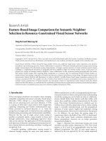
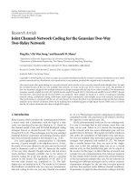
noise (AWGN). In this paper, we propose a RAKE structure
for waveform diversity combining, as illustrated by Figure 1.
According to this structure, the received r
1
(u, t)ispro-
cessed by a bank of matched filters, then the output of branch
1 (after integration) is
Z
1
u; t
1
, , t
M
, F
D
1
, , F
D
M
=
T/2
−T/2
r
1
(u, t)x
∗
1
t − t
1
ds
=
T/2
−T/2
M
i=1
α(u)x
i
t − t
i
exp
j2πF
D
i
t
+ n(u, t)
×
x
∗
1
t − t
1
dt
,
(23)
where
T/2
−T/2
n(u, t)x
∗
1
(t − t
1
)dt can easily be proved to be
AWGN, let
n
u, t
1
T/2
−T/2
n(u, t)x
∗
1
t − t
1
dt (24)
follow a white Gaussian distribution. Assuming t
1
= t
2
=
···=
t
M
= τ, then based on (18),
Z
1
u; τ, F
D
1
, , F
D
M
≈
M
i=2
α(u)E sinc
π
i − 1+F
D
i
T
+
α(u)E sin
π
F
D
1
+ βτ
T −|τ|
Tπ
F
D
1
+ βτ
+ n(u, τ)
.
(25)
r
1
(u, t)
x
x
x
x
1
(t t
1
)
x
2
(t t
2
)
x
M
(t t
M
)
.
.
.
.
.
.
T
()dt
T
()dt
T
()dt
Z
1
Z
2
Z
M
Diversity
combining
Figure 1: Waveform diversity combining by clusterhead in RSN.
Similarly, we can get the output for any branch m (m =
1, 2, , M),
Z
m
u; τ, F
D
1
, , F
D
M
≈
M
i=1, i=m
α(u)E sinc
π
i − m + F
D
i
T
+
α(u)E sin
π
F
D
m
+ βτ
T −|τ|
Tπ
F
D
m
+ βτ
+ n(u, τ)
.
(26)
So,
|Z
m
(u; τ, F
D
1
, , F
D
M
)| consists of three parts, signal (re-
flected signal from radar m waveform):
α(u)E sin
π
F
D
m
+ βτ
T −|τ|
Tπ
F
D
m
+ βτ
, (27)
interferences from other waveforms:
M
i=1, i=m
α(u)E sinc
π
i − m + F
D
i
T
, (28)
and noise:
|n(u, τ)|. Delay-Doppler uncertainty happens
quite often in target search and recognition where target
range and velocity are not yet perfectly known.
We can also have three special cases for
Z
m
u; τ, F
D
1
, , F
D
M
. (29)
(1) When F
D
1
=··· =F
D
M
= 0,
Z
m
(u; τ,0,0, ,0)
≈
α(u)E sin
πβτ
T −|τ|
Tπβτ
+ n(u, τ)
.
(30)
(2) If τ
= 0, then (26)becomes
Z
m
u;0,F
D
1
, , F
D
M
≈
M
i=1
α(u)E sinc
π
i − m + F
D
i
T
+ n(u)
.
(31)
(3) If τ
= 0andF
D
1
=···= F
D
M
= 0, then (26)becomes
Z
m
(u;0,0,0, ,0)
≈
Eα(u)+n(u)
. (32)
Qilian Liang 5
How to combine all the Z
m
’s (m = 1, 2, , M)isvery
similar to the diversity combining in communications to
combat channel fading, and the combination schemes may
be different for different applications. In this paper, we are
interested in applying RSN waveform diversity to ATR, for
example, recognition that the echo on a radar display is that
of an aircraft, ship, motor vehicle, bird, person, rain, chaff,
clear-air turbulence, land clutter, sea clutter, bare mountains,
forested areas, meteors, aurora, ionized media, or other nat-
ural phenomena. Early radars were “blob” detectors in that
they detected the presence of a target and gave its location
in range and angle, and radar began to be more than a blob
detector and could provide recognition of one type of tar-
get from another [7]. It is known that small changes in the
aspect angle of complex (multiple scatter) targets can cause
major changes in the radar cross section ( RCS). This has been
considered in the past as a means of target recognition, and is
called fluctuat ion of radar c ross section with aspect angle,but
it has not had much success [7]. In this paper, we propose
a maximum-likelihood automatic target recognition (ML-
ATR) algorithm for RSN. We will study both fluctuating tar-
gets and nonfluctuating targets.
4.1. ML-ATR for fluctuating targets with
delay-Doppler uncertainty
Fluctuating target modeling is more realistic in which the
target RCS is drawn from either the Rayleigh or chi-square
of degree four pdf. The Rayleigh model describes the be-
havior of a complex target consisting of many scatters, none
of which is dominant. The fourth-degree chi-square mod-
els targets having many scatters of similar strength with one
dominant scatter. Based on different combinations of pdf
and decorrelation characteristics (scan-to-scan or pulse-to-
pulse decorrelation), four Swerling models are used [10].
In this paper, we will focus on “Swerling 2” model which
is Rayleigh distribution with pulse-to-pulse decorrelation.
The pulse-to-pulse decorrelation implies that each individ-
ual pulse results in an independent value for RCS α.
For Swerling 2 model, the RCS
|α(u)| follows Rayleigh
distribution a nd its I and Q subchannels follow zero-mean
Gaussian distributions with variance γ
2
. Assume
α(u)
= α
I
(u)+ jα
Q
(u) (33)
and n(u)
= n
I
(u)+ jn
Q
(u) follows zero-mean complex Gau-
sian distribution with variance σ
2
for the I and Q subchan-
nels. Observe (26), for given τ, F
D
i
(i = 1, , M),
M
i=1, i=m
α(u)E sinc
π
i − m + F
D
i
T
+
α(u)E sin
π
F
D
m
+ βτ
T −|τ|
Tπ
F
D
m
+ βτ
=
α(u)E
M
i=1, i=m
sinc
π
i − m + F
D
i
T
+
sin
π
F
D
m
+ βτ
T −|τ|
Tπ
F
D
m
+ βτ
(34)
follows zero-mean complex Gaussian distributions with vari-
ance E
2
γ
2
[
M
i
=1, i=m
sinc[π(i − m + F
D
i
T)] + sin[π(F
D
m
+
βτ)(T
−|τ|)]/Tπ(F
D
m
+ βτ)]
2
for the I and Q subchannels.
Since n(u, τ) also follows zero-mean Gaussian distribution,
so
|Z
m
(u; τ, F
D
1
, , F
D
M
)| of (26) follows Rayleigh distribu-
tion. In real world, the perfect values of τ and F
D
i
are not
known in the target search phase and the mean values of
τ and F
D
i
are 0, so we just assume the parameter of this
Rayleigh distribution b
=
E
2
γ
2
+ σ
2
(when τ and F
D
i
equal
to 0).
Let y
m
|Z
m
(u; τ, F
D
1
, , F
D
M
)|, then
f
y
m
=
y
m
E
2
γ
2
+ σ
2
exp
−
y
2
m
2
E
2
γ
2
+ σ
2
. (35)
The mean value of y
m
is
π(E
2
γ
2
+ σ
2
)/2 and the variance is
(4
− π)(E
2
γ
2
+ σ
2
)/2. The variance of signal is (4 − π)E
2
γ
2
/2
and the variance of noise is (4
− π)σ
2
/2.
Let y [y
1
, y
2
, , y
M
], then the pdf of y is
f (y)
=
M
m=1
f
y
m
. (36)
Our ATR is a multiple-category hypothesis testing prob-
lem, that is, to decide a target category (e.g., different aircraft,
motor vehicle, etc.) based on r
1
(u, t). Assume there are to-
tally N categories and category n target has RCS α
n
(u)(with
variance γ
2
n
), so the ML-ATR algorithm to decide a target cat-
egory C can be expressed as
C
= arg max
n=1, ,N
f
y | γ = γ
n
=
arg max
n=1, ,N
M
m=1
y
m
E
2
γ
2
n
+ σ
2
exp
−
y
2
m
2
E
2
γ
2
n
+ σ
2
.
(37)
4.2. ML-ATR for nonfluctuating targets with
delay-Doppler uncertainty
In some sources, the nonfluctuating target is identified as
“Swerling 0” or “Swerling 5” model [15]. For nonfluctuat-
ing target, the RCS α(u) is just a constant α for a given target.
Observe (26), for given τ, F
D
i
(i = 1, , M),
M
i=1, i=m
α(u)E sinc
π
i − m + F
D
i
T
+
α(u)E sin
π
F
D
m
+ βτ
T −|τ|
Tπ
F
D
m
+ βτ
=
αE
M
i=1, i=m
sinc
π
i − m + F
D
i
T
+
sin
π
F
D
m
+ βτ
T −|τ|
Tπ
F
D
m
+ βτ
(38)
is just a constant. Since n(u, τ) follows zero-mean Gaus-
sian distribution, so
|Z
m
(u; τ, F
D
1
, , F
D
M
)| of (26)follows
6 EURASIP Journal on Wireless Communications and Networking
Table 1: RCS values at microwave frequency for 6 targets.
Index n Tar ge t RC S
1 Small single-engine aircraft 1
2
Large flighter aircraft 6
3
Medium bomber or jet airliner 20
4
Large bomber or jet airliner 40
5
Jumbo jet 100
6
Pickup truck 200
Rician distribution with direct path value
λ
= αE
M
i=1, i=m
sinc
π
i − m + F
D
i
T
+
sin
π
F
D
m
+ βτ
T −|τ|
Tπ
F
D
m
+ βτ
.
(39)
Since τ and F
D
i
are u ncertain and zero-mean, so we just use
the approximation
λ
= αE (40)
which is obtained when τ and F
D
i
equal to 0.
Let y
m
|Z
m
(u; τ, F
D
1
, , F
D
M
)|, then the probability
density function (pdf) of y
m
is
f
y
m
=
2y
m
σ
2
exp
−
y
2
m
+ λ
2
σ
2
I
0
2λy
m
σ
2
, (41)
where σ
2
is the noise power (with I and Q subchannel power
σ
2
/2), and I
0
(·) is the zero-order modified Bessel function of
the first kind. Let y [y
1
, y
2
, , y
M
], then the pdf of y is
f (y)
=
M
m=1
f
y
m
. (42)
The ML-ATR algorithm to decide a target category C
based on y can be expressed as,
C
= arg max
n=1, ,N
f
y | λ = E
α
n
=
arg max
n=1, ,N
M
m=1
2y
m
σ
2
× exp
−
y
2
m
+ E
2
α
2
n
σ
2
I
0
2E
α
n
y
m
σ
2
.
(43)
5. SIMULATIONS
Radarsensornetworkswillberequiredtodetectabroad
range of target classes. In this paper, we applied our ML-
ATR to automatic target recognition with delay-Doppler
uncertainty. We assume that the domain of target classes is
known a priori (N in Sections 4.1 and 4.2), and that the RSN
is confined to work only on the known domain.
For fluctuating target recognition, our targets have 6
classes with different RCS values, which are summarized
in Table 1 [7]. We assume the fluctuating targets follow
“Swerling 2” model (Rayleigh with pulse-to-pulse decorrela-
tion), and assume the RCS value listed in Tab le 1 to be the
standard deviation (std) γ
n
of RCS α
n
(u)fortargetn.We
applied the ML-ATR algorithm in Section 4.1 (for fluctuat-
ing target case) for target recognition within the six targets
domain. We chose T
= 0.1ms and β = 10
6
.Ateachav-
erage SNR value, we ran Monte-Carlo simulations for 10
5
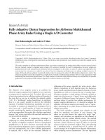
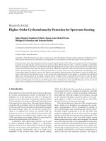
times for each target. In Figures 2(a), 2(b), 2(c), we plot
the average ATR error for fluctuating targets with different
delay-Doppler uncertainty and compared the performances
of single-radar system, 5-radar RSN, and 10-radar RSN. Ob-
serve these three figures.
(1) The two RSNs vastly reduce the ATR error com-
paring to a single-radar system in ATR with delay-Doppler
uncertainty, for example, the 10-radar RSN can a chieve ATR
error 2% comparing against the single-radar system with
ATR error 37% at SNR
= 32 dB with delay-Doppler uncer-
tainty τ
∈ [−0.1T,0.1T]andF
D
i
∈ [−200 Hz, 200 Hz].
(2) Our LFM waveform design can tolerate reasonable
delay-Doppler uncertainty which are testified by Figures
2(b), 2(c).
(3) According to Skolnik [7], radar performance with
probability of recognition error (p
e
) less than 10% is good
enough. Our 10-radar RSN with waveform diversity can have
probability of ATR error much less than 10% for the aver-
age ATR for all targets. However, the single-radar system has
probability of ATR error much higher than 10%. Our RSN
with waveform diversity is very promising to be used for real-
world ATR.
(4) Observe Figures 2(a), 2(c), the average probability of
ATR error in Figure 2(c) is not as sensitive to the SNR as
that in Figure 2(a), that is, ATR error curve slope becomes
flat with higher delay-Doppler uncertainty, which means that
the delay-Doppler uncertainty can dominate the ATR perfor-
mance when it is too high.
For nonfluctuating target recognition, our targets have
6 classes with different RCS values, which are summa-
rizedinTable1[7]. We applied the ML-ATR algorithms
in Section 4.2 (for nonfluctuating target case) to classify an
unknown target as one of these 6 target classes. We chose
T
= 0.1ms and β = 10
6
.AteachaverageSNRvalue,we
ran Monte-Carlo simulations for 10
5
times for each target. In
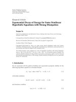
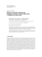
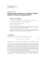
Figures 3(a), 3(b), 3(c), we plotted the probability of ATR er-
ror with different delay-Doppler uncertainty. Observe these
figures.
(1) The two RSNs tremendously reduce the ATR er-
ror comparing to a single-radar system in ATR with delay-
Doppler uncertainty, for example, the 10-radar RSN can
achieve ATR er ror 9% comparing against the single-radar
system with ATR error 22% at SNR
= 22 dB with
delay-Doppler uncertainty τ
∈ [−0.2T,0.2T]andF
D
i
∈
[−500 Hz, 500Hz].
(2) Comparing Figures 2(a), 2(b), 2(c) against Figures
3(a), 3(b), 3(c), the gain of 10-radar RSN for fluctuating tar-
get recognition is much larger than that for nonfluctuating
Qilian Liang 7
32313029282726
Average SNR (dB)
10
2
10
1
10
0
Probability of ATR error
Single radar
5radars
10 radars
(a)
32313029282726
Average SNR (dB)
10
2
10
1
10
0
Probability of ATR error
Single radar
5radars
10 radars
(b)
32313029282726
Average SNR (dB)
10
2
10
1
10
0
Probability of ATR error
Single radar
5radars
10 radars
(c)
Figure 2: The average probability of ATR error for 6 fluctuating targets with different delay-Doppler uncertainty: (a) no delay-Doppler
uncertainty, (b) with delay-Doppler uncertainty, τ
∈ [−0.1T,0.1T]andF
D
i
∈ [−200 Hz, 200 Hz], and (c) with delay-Doppler uncertainty,
τ
∈ [−0.2T,0.2T]andF
D
i
∈ [−500 Hz, 500 Hz].
target recognition, which means our RSN has better c apacity
to handle the fluctuating targets. In real world, fluctuating
targets are more meaningful a nd realistic.
(3) Comparing Figures 3(a), 3(b), 3(c) against Figures
2(a), 2(b), 2(c),theATRneedsmuchlowerSNRfornonfluc-
tuating target recognition because Rician distribution has di-
rect path component.
6. CONCLUSIONS AND FUTURE WORKS
We have studied LFM waveform design and diversity in
radar sensor networks (RSN). We showed that the LFM
waveforms can coexist if the carrier frequency spacing is
1/T between two radar waveforms. We made analysis on
interferences among waveforms in RSN and proposed a
RAKE structure for waveform diversity combining in RSN.
We applied the RSN to automatic target recognition (ATR)
with delay-Doppler uncertainty and proposed maximum-
likehood (ML)-ATR algorithms for fluctuating targets and
nonfluctuating targets. Simulation results show that RSN us-
ing our waveform diversity-based ML-ATR algorithm per-
forms much better than single-radar system for fluctuat-
ing targets and nonfluctuating targets recognition. It is also
demonstrated that our LFM waveform-based RSN can han-
dle the delay-Doppler uncertaint y which quite often happens
for ATR in target search phase.
The waveform design and diversity algorithms proposed
in this paper can also be applied to active RFID sensor
networks and underwater acoustic sensor networks because
LFM waveforms can also be used by these active sensor
8 EURASIP Journal on Wireless Communications and Networking
22212019181716
Average SNR (dB)
10
2
10
1
10
0
Probability of ATR error
Single radar
5radars
10 radars
(a)
22212019181716
Average SNR (dB)
10
2
10
1
10
0
Probability of ATR error
Single radar
5radars
10 radars
(b)
22212019181716
Average SNR (dB)
10
2
10
1
10
0
Probability of ATR error
Single radar
5radars
10 radars
(c)
Figure 3: The average probability of ATR error for 6 nonfluctuating targets with different delay-Doppler uncertainty: (a) no delay-Doppler
uncertainty, (b) with delay-Doppler uncertainty, τ
∈ [−0.1T,0.1T]andF
D
i
∈ [−200 Hz, 200 Hz], and (c) with delay-Doppler uncertainty,
τ
∈ [−0.2T,0.2T]andF
D
i
∈ [−500 Hz, 500 Hz].
networks to perform collaborative monitoring tasks. In this
paper, the ATR is for single-target recognition. We will con-
tinuously investigate the ATR when multiple targets coexist
in RSN and each target has delay-Doppler uncertainty. In our
waveform diversity combining, we have used spatial diversity
combining in this paper. We will further investigate spatial-
temporal-frequency combining for RSN waveform diversity.
ACKNOWLEDGMENTS
This work was supported by the US Office of Naval Research
(ONR) Young Investigator Program Award under Grant no.
N00014-03-1-0466. The author would like to thank ONR
Program Officer Dr. Rabinder N. Madan for his direction and
insightful discussion on radar sensor networks.
REFERENCES
[1] R. A. Johnson and E. L. Titlebaum, “Range-doppler uncou-
pling in the doppler tolerant bat signal,” in Proceedings of IEEE
Ultrasonics Symposium, pp. 64–67, Boston, Mass, USA, Octo-
ber 1972.
[2] S.M.SowelamandA.H.Tewfik,“Waveformselectioninradar
target classification,” IEEE Transactions on Information Theory,
vol. 46, no. 3, pp. 1014–1029, 2000.
[3] P. M. Baggenstoss, “Adaptive pulselength correction (APLE-
CORR): a strategy for waveform optimization in ultraw-
ideband active sonar,” IEEE Journal of Oceanic Engineering,
vol. 23, no. 1, pp. 1–11, 1998.
[4] D.J.KershawandR.J.Evans,“Optimalwaveformselectionfor
tracking systems,” IEEE Transactions on Information Theory,
vol. 40, no. 5, pp. 1536–1550, 1994.
Qilian Liang 9
[5] R. Niu, P. Willett, and Y. Bar-Shalom, “Tracking considera-
tions in selection of radar waveform for range and range-rate
measurements,” IEEE Transactions on Aerospace and Electronic
Systems, vol. 38, no. 2, pp. 467–487, 2002.
[6] Y. Sun, P. Willett, and R. Lynch, “Waveform fusion in sonar
signal processing,” IEEE Transactions on Aerospace and Elec-
tronic Systems, vol. 40, no. 2, pp. 462–477, 2004.
[7] M. I. Skolnik, Introduction to Radar Systems,McGrawHill,
New York, NY, USA, 3rd edition, 2001.
[8] H. Deng, “Synthesis of binary sequences with good auto-
correlation and cross-correlation properties by simulated an-
nealing,” IEEE Transactions on Aerospace and Electronic Sys-
tems, vol. 32, no. 1, pp. 98–107, 1996.
[9] Q. Liang, “Waveform design and diversity in radar sensor net-
works: theoretical analysis and application to automatic tar-
get recognition,” in Proceedings of International Workshop on
Wireless Ad Hoc and Sensor Networks (IWWAN ’06),NewYork,
NY, USA, June 2006.
[10] M. A. Richards, Fundamentals of Radar Signal Processing,
McGraw-Hill, New York, NY, USA, 2005.
[11] C. R. Lin and M. Gerla, “Adaptive clustering for mobile wire-
less networks,” IEEE Journal on Selected Areas in Communica-
tions, vol. 15, no. 7, pp. 1265–1275, 1997.
[12] A. Iwata, C C. Chiang, G. Pei, M. Gerla, and T W. Chen,
“Scalable routing strategies for ad hoc wireless networks,”
IEEE Journal on Selected Areas in Communications, vol. 17,
no. 8, pp. 1369–1379, 1999.
[13] T C. Hou and T J. Tsai, “An access-based clustering protocol
for multihop wireless ad hoc networks,” IEEE Journal on Se-
lected Areas in Communications, vol. 19, no. 7, pp. 1201–1210,
2001.
[14] M. Steenstrup, “Cluster-based networks,” in Ad Hoc Network-
ing, C. Perkins, Ed., chapter 4, pp. 75–138, Addison-Wesley,
Reading, Mass, USA, 2001.
[15] P. Swerling, “Probability of detection for fluctuating targets,”
IEEE Transactions on Information Theory,vol.6,no.2,pp.
269–308, 1960.